Vehicle will not start

Tiny
DWAIN JONES
  • MEMBER
  • 2003 FORD ESCAPE
  • 3.0L
  • V6
  • 4WD
  • AUTOMATIC
  • 180,000 MILES
After replacing the head gaskets I put everything back as it was. Same cam caps, lifters and rollers all in the same place they came out of, with the exception of four new lifters. My problem is after I got everything back together (by the Haynes manual) it wouldn't start. I took the timing chain cover back off and checked as by the Haynes manual. I believe their diagram of the cams not accurate. Other diagrams show the cam marks in a different location. The Haynes manual puts the valves in a neutral position. The other diagram puts the cams on the right head pushing some valves in. So, heads on, cams in, chains off. How do I set the timing from here?
Monday, May 6th, 2019 AT 6:08 PM

46 Replies

Tiny
JACOBANDNICKOLAS
  • MECHANIC
  • 108,170 POSTS
Welcome to 2carpros. Com

Here are the directions from Alldata for removal and replacement. The attached pictures correlate with these directions.

_________________________________________________

TIMING DRIVE COMPONENTS
Timing Drive Components

Removal

NOTICE: During engine repair procedures, cleanliness is extremely important. Any foreign material, including any material created while cleaning gasket surfaces that
enters the oil passages, coolant passages or the oil pan, can cause engine failure.

NOTICE: Failure to verify correct timing drive component alignment will result in severe engine damage.

1. Remove the engine front cover.

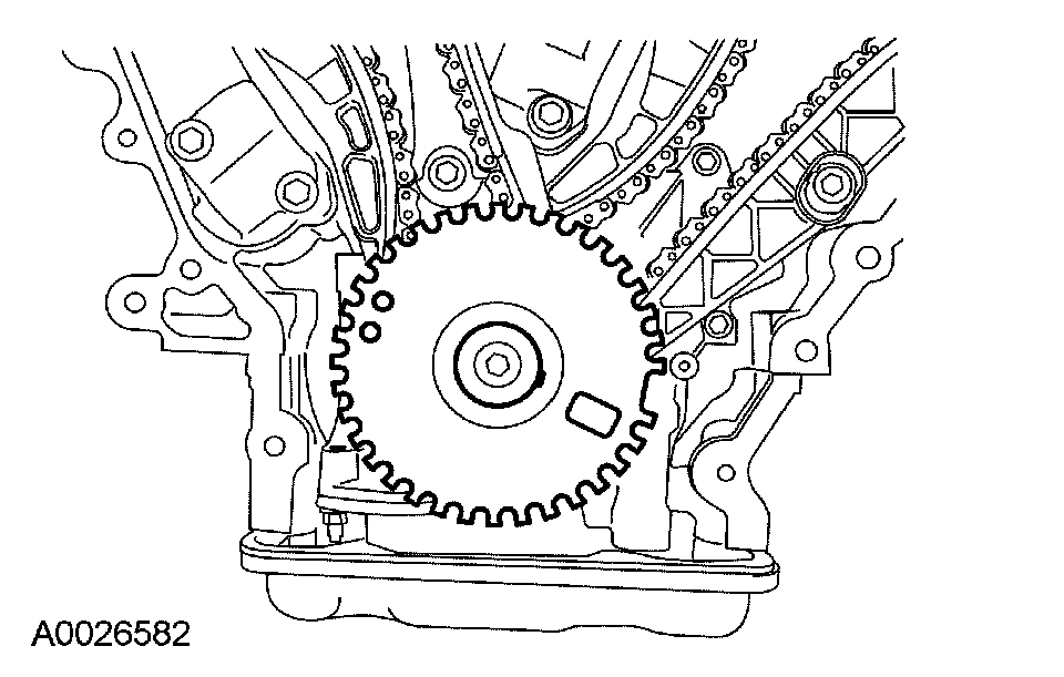
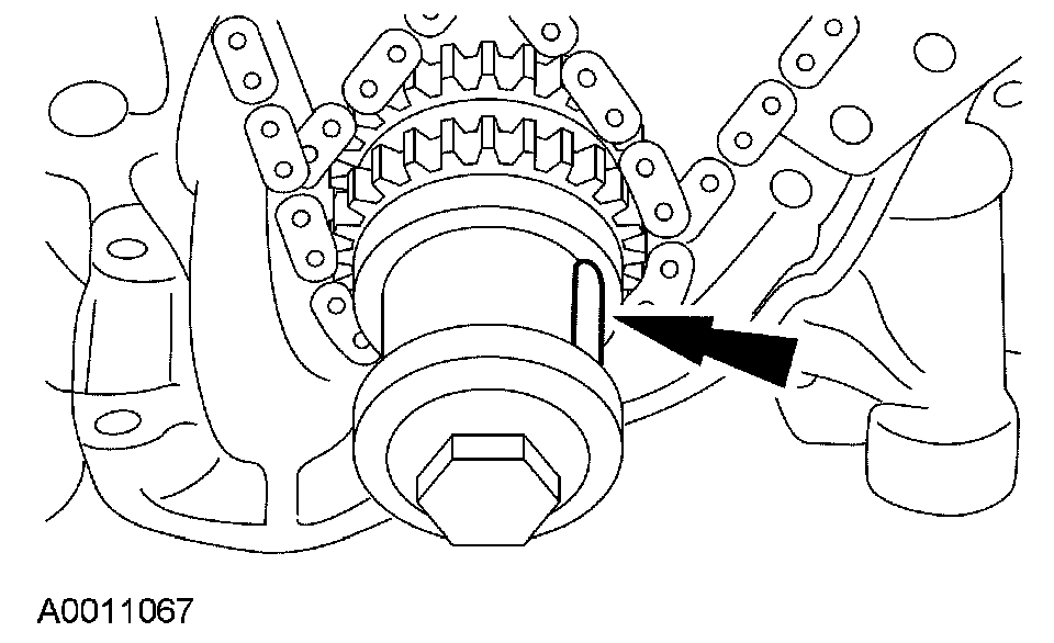
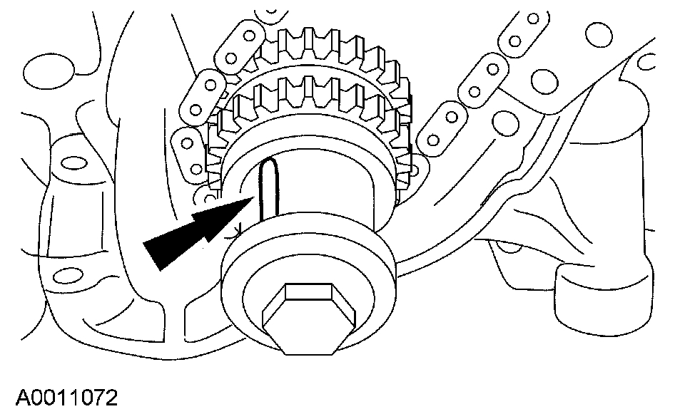
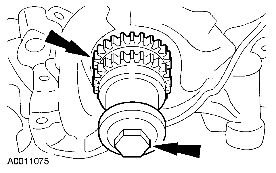
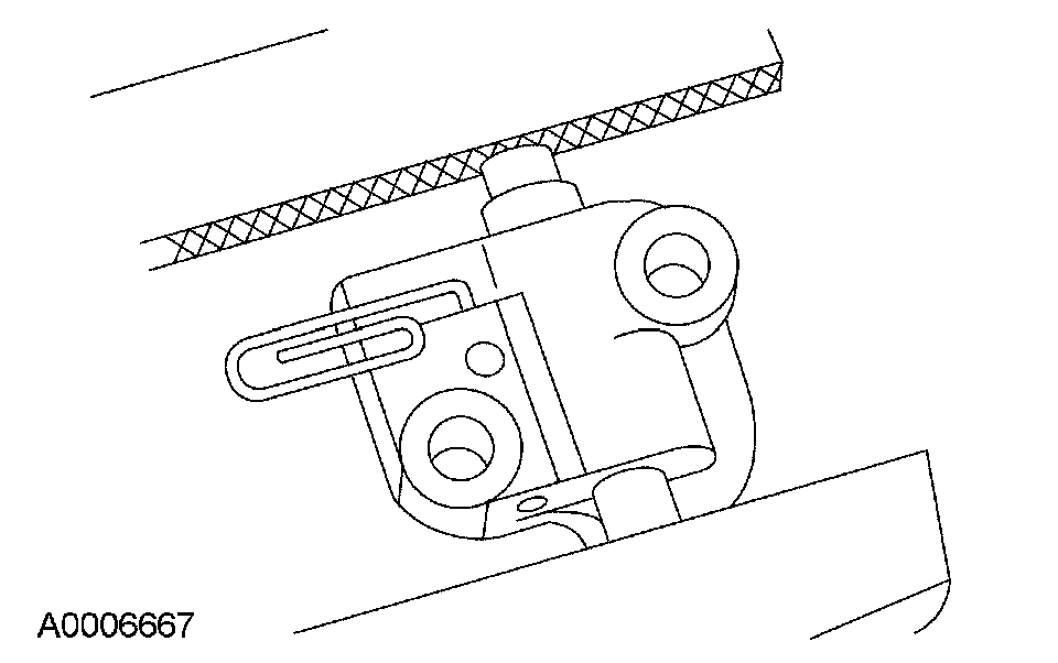
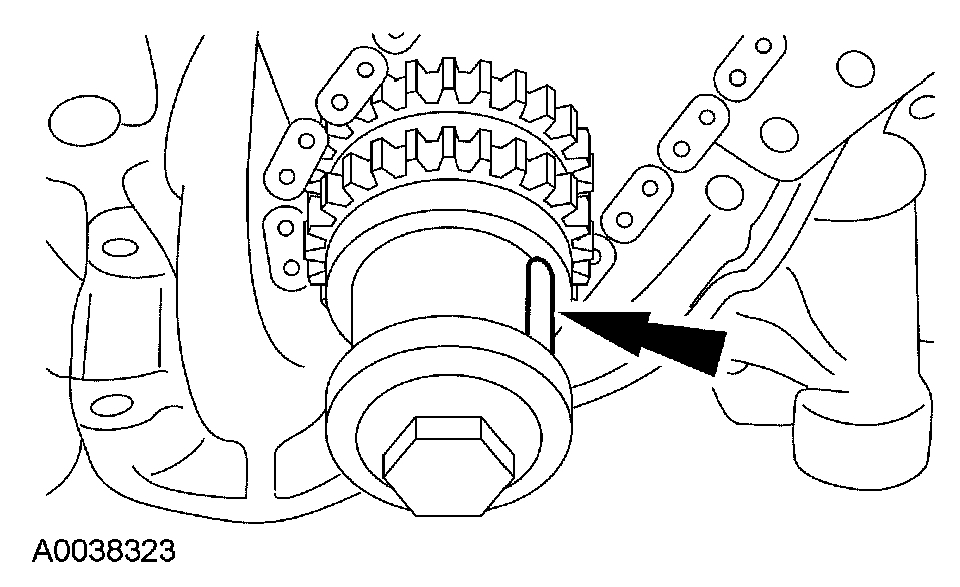
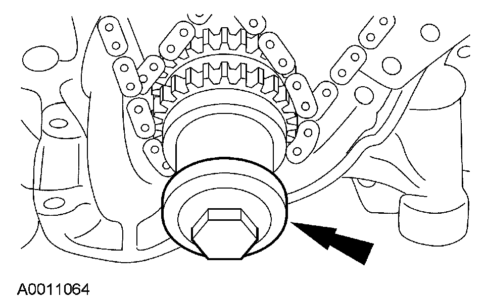
2. NOTICE: This pulse wheel is used in several different engines. Install the pulse wheel with the keyway in the slot stamped "25-25-34Y-30M"(color blue).

Pic 1

Remove the ignition pulse wheel.
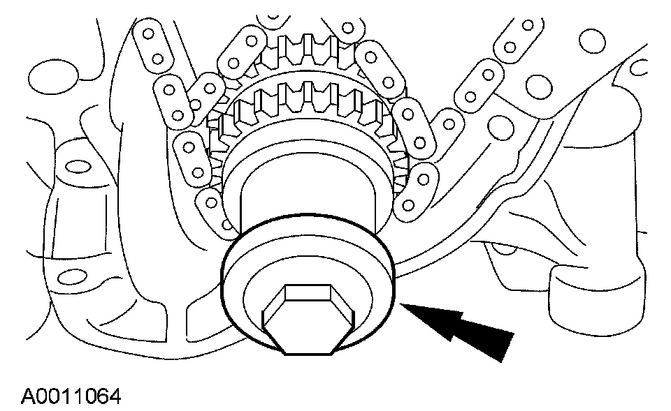
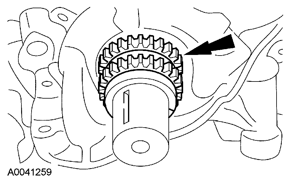
Pic 2

3. Install the damper bolt.

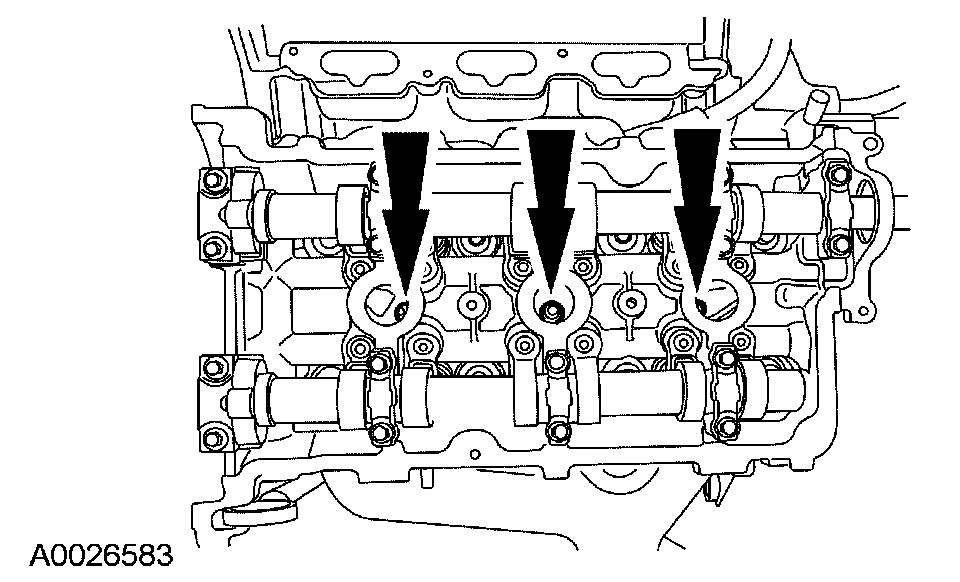
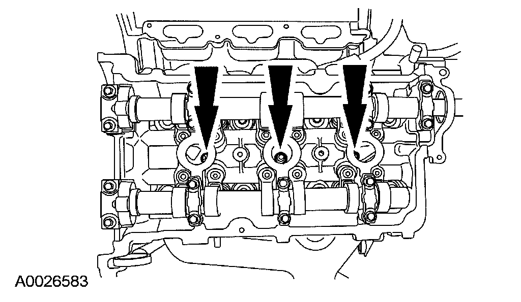
4. NOTE: LH shown, RH similar.

Pic 3

Remove the LH and RH spark plugs.

Pic 4

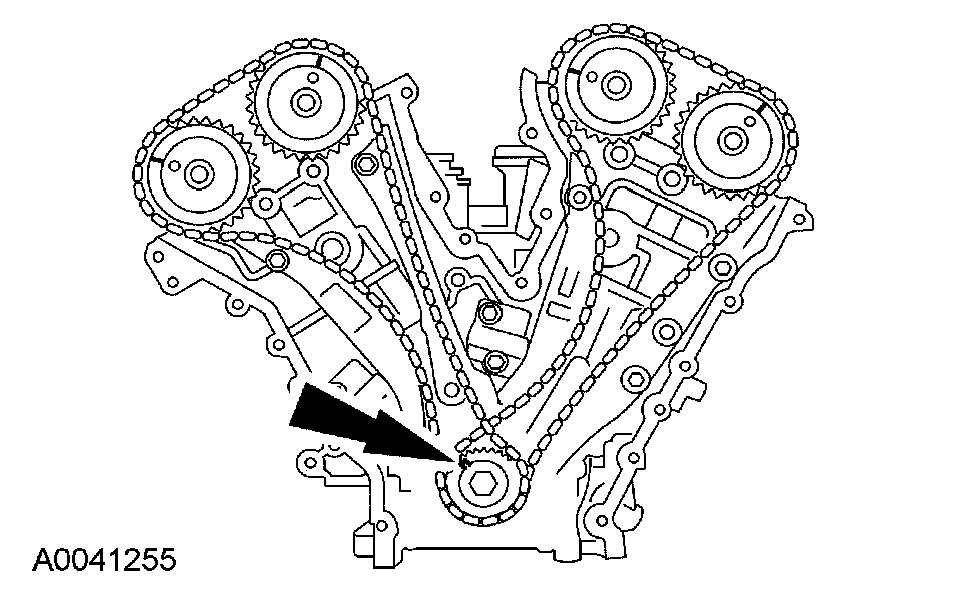
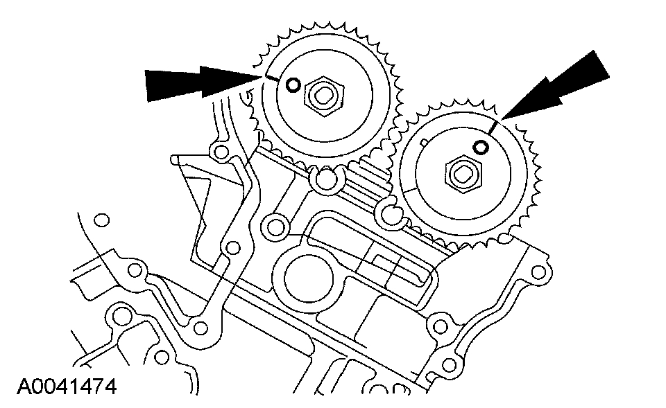
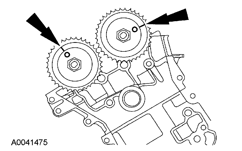
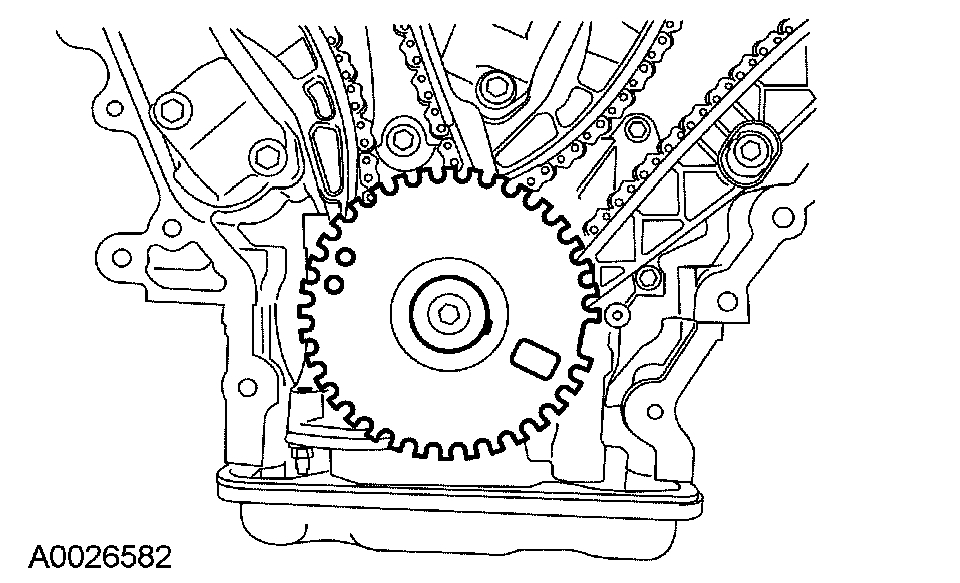
5. Rotate the crankshaft clockwise to position the crankshaft keyway in the 11 o'clock position and position the camshafts in the correct position. This will position the number one cylinder at top dead center (TDC).
- Verify that the camshafts are correctly located. If not, rotate the crankshaft one additional turn and recheck.

Pic 5

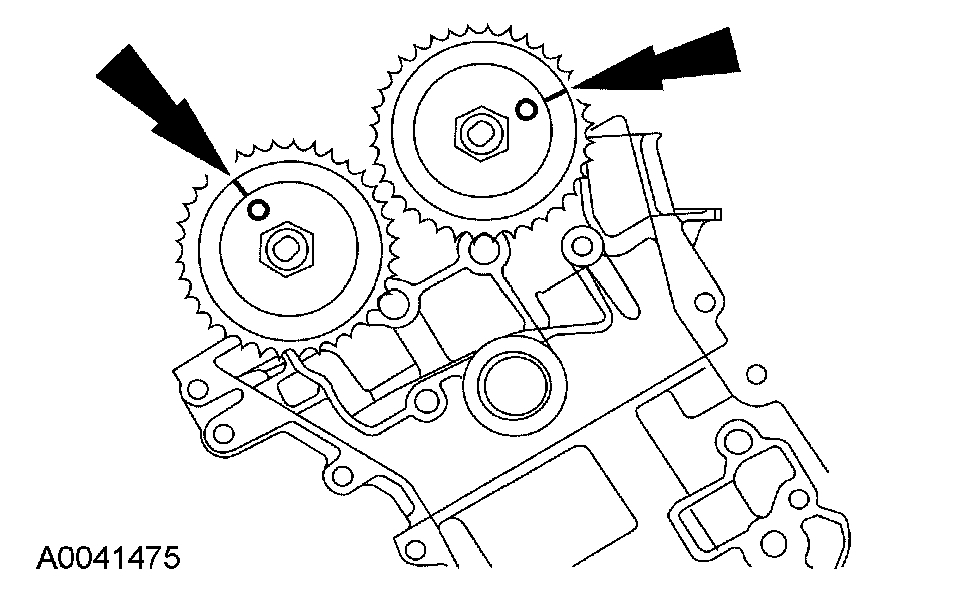
6. Rotate the crankshaft clockwise 120 degrees to the 3 o'clock position to locate the RH camshafts in the neutral position.

Pic 6

7. Verify that the RH camshafts are in the neutral position.

Pic 7

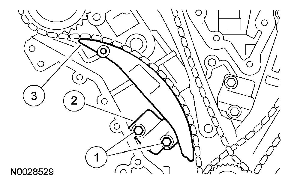
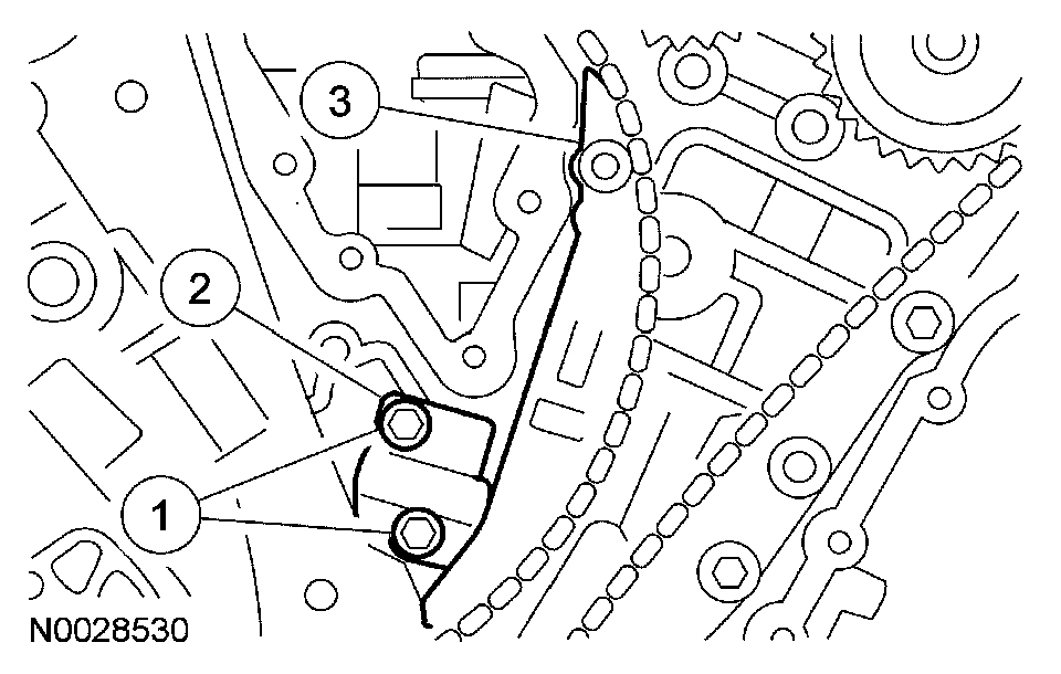
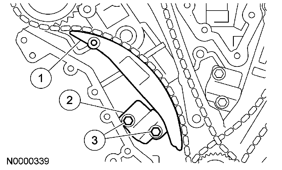
8. Remove the RH timing chain tensioner arm.
1. Remove the bolts.
2. Remove the tensioner.
3. Remove the tensioner arm.

Pic 8

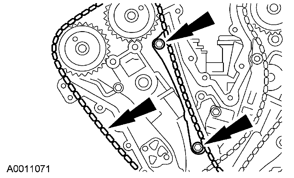
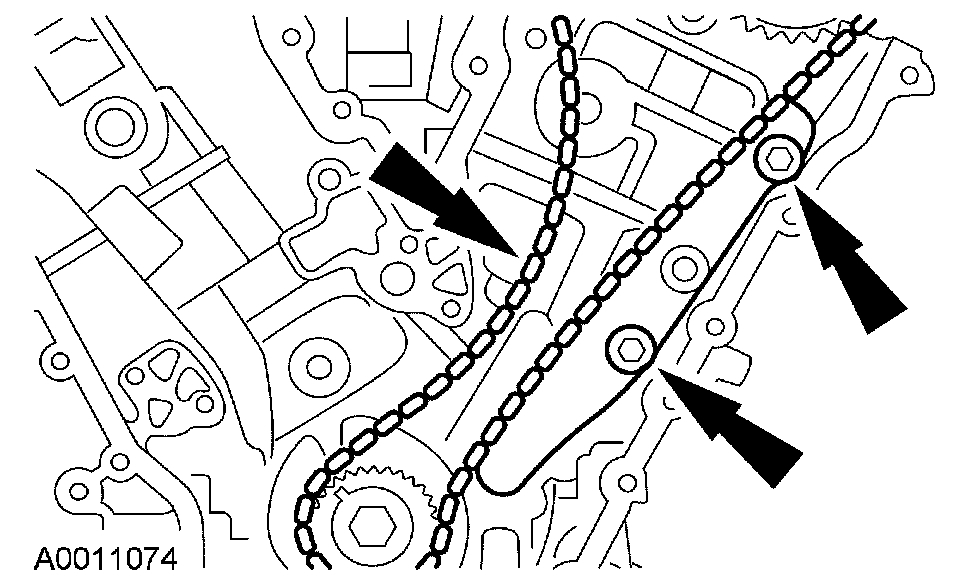
9. Remove the bolts, RH timing chain guide and the timing chain.

Pic 9

10. Rotate the crankcase clockwise 600 degrees (1-2/3 turns) to position the crankcase keyway in the 11 o'clock position. This will position the LH camshafts in the neutral position.

Pic 10

11. Verify the LH camshafts are in the neutral position.

Pic 11

12. Remove the LH timing chain and tensioner arm.
1. Remove the bolts.
2. Remove the tensioner.
3. Remove the tensioner arm.

Pic 12

13. Remove the LH timing chain and timing chain guide.

Pic 13

14. Remove the damper bolt and the crankshaft sprockets.

Installation

1. NOTICE: Failure to verify correct timing drive component alignment will result in severe engine damage.

Pic 14

Install the crankshaft sprocket with the timing mark facing out.

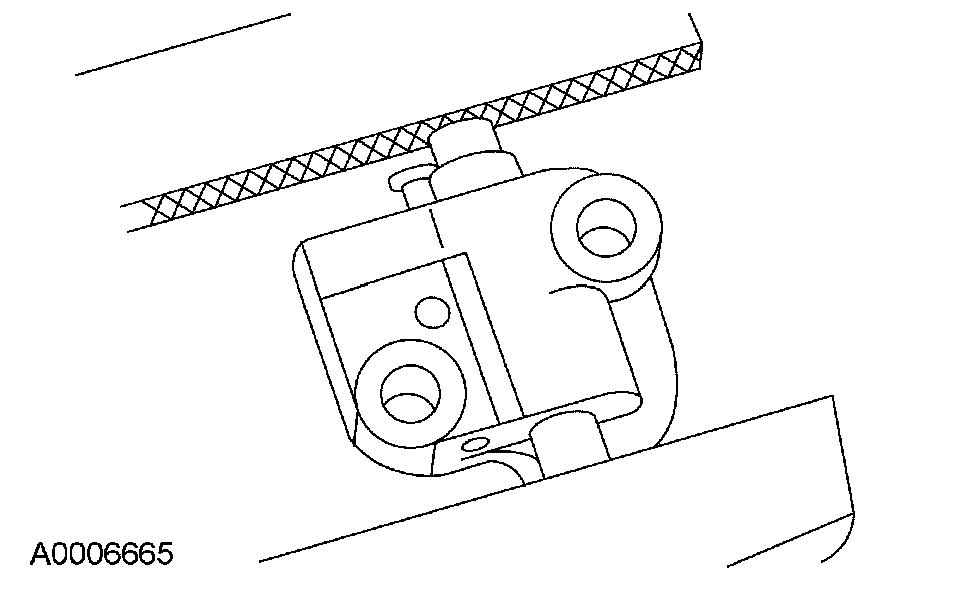
2. NOTE: LH shown, RH similar.

Pic 15

Position the chain tensioner in a soft-jawed vise.

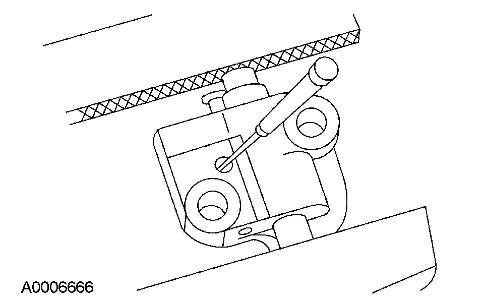
3. NOTE: LH shown, RH similar.

Pic 16

Hold the chain tensioner ratchet lock mechanism away from the ratchet stem with a small pick.

4. NOTICE: During tensioner compression, do not release the ratchet stem until the tensioner piston is fully bottomed in its bore or damage to the ratchet stem will result.

Pic 17

Slowly compress the timing chain tensioner.

5. Retain the tensioner piston with a 1.5 mm (0.05 in) wire or paper clip.

Pic 18

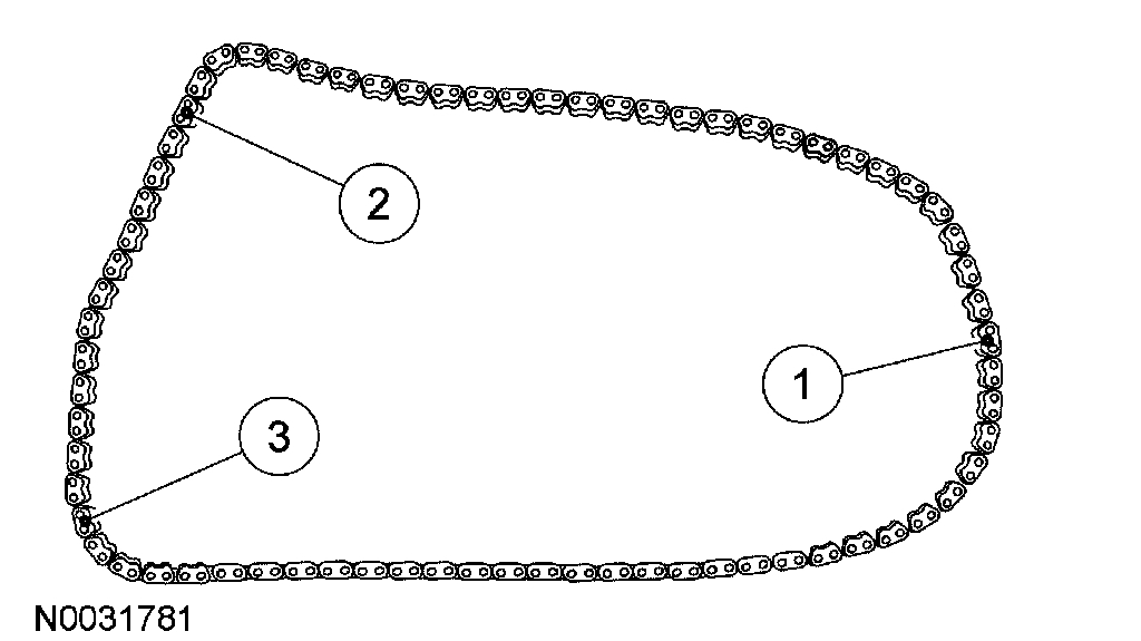
6. If timing marks in the timing chains are not evident, use a permanent-type marker to mark the crankshaft and camshaft timing marks on the LH and RH timing chains.
1. Mark any link to use as the crankshaft timing mark.
2. Starting with the crankshaft timing mark, count 29 links and mark the link.
3. Continue counting to link 42 and mark the link.

Pic 19

7. Position the LH timing chain and guide and install the bolts.
- Align the marks on the timing chain with the marks on the camshaft and crankshaft sprockets.
- Tighten to 25 Nm (18 lb-ft).

Pic 20

8. Install the LH timing chain tensioner arm and the LH timing chain tensioner.
1. Install the tensioner arm.
2. Position the tensioner.
3. Install the bolts.
-Tighten to 25 Nm (18 lb-ft).

Pic 21

9. Install the crankshaft damper bolt and rotate the crankshaft clockwise 120 degrees until the crankshaft keyway is in the 3 o'clock position.

Pic 22

10. Verify that the RH camshafts are correctly positioned.

Pic 23

11. Install the RH timing chain and chain guide and install the bolts.
- Align the marks on the timing chain with the marks on the camshaft and crankshaft sprokets.
- Tighten to 25 Nm (18 lb-ft).

Pic 24

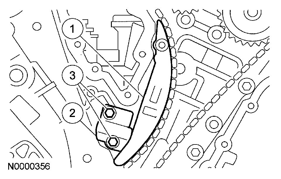
12. Install the RH timing chain tensioner and tensioner arm.
1. Install the tensioner arm.
2. Position the tensioner.
3. Install the bolts.
- Tighten to 25 Nm (18 lb-ft).
13. Remove the LH and RH timing chain tensioner piston retaining wires.
14. Rotate the crankshaft counterclockwise 120 degrees to top dead center (TDC).

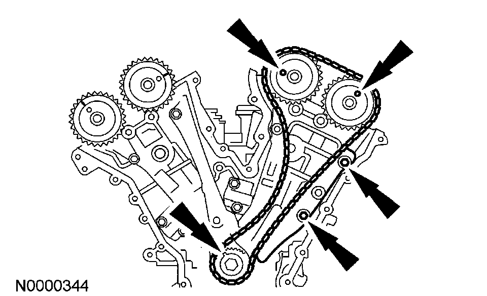
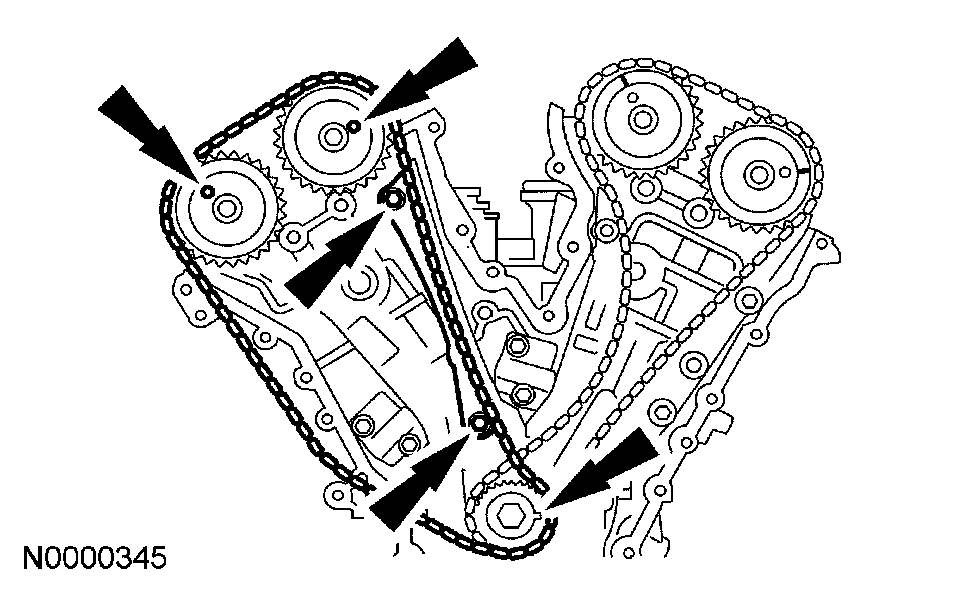
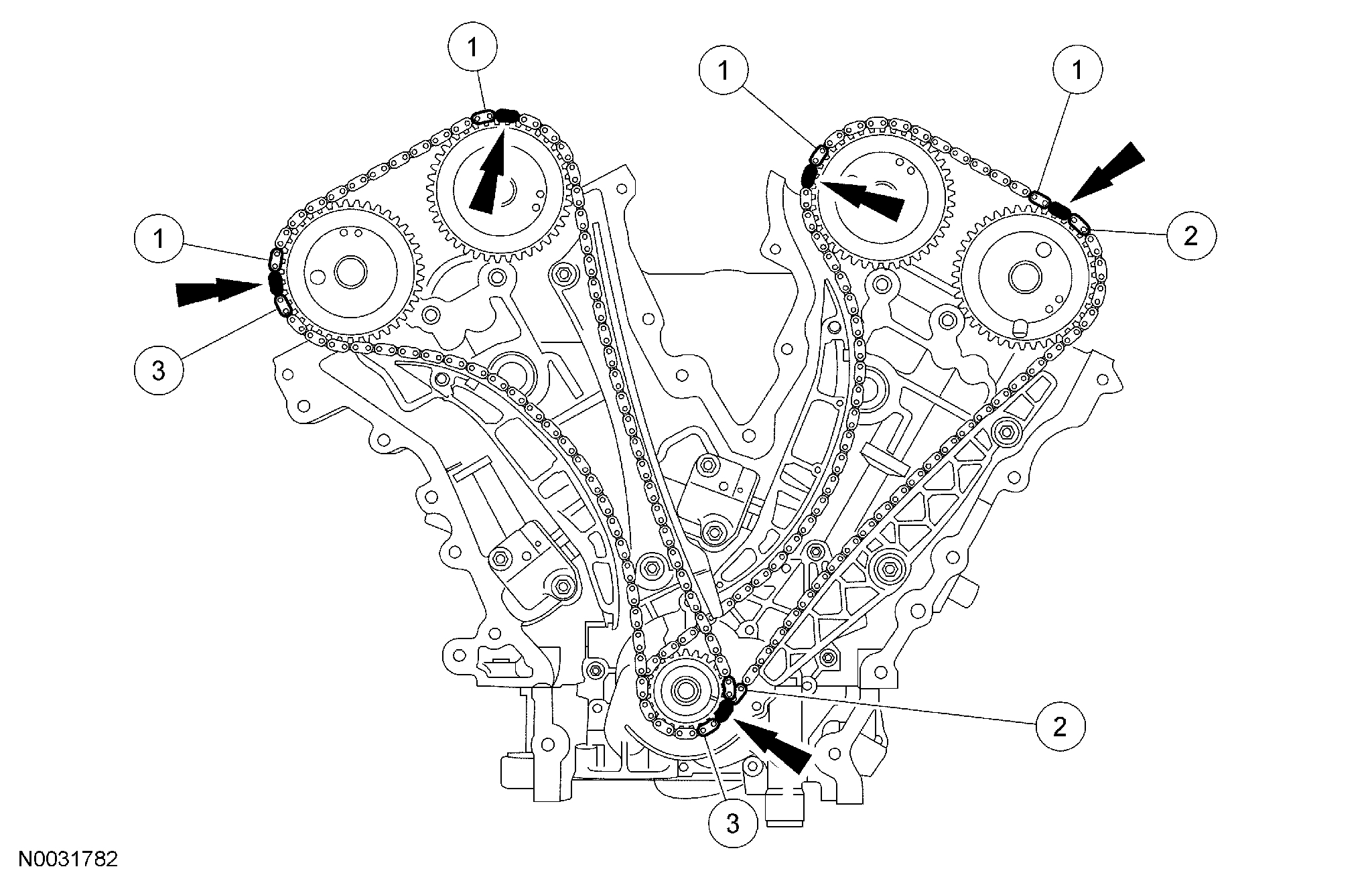
15. NOTICE: Failure to verify correct timing drive component alignment will result in severe engine damage.

Pic 25

Verify the timing with the following steps.
1. There should be 12 chain links between the camshaft timing marks.
2. There should be 27 chain links between the camshaft and the crankshaft timing marks.
3. There should be 30 chain links between the camshaft and the crankshaft timing marks.

Pic 26

16. Remove the crankshaft damper bolt.

17. NOTE: LH shown, RH similar

pic 27

Install the LH and RH spark plugs.
-Tighten to 15 Nm (11 lb-ft).

18. NOTICE: This pulse wheel is used in several different engines. Install the pulse wheel with the keyway in the slot stamped '20-25-34Y-30M" (color blue).

Pic 28

-Install the ignition pulse wheel.

19. Install the engine front cover.

_______________________________________________________

Let me know if this helps.

Take care,
Joe
Was this
answer
helpful?
Yes
No
+1
Wednesday, August 12th, 2020 AT 1:34 PM
Tiny
DWAIN JONES
  • MEMBER
  • 27 POSTS
Thanks. I will follow this through.
Was this
answer
helpful?
Yes
No
+1
Wednesday, August 12th, 2020 AT 1:34 PM
Tiny
KEN L
  • MASTER CERTIFIED MECHANIC
  • 42,878 POSTS
Please do JACOBANDNICKOLAS is one of our best! Use 2CarPros anytime, we are here to help. Please tell a friend.
Was this
answer
helpful?
Yes
No
Wednesday, August 12th, 2020 AT 1:34 PM
Tiny
DWAIN JONES
  • MEMBER
  • 27 POSTS
Did everything according to the Alldata directions. Problem, the engine wan't start. Sounds better than before. Cranks over good, but wan't start. First I didn't have spark or fuel. After I put the crankshaft pulley back on I got spark, (I don't know how that effected things). Before I started this project everything run well, just used too much water (with condensation coming out the exhaust). I've had this thing (the timing chain cover) apart three times now and I don't understand why it doesn't work. Each time I put the timing chains back on according to all the instructions I've received, everything looks just like the diagrams you sent. All the electrical connections are right. And I can't find any loose ends or anything disconnected. What I wouldn't give for a distributor, then I could tell where number one is or how far off I am.
Was this
answer
helpful?
Yes
No
Wednesday, August 12th, 2020 AT 1:34 PM
Tiny
JACOBANDNICKOLAS
  • MECHANIC
  • 108,170 POSTS
Welcome back:

Okay, I need you to check one more thing, engine compression. By doing that, I will know if something isn't together correctly, specifically timing. They are not easy to time. My biggest concern is if you had it together wrong and tried starting it. Ford's 3.0L engine is an interference engine. If not timed correctly, internal damage can occur when cranking.

Do this compression test and let me know the results.

https://www.2carpros.com/articles/how-to-test-engine-compression

Here are the directions specific to your vehicle. The two attached pictures are related to compression readings. If you have questions related to them, let me know.

__________________________________

AllData Editors Note - Ford does not provide a cranking pressure specification, only an acceptable range.

Compression Test Compression Gauge Check
1. Make sure the oil in the crankcase is of the correct viscosity and at the correct level and that the battery is correctly charged. Operate the vehicle until the engine is at normal operating temperature. Turn the ignition switch to the OFF position, then remove all the spark plugs.
2. Set the throttle plates in the wide-open position.
3. Install a compression gauge such as the Compression Tester in the No. 1 cylinder.
4. Install an auxiliary starter switch in the starting circuit. With the ignition switch in the 0FF position, and using the auxiliary starter switch, crank the engine a minimum of five compression strokes and record the highest reading. Note the approximate number of compression strokes required to obtain the highest reading.
5. Repeat the test on each cylinder, cranking the engine approximately the same number of compression strokes.

Compression Test-Test Results
The indicated compression pressures are considered within specification if the lowest reading cylinder is at least 75 percent of the highest reading. Refer to the Compression Pressure Limit Chart.

picture 1

picture 2

Compression Pressure Limit Chart

If one or more cylinders reads low, squirt approximately one tablespoon of engine oil on top of the pistons in the low-reading cylinders. Repeat the compression pressure check on these cylinders.

Compression Test Interpreting Compression Readings
1. If compression improves considerably, piston rings are faulty.
2. If compression does not improve, valves are sticking or seating incorrectly.
3. If two adjacent cylinders indicate low compression pressures and squirting oil on each piston does not increase compression, the head gasket may be leaking between cylinders. Engine oil or coolant in cylinders could result from this condition.

Use the Compression Pressure Limit Chart when checking cylinder compression so that the lowest reading is at least 75 percent of the highest reading.

___________________________________________-

Let me know the results.

Joe
Was this
answer
helpful?
Yes
No
Wednesday, August 12th, 2020 AT 1:34 PM
Tiny
DWAIN JONES
  • MEMBER
  • 27 POSTS
Okay. I want you to know that before I started this whole project I did a compression check to see if I could find any cylinder that may be the cause of my water leak. The compression at that time was #1 188, #2 208 #3 195 #4 210 #5 198 and #6 212. After the first try at setting the timing right and failing, I did a compression test and was blown away by how much lower the compression was. This third time they are about the same as the last time. They are, #1 162. #2 168. #3 163. #4 160. #5 140. #6 142. I added oil to the last two cylinders and ran the test again but no change. How is it that the engine doesn't even try to start? I mean, no sign of it wanting to fire up. Thanks.
Was this
answer
helpful?
Yes
No
Wednesday, August 12th, 2020 AT 1:34 PM
Tiny
DWAIN JONES
  • MEMBER
  • 27 POSTS
Did you get the note I sent today about 12:30?
Was this
answer
helpful?
Yes
No
Wednesday, August 12th, 2020 AT 1:34 PM
Tiny
JACOBANDNICKOLAS
  • MECHANIC
  • 108,170 POSTS
Welcome back:

I agree, it should be at least trying to start. Are you sure you are getting spark and fuel to the engine? See if it starts for a couple seconds with starting fluid. If it does, then it is a fuel related issue. If it doesn't or at least try, you need to confirm you are getting a good hot spark to the plugs.

https://www.2carpros.com/articles/how-to-check-fuel-system-pressure-and-regulator

https://www.2carpros.com/articles/how-to-test-an-ignition-system

Let me know if you have already done this or similar tests and their results.

Thanks,
Joe
Was this
answer
helpful?
Yes
No
Wednesday, August 12th, 2020 AT 1:34 PM
Tiny
DWAIN JONES
  • MEMBER
  • 27 POSTS
What I found is I'm not getting proper voltage to the coils. I checked #'s 4, 5, and 6. While cranking, each coil connector produced only 1.5 to 3.0 volts. Very low voltage, right? I had my volt meter set to 20 volt D.C. Setting. I hope my meter isn't bad also. Is it common to have to plug in a code reader after changing anything? Will that help? Could the crankcase position sensor have something to do with my problem? I haven't checked the fuel pressure yet. I wanted to correct the voltage problem first.
Was this
answer
helpful?
Yes
No
Wednesday, August 12th, 2020 AT 1:34 PM
Tiny
JACOBANDNICKOLAS
  • MECHANIC
  • 108,170 POSTS
Welcome back:
That is too low. Retrace your original steps to confirm there are no wires pinched or damaged where you worked. Take a look at the attached picture. Note that all coils are spliced together (white/violet). I highlighted the wires I'm referring to, so they appear yellow. Note the location of these splices as indicated and confirm condition.

Make sure nothing is loose, damaged, pinched and so on.

Let me know the results.

Joe
Was this
answer
helpful?
Yes
No
Wednesday, August 12th, 2020 AT 1:34 PM
Tiny
DWAIN JONES
  • MEMBER
  • 27 POSTS
I checked the wiring from the coil connectors to the PCM. Have continuity all the way. No wires grounded. Checked again for voltage on coil and on injectors, injectors 12+ volts, coils, zip. Would a code reading help? Is there any way to reset the PCM?
Was this
answer
helpful?
Yes
No
Wednesday, August 12th, 2020 AT 1:34 PM
Tiny
JACOBANDNICKOLAS
  • MECHANIC
  • 108,170 POSTS
Welcome back:

No reset on the PCM. However, have you checked at the PCM for power to the coils? You could have a wiring issue between the two.

Let me know.

Joe
Was this
answer
helpful?
Yes
No
Wednesday, August 12th, 2020 AT 1:34 PM
Tiny
DWAIN JONES
  • MEMBER
  • 27 POSTS
Sorry, Joe. I don't understand your message. I HAVE (not yelling, just can't find the underline key) continuity from the coil all the way back to the PCM. Its like a wire straight from the coil to the PCM. If I have power at the PCM it should make it to the coil, right? So, If I don't get voltage to the coils then could I have a problem with the PCM? You say there is no reset?
Was this
answer
helpful?
Yes
No
Wednesday, August 12th, 2020 AT 1:34 PM
Tiny
JACOBANDNICKOLAS
  • MECHANIC
  • 108,170 POSTS
Welcome back:

No problem. If you have power at the PCM but not to the coil, there is a break in the wire. Check it for continuity. If there is no continuity, the wire is broken at some point and creating an open circuit. Thus, the power can't make it to the coil.

Please feel free to ask anything. If I can help, I will. No need for being sorry.

Joe
Was this
answer
helpful?
Yes
No
Wednesday, August 12th, 2020 AT 1:34 PM
Tiny
DWAIN JONES
  • MEMBER
  • 27 POSTS
Sorry, Joe. I do have continuity from the PCM to the coil. This is the third time I have stated this. Is there some sensor or something else I can check that is supposed to send signals to the PCM?
Was this
answer
helpful?
Yes
No
Wednesday, August 12th, 2020 AT 1:34 PM
Tiny
KEN L
  • MASTER CERTIFIED MECHANIC
  • 42,878 POSTS
Will it run on starting fluid? With the key on do you have 12 volts at the coils? I would check all system grounds here is a guide to help you test the wiring and the engine wiring diagrams so you can see how the system works.

https://www.2carpros.com/articles/how-to-check-wiring

Make sure the PCM and ignition relay is working as well. Check out the diagrams (Below). Please let us know what you find. We are interested to see what it is.
Was this
answer
helpful?
Yes
No
Wednesday, August 12th, 2020 AT 1:34 PM
Tiny
DWAIN JONES
  • MEMBER
  • 27 POSTS
Hi, Ken. You were thinking I must have had success with my problem. No, I still can't get the engine to start. I hired a mobile mechanic (who came down with the flu and set things back about a week) to check out the electrical and he said everything was OK. He did a few other test and he suspects the timing. He said the way it turned over was uneven and also the smell of gas at the rear exhaust were some of the reasons for suspecting the timing. For the fourth time I took the timing cover off to check the timing and found it to be on the money. I took some pictures with my cell phone but couldn't get my computer to accept them so I'll try again with another camera. The way the timing marks are laid out is just as pictured in pic numbers 4 and 25 that you sent me. Everything looks good. I am puzzled by something though. When the marks are aligned as they are, when I turn the engine over by hand, with a breaker bar, the engine has to turn over a number of times before the marks align again. This made me think the timing chain had jumped the first time I set it. With the chain as long as it is I guess that is the reason. Also, when the # 1 cylinder is at TDC the cam looks like I would expect (ready for the power stroke) and with # 5 the cam is just the opposite. One other thing the mechanic said was the anti theft system was shut off and sometimes cars wan't start. He didn't mention if he reset it. Could something like that be my problem?
Was this
answer
helpful?
Yes
No
Wednesday, August 12th, 2020 AT 1:34 PM
Tiny
JACOBANDNICKOLAS
  • MECHANIC
  • 108,170 POSTS
Welcome back:

Is there any way you could record the sound of the engine when cranking and upload it for use to hear?

Let me know.

Joe
Was this
answer
helpful?
Yes
No
Wednesday, August 12th, 2020 AT 1:34 PM
Tiny
DWAIN JONES
  • MEMBER
  • 27 POSTS
At the moment I have the timing chain cover off again. I was waiting for the mechanic I hired to look at the timing, but I've lost all confidence in him after he tells me he would take time to look but he changed that to when he had time. He also told me there is a special tool to set the timing on this engine, plus, he told me over the phone the timing marks could not be on if I set it right. Back to your request. I think my camera could pick up the sound. Have a great weekend.
Was this
answer
helpful?
Yes
No
Wednesday, August 12th, 2020 AT 1:34 PM
Tiny
JACOBANDNICKOLAS
  • MECHANIC
  • 108,170 POSTS
Welcome back:
Since you have it apart again, follow the directions I listed above. There should be marks on the timing chains for each side. If there are no marks, follow the directions for counting the links in the chain. This is very important. I will also add that if it was put together wrong, it may have damaged internal parts (valves).

Joe
Was this
answer
helpful?
Yes
No
Wednesday, August 12th, 2020 AT 1:35 PM

Please login or register to post a reply.

Sponsored links