This guide will show you how to test the continuity of a wire in a particular circuit using a simple voltmeter which you can get from Amazon for about $30.00.
How Does it Work?
Wiring and wiring harnesses are run throughout the vehicle to give conductivity to various systems such as sensors, lights, door locks, window motors, computers (PCM and BCM) etc. These harnesses are usually bundled together with "break out" points where one or more wires are routed out of the harness to connect to the aforementioned motor, sensor or lighting system.
What Goes Wrong?
Electrical systems rely on good connections, over time vibrations and road conditions such as heat, rain, snow and the natural aging of wiring can cause these connections to become loose, broken, damaged or corroded. This can cause the system to malfunction and give codes for circuit high, low or open problems. Additionally, connection issues can cause non computer controlled systems to work intermittently or not at all.
Let's Jump In!
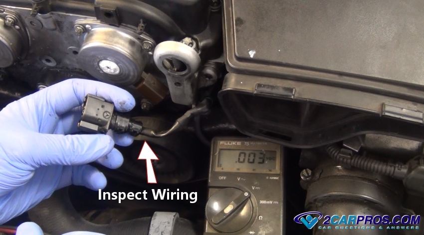
We are using a camshaft position sensor problem for this example, the sensor
has already been replaced but the "circuit open" code returns. Remember, this guide
can be applied to any part of the electrical system. The image below shows the sensor and connector with the
voltmeter ready for testing. Disconnect the connector from the sensor and check the wiring at the base of
the connector, this is a popular place for the wiring to break. Also, look for corrosion
or damaged pins as well.
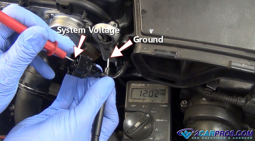
Most sensors or devices such as fuel injectors in a computer system are supplied
power from the computer called reference or supply voltage which is between 5 to
12 volts in most cases. Turn the key on and ready the voltmeter (how
to use a voltmeter). With the ignition key on, switch a voltmeter to DC voltage.
Then touch the negative lead to a good ground source. Use the positive lead to probe
the connector terminals, you should be able to find system voltage (This can also
help see if the computer system itself has power). If no voltage is observed you
may have a simple problem such as a
blown fuse. If voltage is present that part of the system is working.
For this step it helps to have a wiring diagram but it is not needed. All computer
wiring is identified by specific wiring color code such as, yellow and green yl/gn
which means yellow with a green stripe. The color mentioned first is the main color
of the wire followed by the tracer color which will be a small line on the wire.
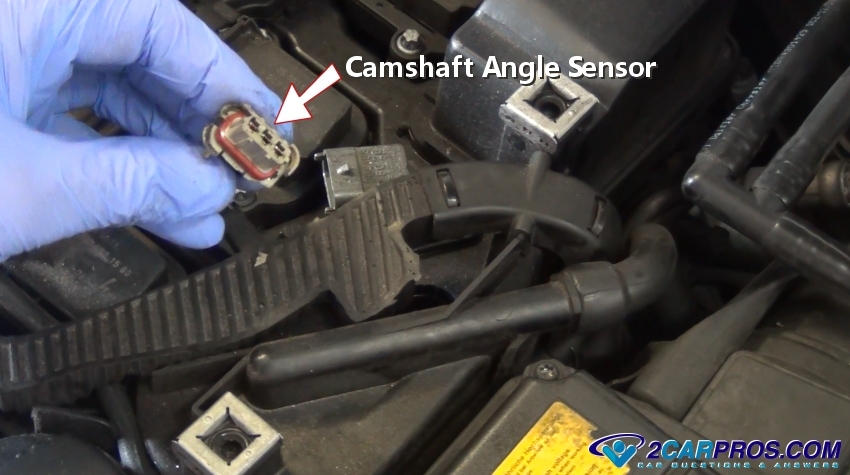
This color code will be the same from the sensor to the computer. In this example
we will use the camshaft angle/position sensor. This is a three wiring sensor, one
wire is used for sensor power, the other two go directly into the computer for sensing
purposes. Once system power is confirmed with the key on, the next step is to test
the connection between the sensor and the computer which will find broken wires.
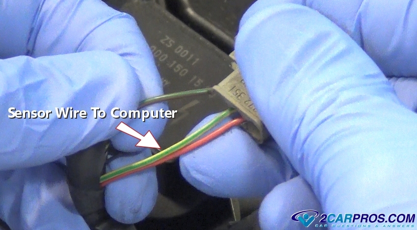
Identify the connector wiring colors, you may need to strip the wiring cover
back to see the individual colors. These are the wires you will be looking for at
the computer ECU (engine control unit).
Watch the Video!
This video is how to use an automotive test light which is good for checking for power and ground of any circuit (simple).
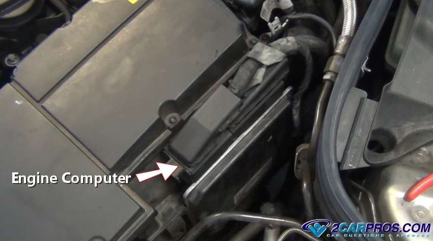
Locate the engine computer which is usually under the dash or in the engine compartment.
This one happens to be bolted to the air filter housing under the hood.
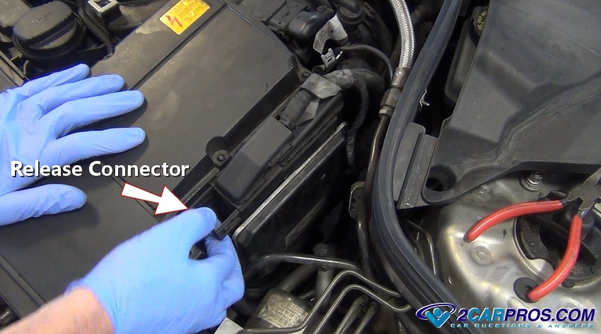
Locate and release the wiring connector to gain access to the electrical pins
which connect the system wiring into the computer.
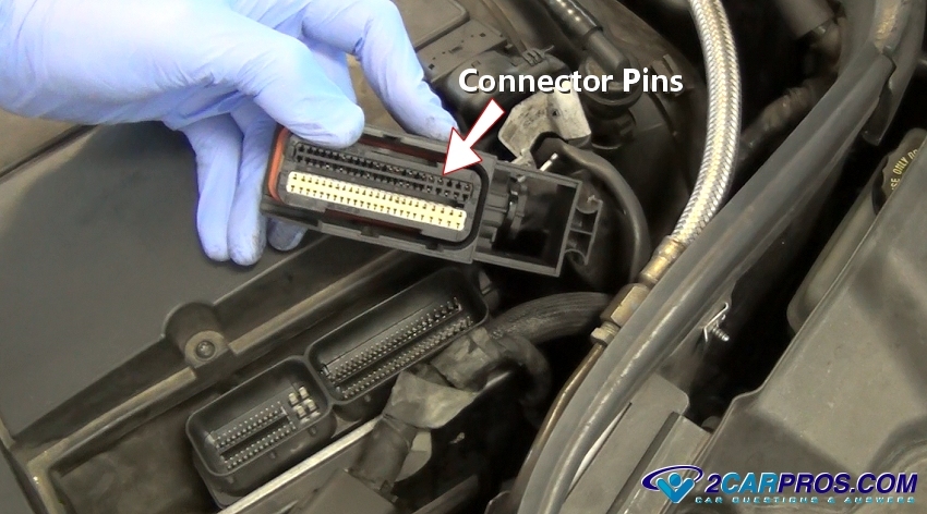
This will expose the connector pins which will be used for testing purposes.
While the connector is off check for the presence of engine oil which sounds kind
of weird but it has been known on high mileage engines that oil will seep from the
sensors, down the wiring and into the computer itself, like little rivers of oil.
If enough oil has been pushed into the computer it can short out the internal components,
even though oil doesn't conduct electricity it will saturate compounds which make
up the chips, resistors, capacitors and diodes causing them to fail. These connections
must be clean and free from dirt, oil, rust and corrosion.
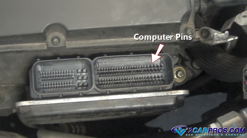
Computer's connect to the wiring harness using pins which attach to the various
components and to the motherboard inside the computer. Once the main connectors
have been removed check the pins for rust or corrosion and clean as necessary. It's
a good idea to spray electrical cleaner across the terminals and on the connectors.
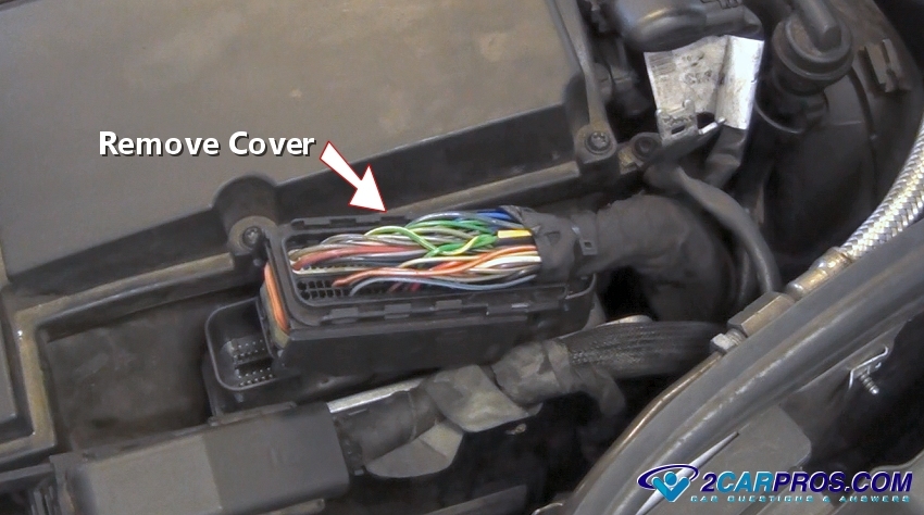
You must gain access to the wiring at the computer to identify the incoming wires.
In this case we have removed the plastic cover over the connector, in most cases
the wires are exposed naturally.
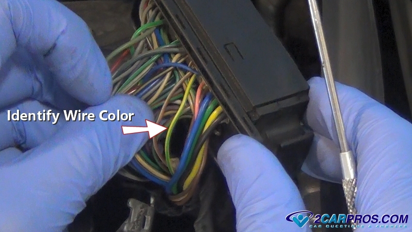
All wires should be clearly visible, look around until you find the same wire
color combination and size present at the sensor, (note: if two of the same color
wires are found, a wiring diagram to needed to identify the pin # to the particular
circuit being tested, this is rare). You can find wiring diagrams at
AllData.com or
ask one of our experts to help you.
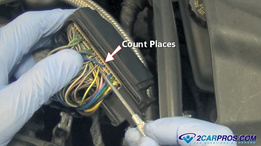
To make sure you are testing the correct wire count the places in the connector
from one end or the other, in this case it is 8 places. This is so when you turn
the connector over you know which terminal to test from.
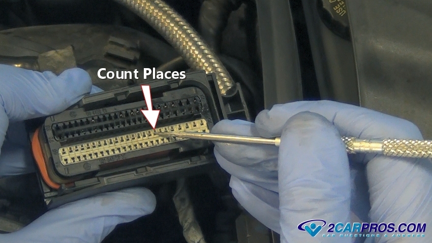
Now turn the connector over and count from the end that you referenced. This
will be the terminal used for testing.
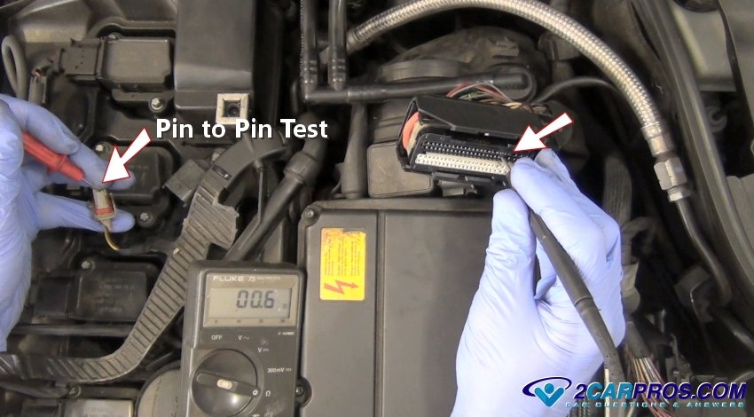
Now, take your voltmeter and switch it to ohms. This will test the resistance
in the wire if any, the idea is to have 0. Connect the probes to either end of the
wiring connectors, the meter will show the resistance in the connection. In this
case the reading is .6 which is next to nothing and acceptable so the wire is okay.
(When testing roll "twist" the test leads in the terminal to ensure proper connection
for a correct reading). If the ohms reading is above 1.5 there is a problem with
the wire and it needs replacement. This is called a pin to pin test. When testing
try and wiggle the wires around while holding the test leads steady, this will simulate
engine vibrating which can help find intermittent shorts, you might need a helper
for this. (While performing this test one of the wires in the circuit was found
to be bad, replacement of the wire fixed the problem).
Questions?
Our certified technicians are ready to answer wire testing questions for free. We hope you saved money and learned from this guide. We are creating a full set of car repair guides. Please subscribe to our 2CarPros YouTube channel and check back often for new videos which are uploaded regularly.