An ignition system ignites a fuel/air mixture inside the engine's combustion chamber at the optimal moment in the pistons compression stroke. This timing is designed to produce the most power while emitting the least amount of emissions. There are many configurations of ignition systems but all operate on the same principle, create a low energy field and collapse it onto a high energy coil that transfers electrical energy into the secondary ignition system, i.e. coil, wire and spark plug.
The system is activated by the primary ignition system, most use a low voltage trigger system i.e. crankshaft position sensor (CKP). This low voltage system (1.0 to 2.0 volts) is increased to 12 volts by using an amplifier which is located inside of the computer or an externally mounted amplifier. The computer PCM (powertrain control module) controls the engine ignition timing by advancing or retarding the primary trigger signal.
Let's Jump In!
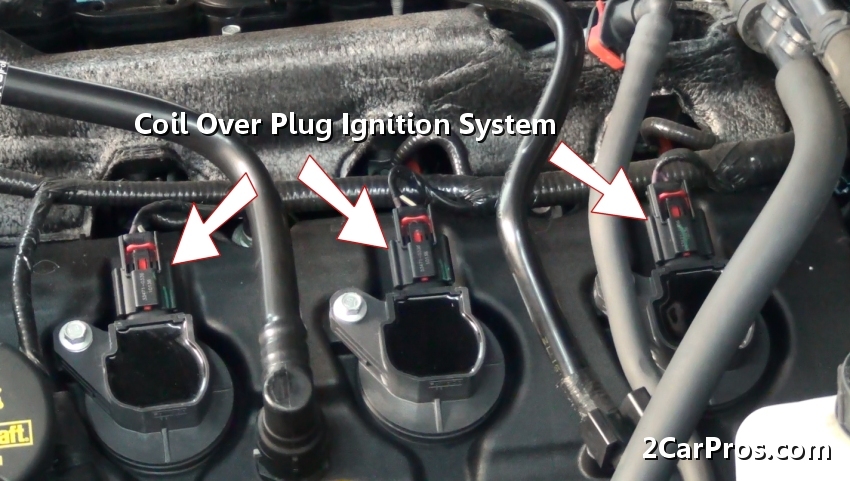
Step 1 - Identify the type of ignition system to be tested, most cars, use a coil over plug (COP) type of system, there are several variations but all work on the same principal.
Step 2 - When checking for a misfire while the engine is still running, the fuel pump must be disabled to avoid accidental ignition discharge. Using the owners manual identify the fuse location.
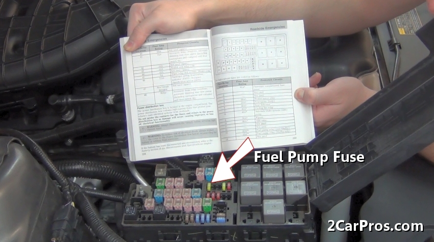
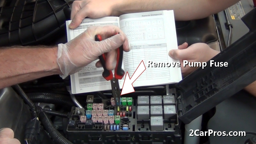
Step 3 - Once the fuse is located use needle nose pliers or a fuse removal tool to remove the fuel pump fuse from the power distribution center (PDC.)
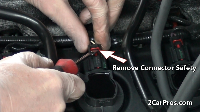
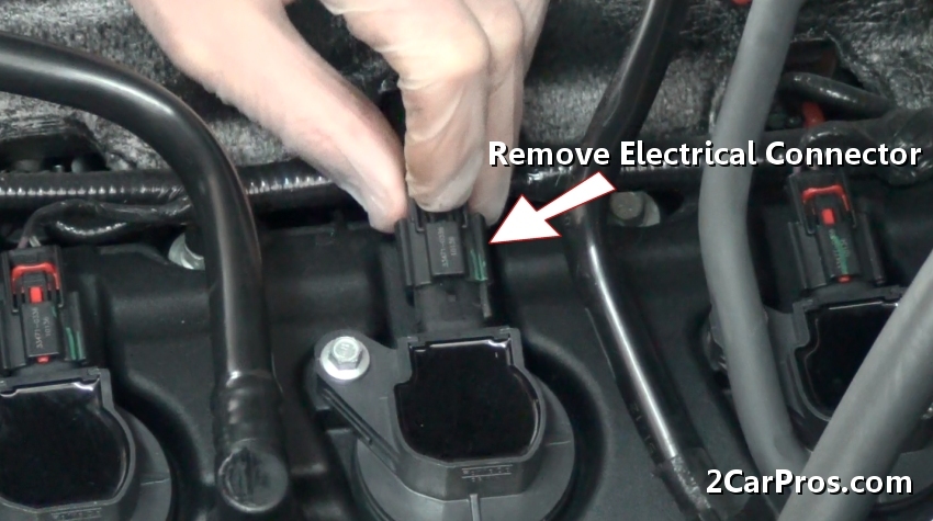
Step 4 - Remove the safety from the coil electrical connector (red.) Some cars are not equipped with this feature.
Step 5 - After the safety has been removed, depress the electrical connector tab to remove the connector from the coil assembly.
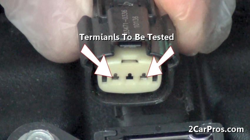
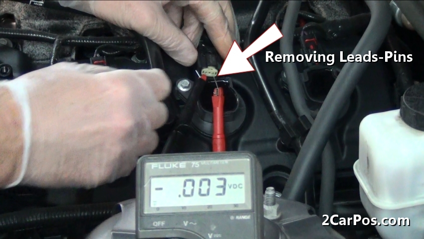
Step 6 - Once the connector has been removed, located both terminals to be used for testing.
Step 7 - Because these terminals are small in size, sometimes a paperclip or small wire can be inserted into the connector terminals which makes testing easier.
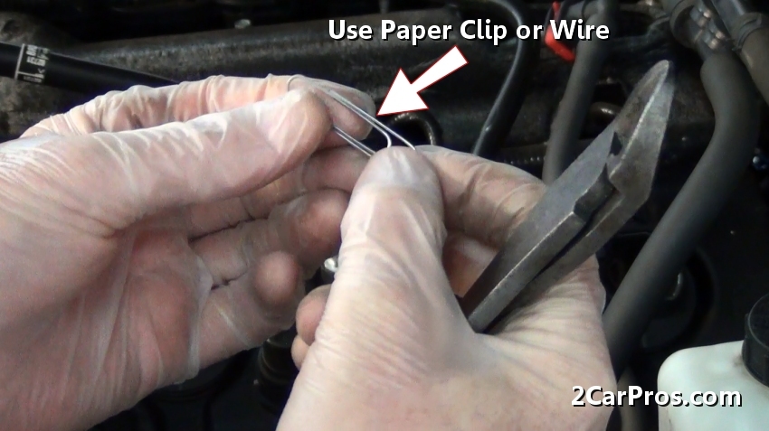
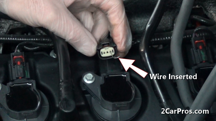
Step 8 - After cutting the paperclip or wire, insert a piece into each terminal, do not allow the wires to contact each other, this could cause damage to the computer.
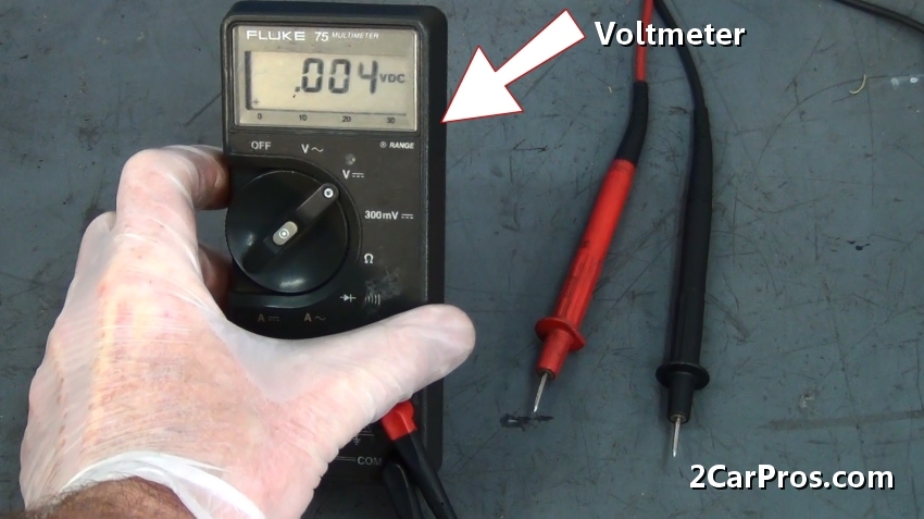
Step 9 - Once both terminals have been prepared, use a voltmeter set to the DC voltage setting. Also install alligator clips to the leads to ensure a good connection.
Watch the Video!
Please watch this video of the job being done, then continue down the guide to glean additional helpful information.
Step 10 - Next, using the voltmeter lead clips, attach them to the paperclip wires, polarity doesn't need to be observed. (Note: Do not allow the leads to connect during the test.)
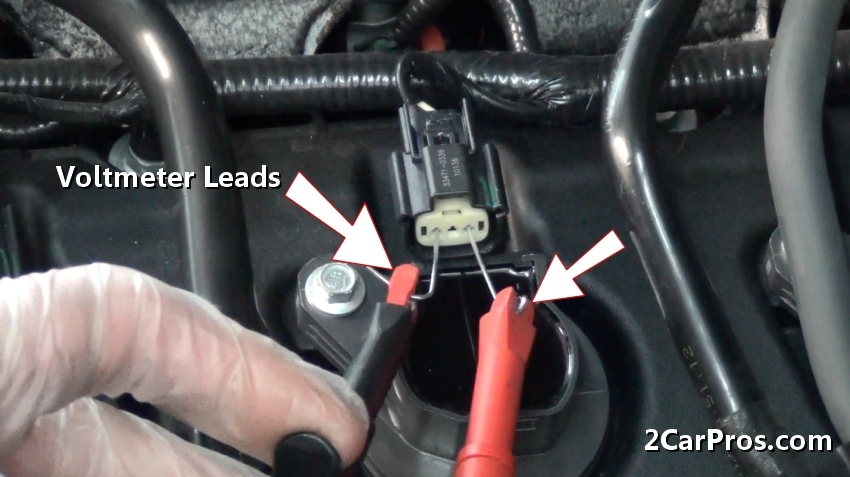
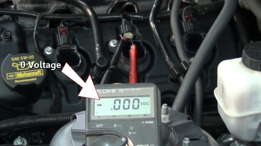
Step 11 - After connecting the leads, turn the ignition key to the "ON" position without cranking the engine. The voltage observed should be 0.
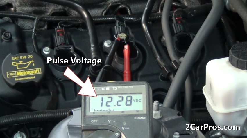
Step 12 - Then, crank the engine over while observing the meter, (engine should not start) the meter should pulsate between 0 and 12 volts. This is confirmation that the computer coil driver is sending signal to the coil for spark and that the ignition system is working. If no voltage is observed while the additional coils on the system operate, check for bad wiring, or computer. If none of the coil triggers operate suspect a crankshaft angle sensor (CKS), or computer control relay.
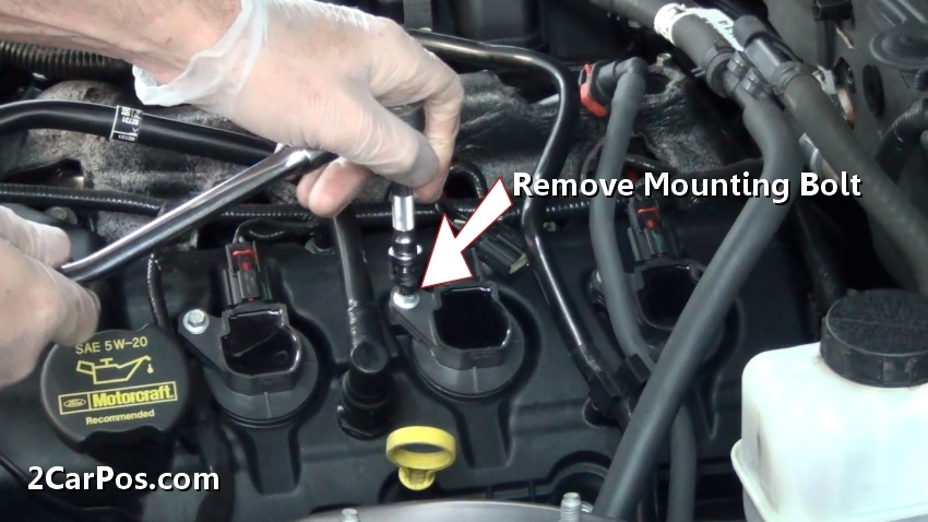
Step 13 - Once this portion of the test is complete, remove the voltmeter leads and test pins from the coil electrical connector.
Step 14 - With the electrical connector disconnected, remove the ignition coil mounting bolt.
Step 15 - After the mounting bolt has been removed, gently lift the coil from the plug well.
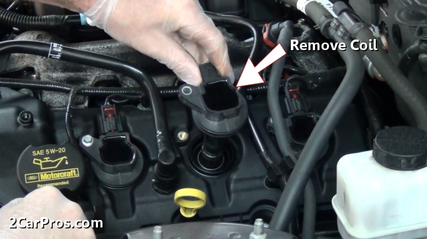
Step 16 - After gently removing the coil from the spark plug well, insect the coil for any broken pieces or cracks in the housing which are an indication of failure.
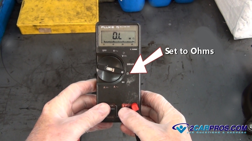
Step 17 - This next test will need a voltmeter set to ohms.
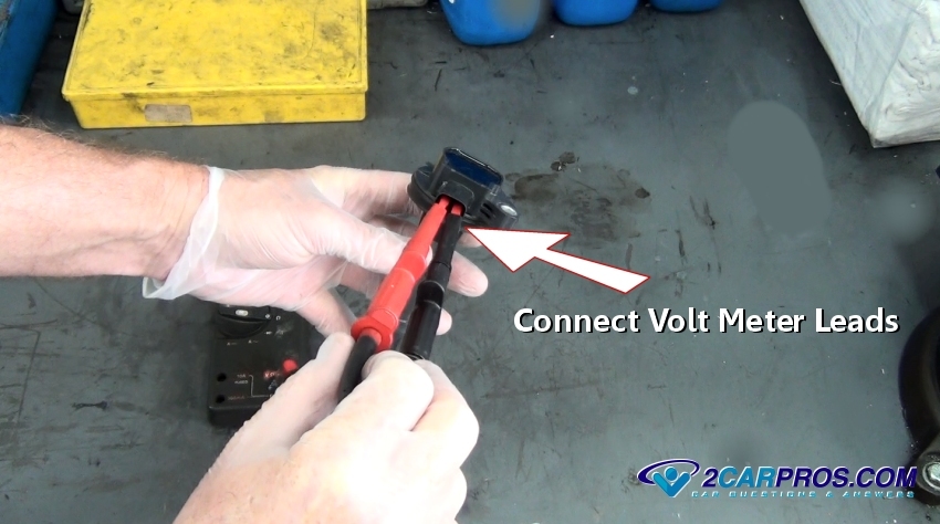
Step 18 - With the coil removed, attach the voltmeter leads to either coil terminal ( small wire connector.)
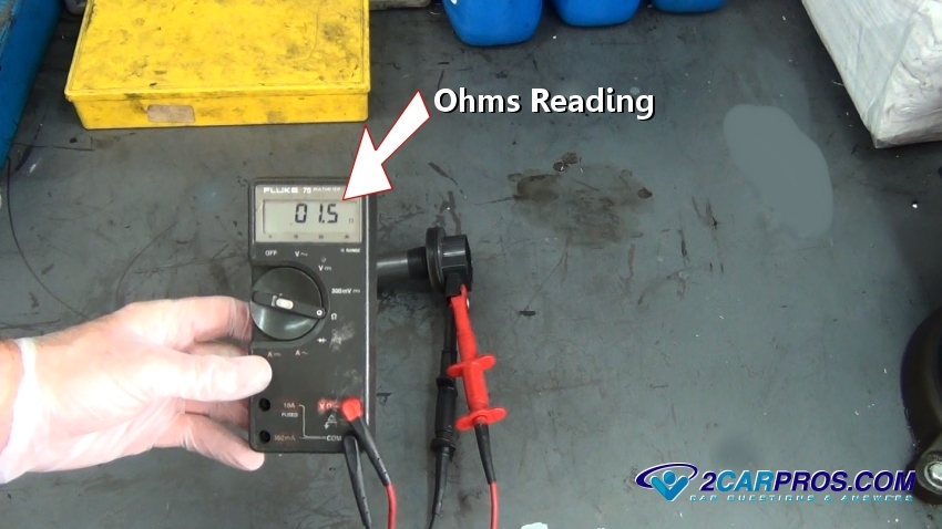
Step 19 - Once the volt meter is connected obtain the reading provided, if this ignition coil was bad the reading would much higher.
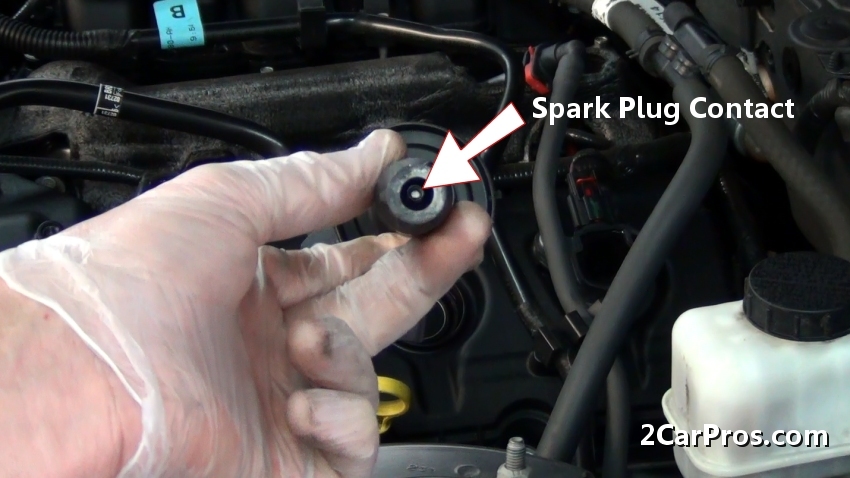
Step 20 - After reconnecting the ignition coil to the wiring harness, observe the electrical contact which contacts the spark plug.
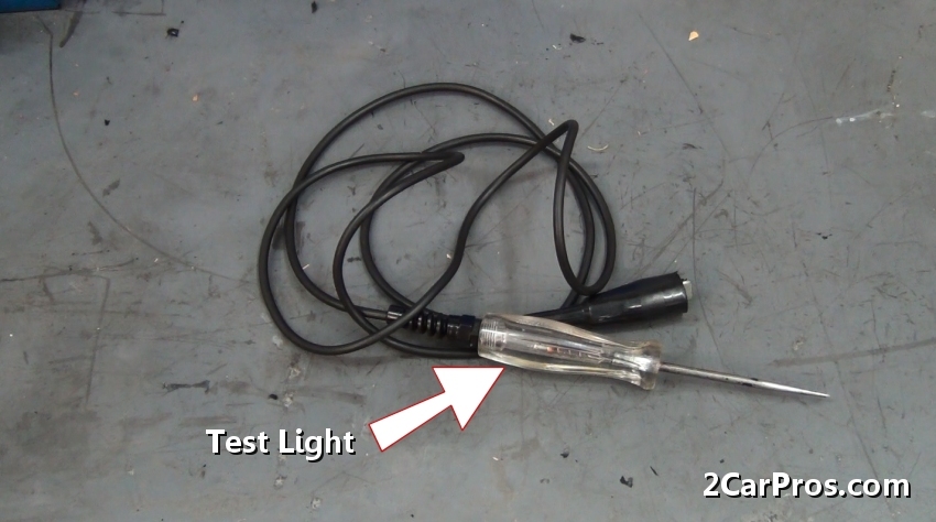
Step 21 - For this portion of the test, a circuit test light is needed which is then connected to engine ground.
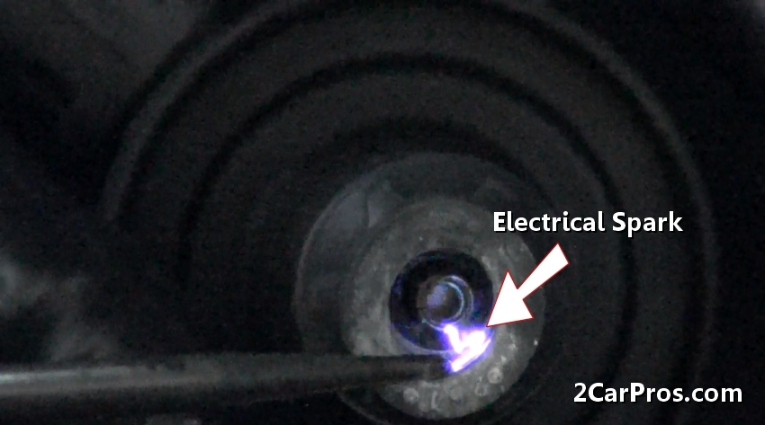
Step 22 - While the grounded test light is creating an air gap between the spark plug contact or terminal, and the tip of the test light.

Step 23 - While keeping hands clear of the test area, have a helper crank the engine over, an electrical spark should be observed if the coil is functioning correctly. If no spark is observed the coil has failed and replacement is required.
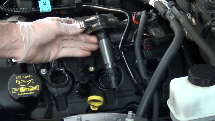
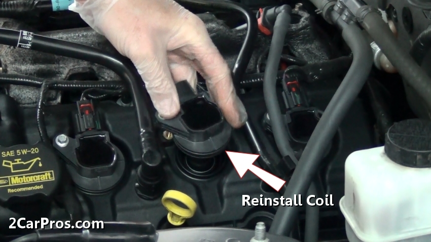
Step 24 - After replacement or testing is complete, gently reinstall the coil into the spark plug well.
Step 25 - Once the coil is in position, install the coil mounting bolt and tighten.
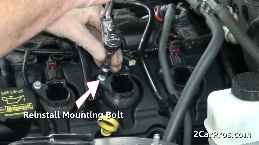
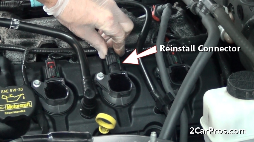
Step 26 - After tightening the coil mounting bolt, reconnect the electrical connector onto the ignition coil. Once the job is complete, start the engine to check coil operation. If the check engine or service engine soon light is illuminated use a code reader to check for codes and reset the system.
Questions?
If you have a car repair question, you can ask the 2CarPros community for help. We hope this guide helped you understand the repair. Please visit our 2CarPros YouTube channel for more helpful repair videos.