Interesting. The idea that it sounded like a heartbeat indicates it is getting spark, but chances are the timing is off. What is going to tell us if it is a timing issue is a compression test.
If you decide to replace the fuel pump, here are the directions. I will start with tank removal and yes, there are two filters in the tank.
_______________________________
2008 Mazda 3 L4-2.3L
Fuel Tank Removal and Installation
Vehicle Powertrain Management Fuel Delivery and Air Induction Fuel Tank Service and Repair Removal and Replacement Fuel Tank Removal and Installation
FUEL TANK REMOVAL AND INSTALLATION
FUEL TANK REMOVAL/INSTALLATION[LF, L3]
WARNING:
- Repairing a fuel tank containing fuel is dangerous. Explosion or fire may cause death or serious injury. Always properly steam clean a fuel tank before repairing it.
- A person charged with static electricity could cause a fire or explosion, resulting in death or serious injury. Before draining fuel, make sure to discharge static electricity by touching the vehicle body.
1. Park the vehicle on a level surface.
2. Follow "BEFORE SERVICE PRECAUTION" before performing any work operations to prevent fuel from spilling from the fuel system. (See BEFORE SERVICE PRECAUTION[LF, L3].) See: Fuel Pressure Release > Procedures > Before Service Precaution
3. Drain the fuel from the fuel tank using the following procedure:
1. Disconnect the quick release connector (in the engine compartment).
2. Attach a long hose to the disconnected fuel pipe and drain the fuel into a proper receptacle.
3. Start the fuel pump using the following procedure:
Using M-MDS
pic 1
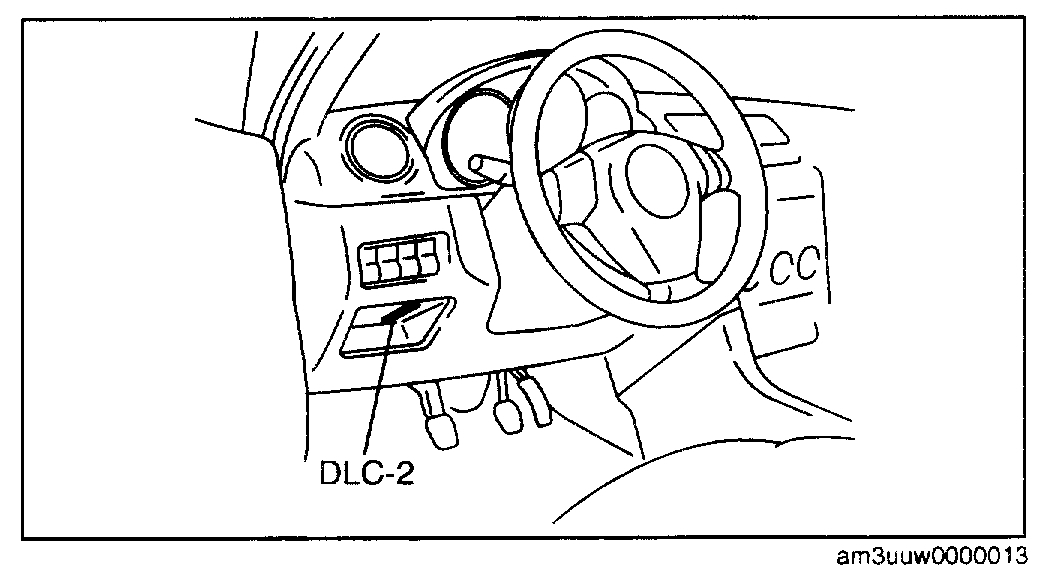
1. Connect the M-MDS to the DLC-2.
2. Start the fuel pump using the "FP" simulation function.
Without using M-MDS
1. Disconnect the negative battery cable.
Pic 2
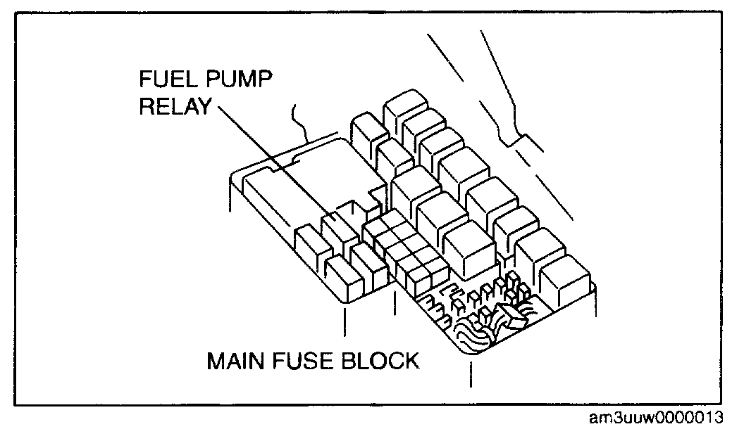
2. Remove the fuel pump relay.
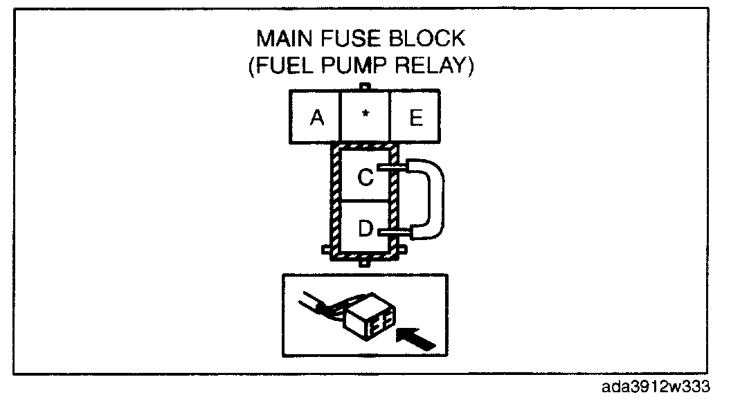
CAUTION: Be careful to short the specified terminal as shorting the wrong terminal of the main fuse block may cause a malfunction.
Pic 3
3. Using a jumper wire, short fuel pump relay terminals C and D and connect the negative battery cable to start the fuel pump.
CAUTION: The fuel pump may malfunction if it is operated without any fuel in the fuel tank (fuel pump idling). Constantly monitor the amount of fuel being discharged and immediately stop operation of the pump when essentially no fuel is being discharged.
4. When essentially no fuel is being discharged from the hose, stop the fuel pump using the following procedure:
Using M-MDS
1. Stop the fuel pump using the "FP" simulation function.
Without using M-MDS
1. Disconnect the negative battery cable to stop the fuel pump.
4. Disconnect the negative battery cable, (using M-MDS)
5. Remove the rear seat cushion.
6. Remove the service hole cover.
7. Disconnect the fuel pump unit connector.
8. Remove the charcoal canister protector.
9. Lower the main silencer so that the insulator can be removed.
10. Remove the insulator.
11. Remove the rear under cover (LH).
12. Remove in the order indicated in the table.
13. Install in the reverse order of removal.
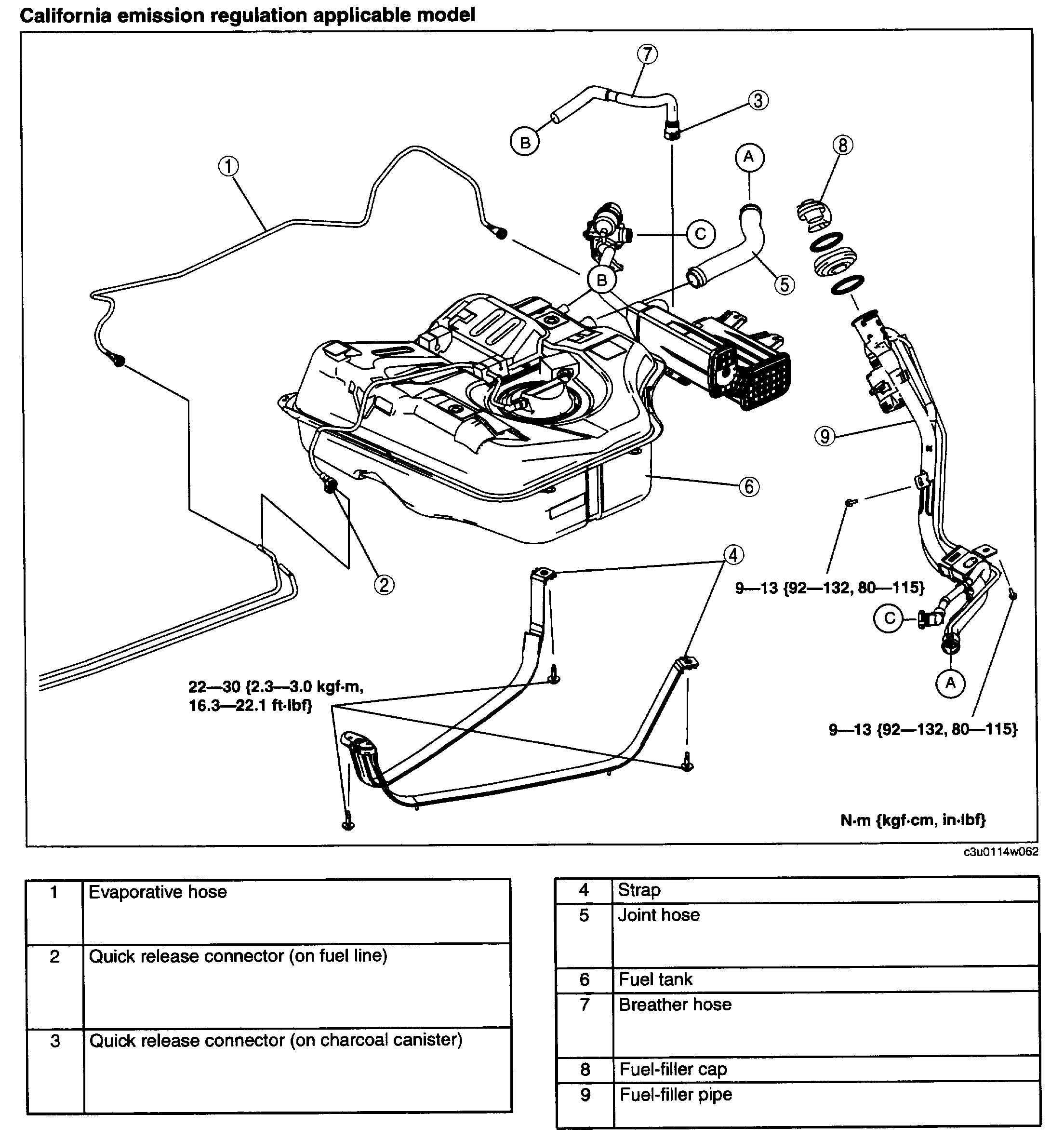
California Emission Regulation Applicable Model
pic 4
14. Inspect all parts by performing "AFTER SERVICE PRECAUTION". (See AFTER SERVICE PRECAUTIONS[LF, L3].) See: Fuel Pressure Release > Procedures > After Service Precaution
California emission regulation applicable model
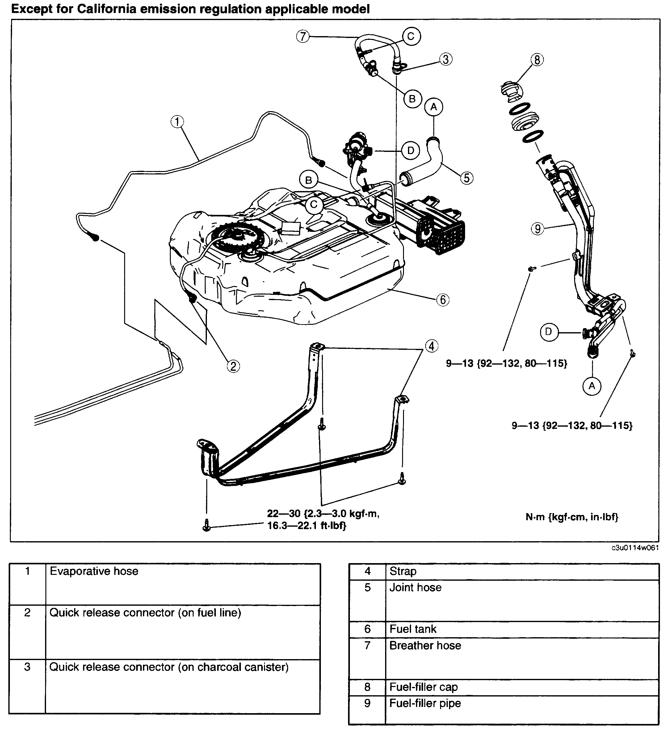
Except For California Emission Regulation Applicable Model
pic 5
Except for California Emission Regulation Application Model
Evaporative Hose Removal/Installation Note
- Refer to the "QUICK RELEASE CONNECTOR (EMISSION SYSTEM) REMOVAL/INSTALLATION" to disconnect the quick release connector of the front side of the fuel tank.
- Refer to the "QUICK RELEASE CONNECTOR (EMISSION SYSTEM) REMOVAL/INSTALLATION" to disconnect the quick release connector connected to the charcoal canister.
- Refer to the "QUICK RELEASE CONNECTOR (EMISSION SYSTEM) REMOVAL/INSTALLATION" to reconnect the quick release connector of the front side of the fuel tank.
- Refer to the "QUICK RELEASE CONNECTOR (EMISSION SYSTEM) REMOVAL/INSTALLATION" to reconnect the quick release connector connected to the charcoal canister.
Joint Hose Removal Note
1. Remove the fuel-filler pipe installation bolt.
2. Loosen the tie band connecting with the fuel tank.
3. Pull down the fuel-filler pipe to disconnect the joint hose.
Breather Hose Removal Note
- Except for California emission regulation applicable model, refer to the "QUICK RELEASE CONNECTOR (EMISSION SYSTEM) REMOVAL/INSTALLATION)" to disconnect the quick release connector connecting to the fuel shut-off valve.
Fuel-filler Pipe Removal Note
1. Remove the rear tire (RH).
2. Remove the rear mudguard (RH).
3. Support the rear crossmember using a transmission jack.
4. Remove the rear shock absorber (RH) lower bolts.
5. Loosen the rear crossmember installation nuts (6 locations) and lower the rear crossmember 30 mm 1.2 in.
6. Remove the fuel-filler pipe.
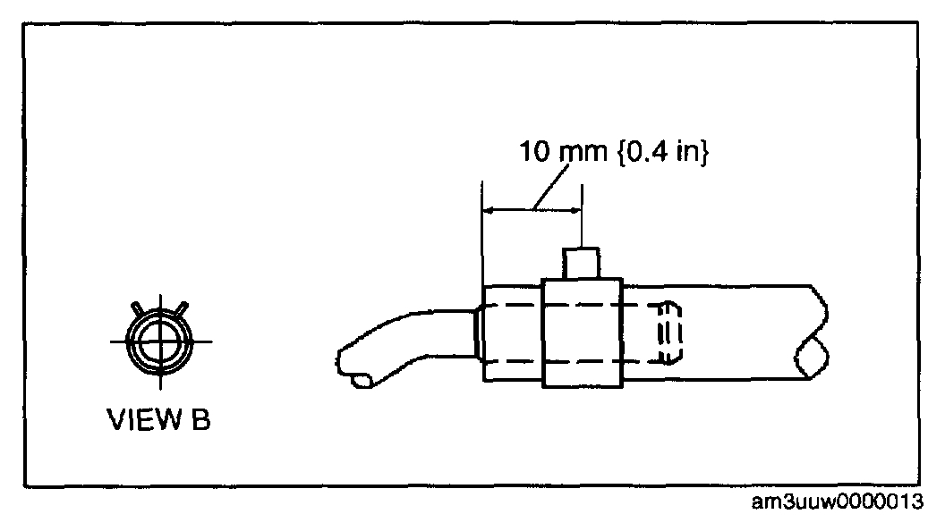
Breather Hose Installation Note
pic 6
California emission regulation applicable model
- Connect the breather hose connecting with the fuel tank and clamp as shown in the figure.
Except for California emission regulation applicable model
- Refer to the "QUICK RELEASE CONNECTOR (EMISSION SYSTEM) REMOVAL/INSTALLATION)" to reconnect the quick release connector connecting to the fuel shut-off valve.
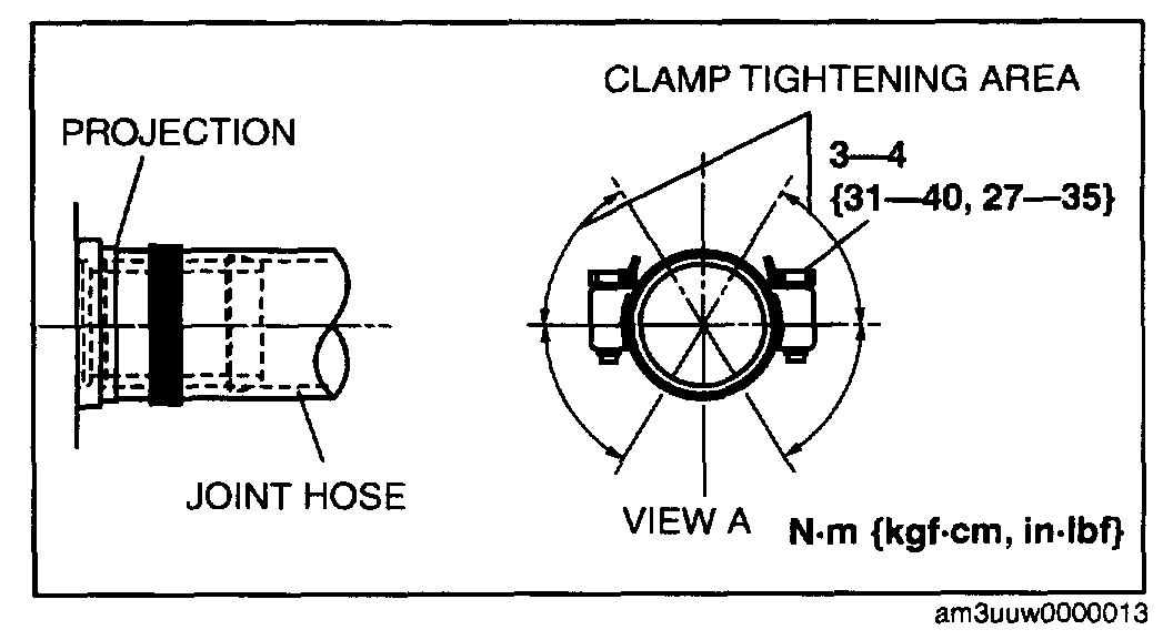
Joint Hose Installation Note
pic 7
1. Install the joint hose and clamp as shown in the figure.
_______________________________
2008 Mazda 3 L4-2.3L
Fuel Pump Unit Removal/Installation
Vehicle Powertrain Management Fuel Delivery and Air Induction Fuel Pump Service and Repair Removal and Replacement Fuel Pump Unit Removal/Installation
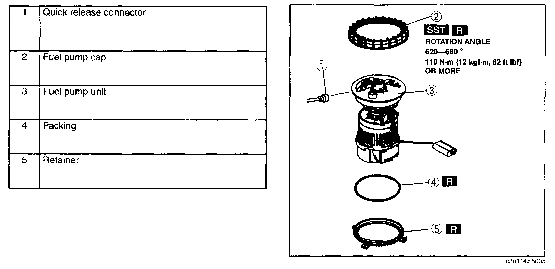
FUEL PUMP UNIT REMOVAL/INSTALLATION
FUEL PUMP UNIT REMOVAL/INSTALLATION[LF, L3]
WARNING:
- Fuel is very flammable liquid. If fuel spills or leaks from the pressurized fuel system, it will cause serious injury or death and facility breakage. Fuel can also irritate skin and eyes. To prevent this, always complete the "Fuel Line Safety Procedure", while referring to "BEFORE SERVICE PRECAUTION".
- Fuel is very flammable liquid. If fuel spills or leaks from the pressurized fuel system, it will cause serious injury or death and facility breakage. Fuel can also irritate skin and eyes. To prevent this, before performing the fuel pump unit removal/installation, always complete the "Fuel Leak Inspection After Fuel Pump Unit Installation".
NOTE: Gasket must be replaced anytime fuel pump is removed or replaced.
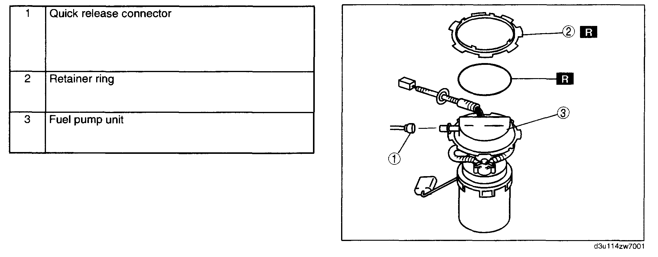
California Emission Regulation Applicable Model
1. Follow "BEFORE SERVICE PRECAUTION" before performing any work operations to prevent fuel from spilling from the fuel system. (See BEFORE SERVICE PRECAUTIONS, L3].) See: Fuel Pressure Release > Procedures > Before Service Precaution
2. Disconnect the negative battery cable.
3. Remove the fuel tank.
4. Remove in the order indicated in the table.
5. Install in the reverse order of removal.
Pic 8
6. Inspect all related parts by performing "AFTER SERVICE PRECAUTION". (See AFTER SERVICE PRECAUTIONS[LF, L3].) See: Fuel Pressure Release > Procedures > After Service Precaution
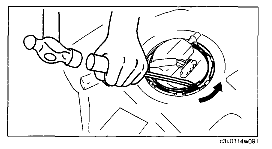
Retainer ring removal note
pic 9
1. Remove the retainer ring by tapping a retainer ring projection using a flathead screwdriver as shown in the figure.
Pic 10
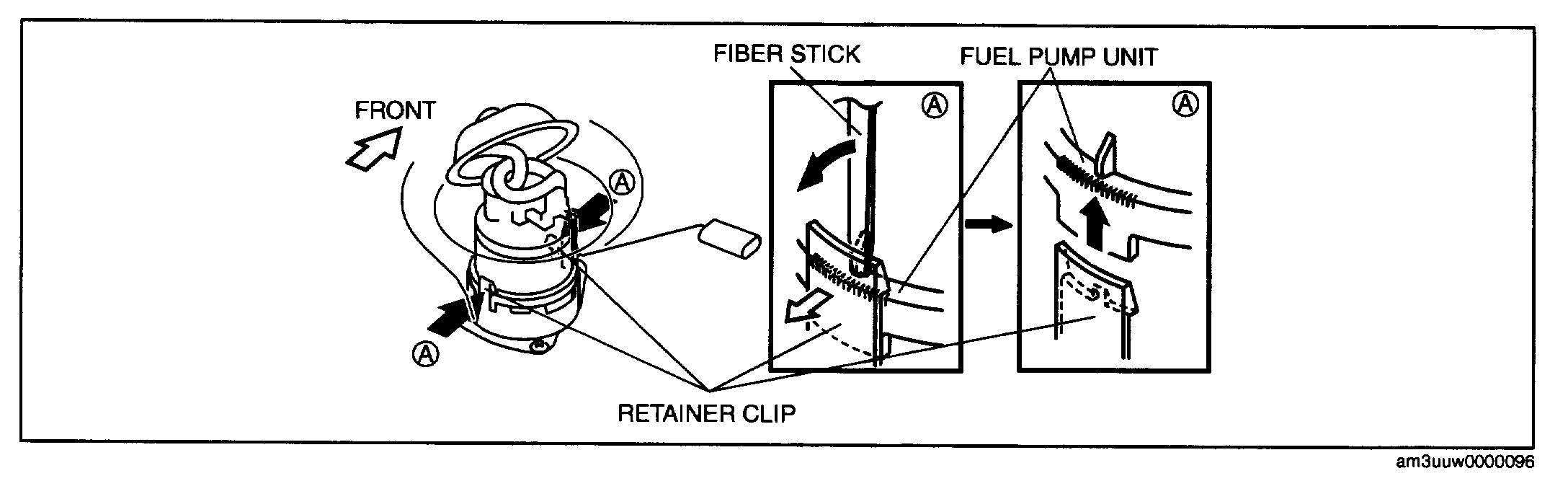
Fuel pump unit removal note
NOTE: The fuel pump unit is secured by the two retainer clips with the bracket on the bottom surface of the fuel tank.
Pic 11
1. Using a fiber stick, disengage the retainer clips until the pump can be removed
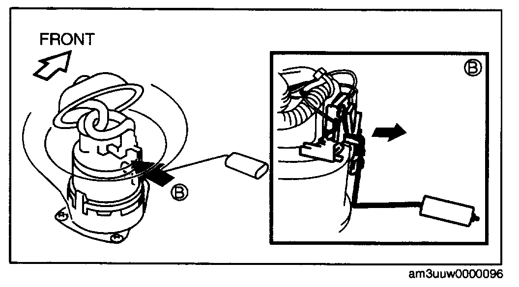
2. Remove the fuel pump gauge connection area from the fuel pump unit.
3. Set the fuel pump gauge out of the way and remove the fuel pump unit from the fuel tank.
Fuel pump unit installation note
NOTE: Keep the fuel pump gauge set out of the way.
1. Insert the fuel pump unit to the fuel tank.
2. Install the fuel pump gauge to the fuel pump unit.
3. Engage the retainer clips with the fuel pump unit.
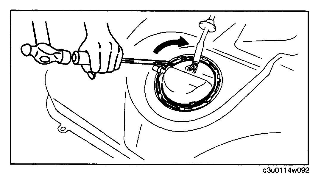
Retainer ring installation note
pic 12
1. Tap a retainer ring projection using a flathead screwdriver as shown in the figure and tighten the retainer until it is fixed in place.
Except For California Emission Regulation Applicable Model
1. Follow "BEFORE SERVICE PRECAUTION" before performing any work operations to prevent fuel from spilling from the fuel system. (See BEFORE SERVICE PRECAUTIONS, L3].) See: Fuel Pressure Release > Procedures > Before Service Precaution
2. Disconnect the negative battery cable.
3. Remove the fuel tank.
4. Remove in the order indicated in the table.
5. Install in the reverse order of removal.
Pic 13
6. Inspect all related parts by performing "AFTER SERVICE PRECAUTION". (See AFTER SERVICE PRECAUTIONS[LF, L3].) See: Fuel Pressure Release > Procedures > After Service Precaution
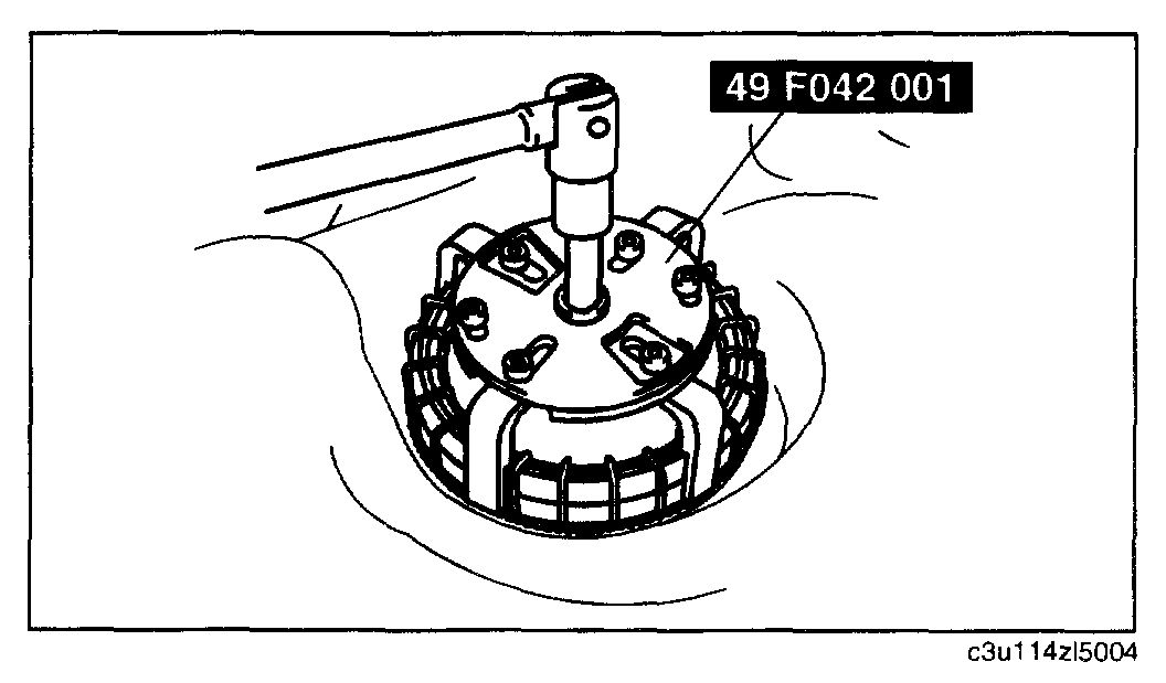
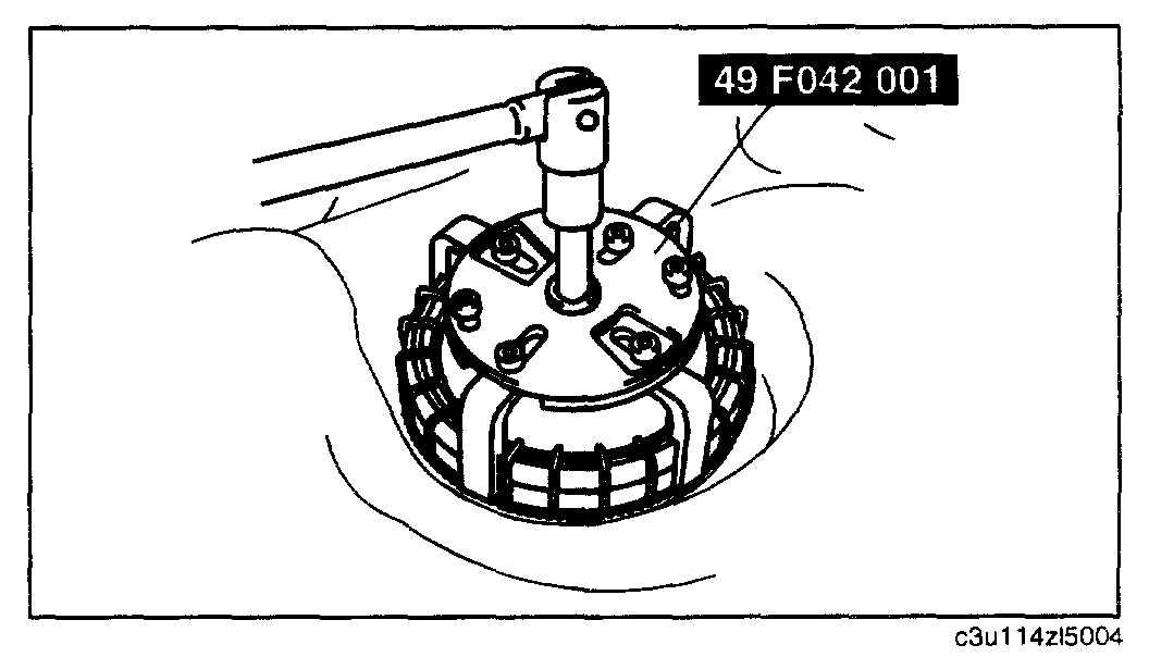
Fuel pump cap removal note
CAUTION: The fuel pump cap could be damaged if the SST is used with any gap between the cap and the SST. Securely attach the SST so that there is no gap between the SST tabs and the side of the cap.
Pic 14
1. Remove the fuel pump cap using the SST.
Fuel pump cap installation note
WARNING: Make sure there is no foreign material on each of the parts. If there is foreign material on the parts, the fuel pump unit cannot be assembled correctly, which could result in fuel leakage.
NOTE: The fuel pump unit will rotate and cannot be secured in the specified position if there is any gasoline on the gasket. Thoroughly wipe away all gasoline from the gasket.
1. Replace the packing, fuel pump cap and the retainer with new parts.
CAUTION: New parts can deform depending on the temperature. If the parts deform, the fuel pump unit cannot be assembled correctly, which could result in fuel leakage. Therefore, keep new parts at room temperature for the specified period of time to stabilize the shape.
2. Leave new parts inside for the following period of time:
Stand-by time 12 h or more
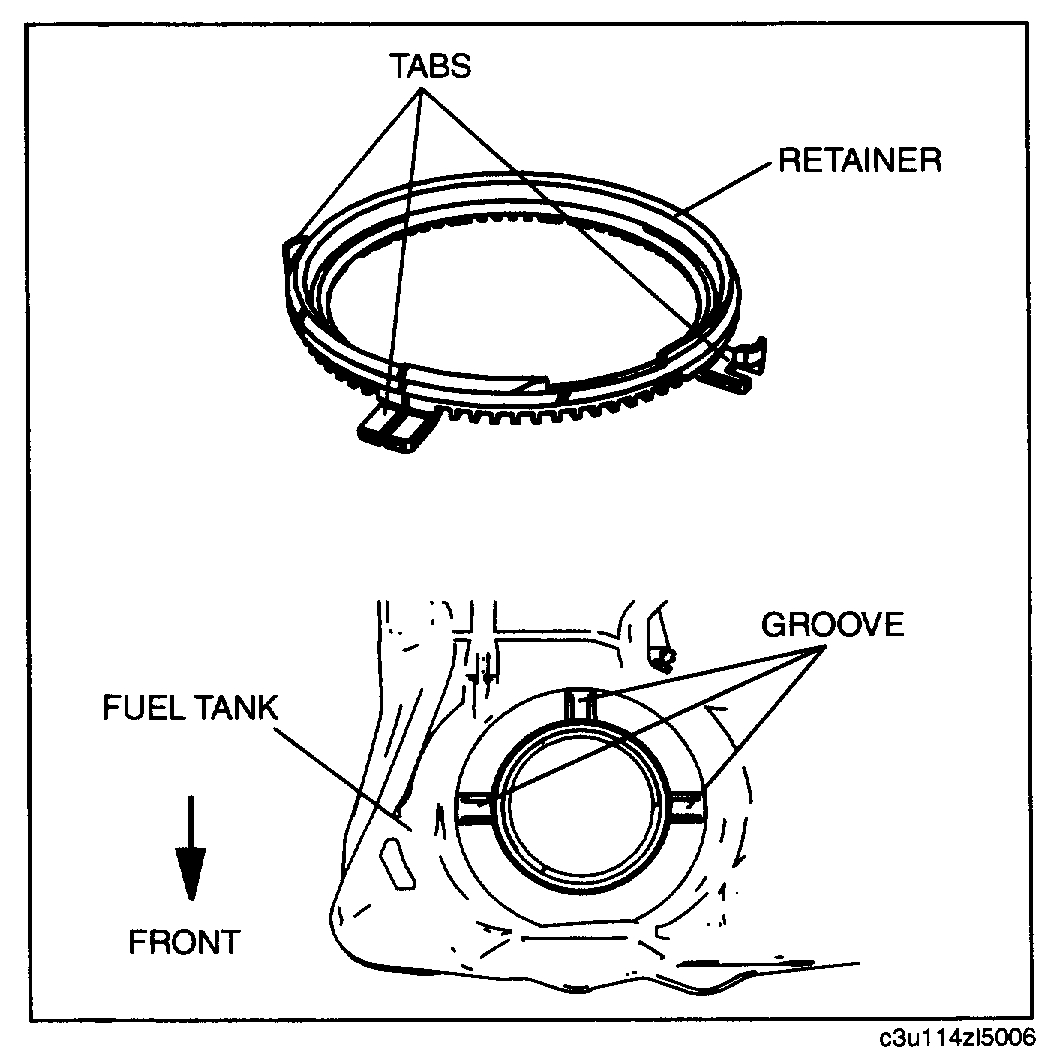
pic 15
3. Install a new retainer to the fuel tank.
1. Align the retainer tabs (3 locations) with the fuel tank grooves.
2. Verify that the tabs are inserted into the grooves and the retainer is installed correctly.
3. Verify the retainer is not damaged.
4. Install a new packing to the fuel tank.
1. Verify the packing groove is clean and free of foreign material.
2. Install the packing to the fuel tank so that it is inserted into the fuel tank grooves.
CAUTION: Install the fuel pump unit to the fuel tank being careful not to bend the fuel sender unit arm. If the arm is bent, the fuel sender unit will not operate correctly.
5. Install the fuel pump unit to the fuel tank.
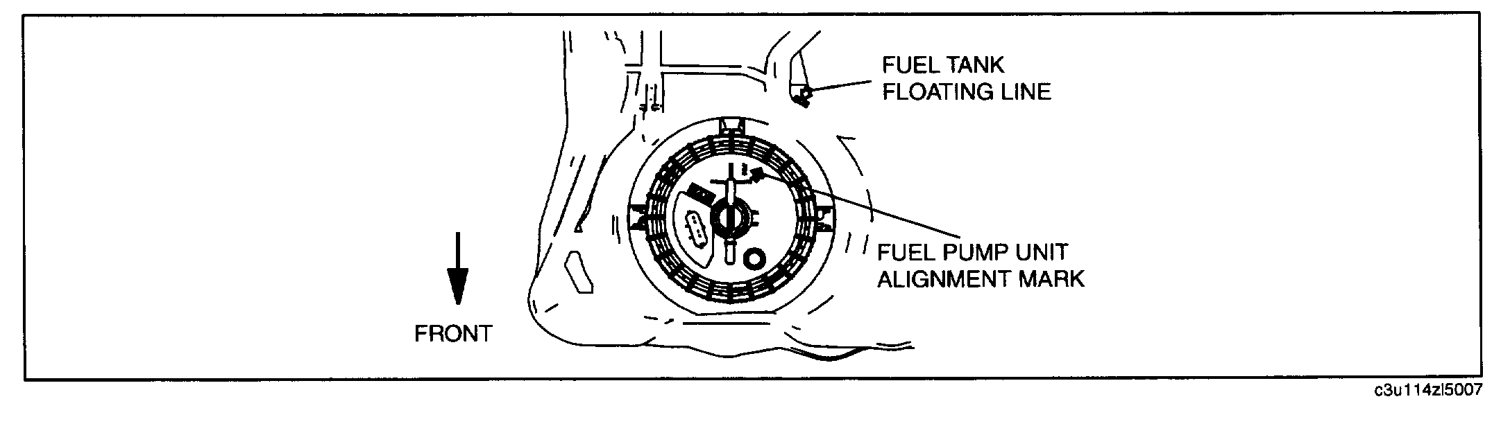
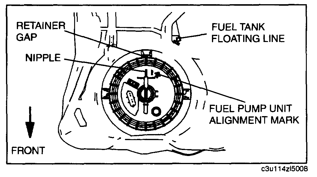
Pic 16
1. Align the fuel pump unit alignment mark and the floating line on the fuel tank.
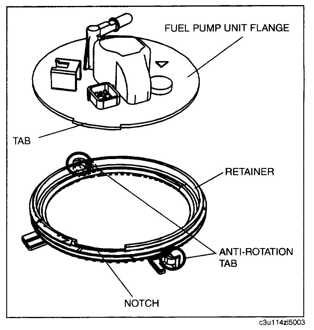
Pic 17
2. Verify the tab on the fuel pump unit flange with the notch on the retainer.
Pic 18
6. Set on a new fuel pump cap.
1. Apply downward force (push down) on the center of the fuel pump unit flange.
NOTE:
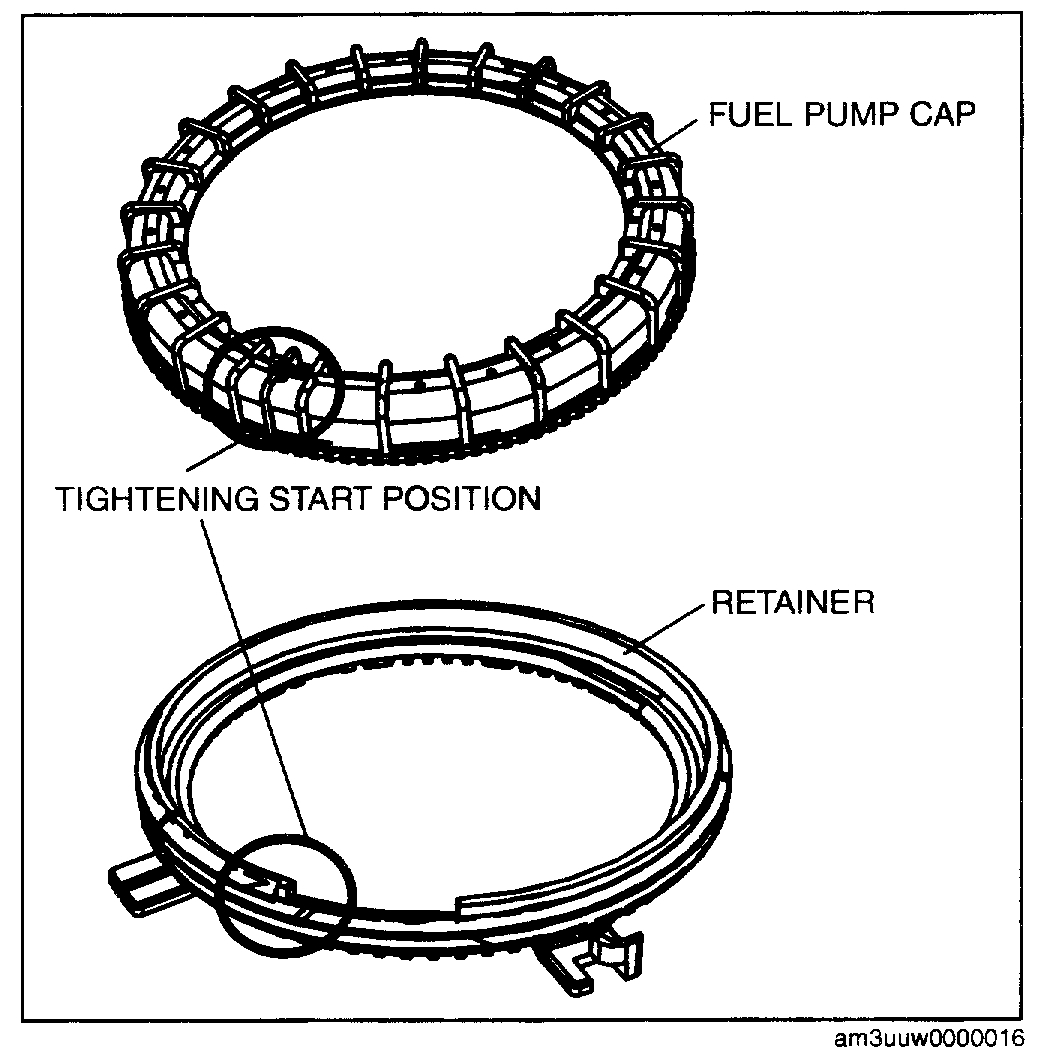
- Align the fuel pump cap with the tightening start position of the retainer and tighten the fuel pump cap with the start position as 0 °.
- The fuel pump cap tightening start position is the position where the spaces between the ribs become narrow. The retainer tightening start position is the notch position.
2. Align the tightening start position on the fuel pump cap and the tightening start point of the retainer.
WARNING:
- No grease or lubrication allowed on parts during installation. Parts could slide or they cannot be tightened to the specified torque. As a result, fuel leakage could occur.
- When tightening the fuel pump cap, be careful that the points indicated below have not deviated. If there is deviation, the fuel pump unit cannot be installed correctly, which could result in fuel leakage.
- The fuel pump unit alignment mark and the floating line on the fuel tank
- The fuel pump unit nipple and the retainer gap
pic 19
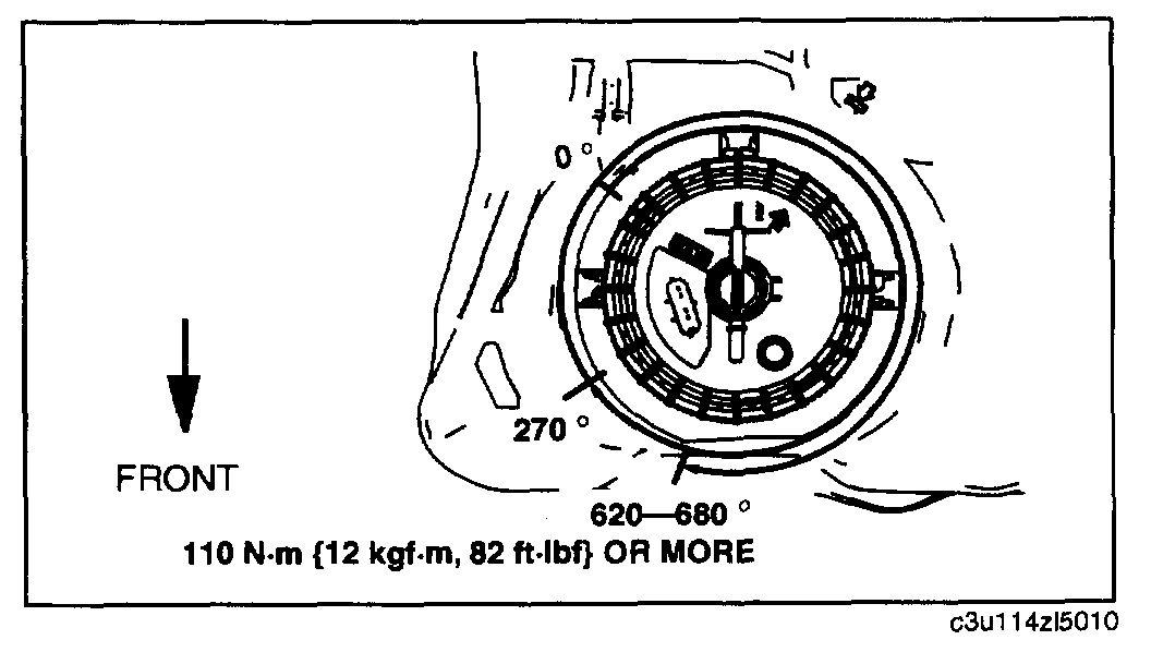
7. Tighten the fuel pump cap.
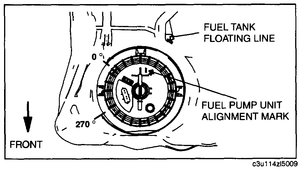
Pic 20
1. Tighten the fuel pump cap by hand to the specified angle or more until the flange is fixed.
Fuel pump cap rotation angle
270 ° or more
2. Verify that the fuel pump cap is tightened correctly.
1. The gap between the bottom of the fuel pump cap and the tank surface is even all around.
- If the fuel pump cap is not tightened uniformly, loosen it by hand and reinstall it.
Pic 21
3. Install the SST.
NOTE The fuel pump cap rotation angle is the angle from the 0 ° position. The angle tightened to using the SST includes the angle tightened by hand.
Pic 23
4. Tighten the fuel pump cap to the specified torque and to the specified angle or more.
Fuel pump cap rotation angle
620 - 680 °
Fuel pump cap tightening torque
110 N-m 12 kgf-m, 82 ft-lbf or more
5. Verify that the fuel pump cap is tightened correctly.
1. The gap between the top of the fuel pump unit flange and the fuel pump cap is even all around.
- If it is not tightened uniformly, re-install it using the following procedure.
2. The gap between the fuel pump unit and fuel tank is even all around.
- If it is not tightened uniformly, re-install it using the following procedure.
3. Verify that the fuel pump unit alignment mark and the floating line on the fuel tank are aligned.
- If they are not aligned, re-install it using the following procedure.
Pic 23
4. Verify that the fuel pump unit nipple and the retainer gap are aligned.
- If it is not aligned, re-install using the following procedure.
1. Install the SST.
2. Remove the fuel pump cap, fuel pump unit, packing, and retainer.
3. Verify that the retainer is not damaged.
- If both of the retainer anti-rotation tabs are broken, replace it with new one.
4. Return to Step 2 and re-install.
_____________________
Before doing any of this work, check compression.
Let me know what you find.
Joe
Images (Click to make bigger)
Sunday, March 15th, 2020 AT 6:11 PM