No power to starter solenoid

Tiny
HAGMAN
  • MEMBER
  • 2010 DODGE RAM
  • 5.7L
  • V8
  • 4WD
  • AUTOMATIC
  • 78,000 MILES
Hello,

I'm a little stumped as electrical is not my strong subject. My truck listed above is a 1500. The truck will not start. The TIPM Starter Relay is a 4-Pin design and I have verified that power is getting to the correct relay cavity. However, when I have someone try and crank the engine, there is no power going from the starter relay to the starter solenoid. The starter is in good working order. I have verified the relay is good and even tried a new relay in the socket, and no go? I'm looking for any advice to point me in the correct direction to fix this. Thanks for your time.
Tuesday, May 24th, 2022 AT 11:58 AM

35 Replies

Tiny
BORIS K
  • MECHANIC
  • 762 POSTS
Hello,

The first thing to check is if the relay is being activated when trying to crank the engine?
There should be an audible click from the relay.

Have you tried starting the engine in neutral and park?

If there is a click from the relay then the next thing to check is if there is 12V being transmitted out of the TIPM on connector C5(brown) pin 1, yellow/grey wire. See diagram attached.

This check can be done by using a test light or a voltmeter.

https://www.2carpros.com/articles/how-to-use-a-test-light-circuit-tester
or
https://www.2carpros.com/articles/how-to-use-a-voltmeter

If there is 12V at this pin and still nothing at the starter solenoid, then next check the wire between the TIPM and the solenoid.

https://www.2carpros.com/articles/how-to-check-wiring

Hope this helps.

Cheers, Boris
Was this
answer
helpful?
Yes
No
Wednesday, May 25th, 2022 AT 3:27 AM
Tiny
HAGMAN
  • MEMBER
  • 23 POSTS
Thank for the info Boris. I'll do the checks and get back to you with the findings. It might be a couple days due to rain in the area. Thanks-
Was this
answer
helpful?
Yes
No
-1
Wednesday, May 25th, 2022 AT 7:14 AM
Tiny
HAGMAN
  • MEMBER
  • 23 POSTS
Boris,
I had a tiny break in the rain and did one test using a tool similar to a Power Probe and probed the 4 pin cavities of the Starter Relay- (KOEO). Here's what I got:
1 pin had constant 12V
2 other pins had no voltage
1 pin (pin that supplies power to starter solenoid) showed ground/green (0 Volts)? Is this normal for this pin? I'm no expert, but if its showing ground, then there must be a short somewhere on that wire? Please advise if I'm wrong or in the right direction. Thanks Again and have a good weekend.
Was this
answer
helpful?
Yes
No
Thursday, May 26th, 2022 AT 9:57 AM
Tiny
CARADIODOC
  • MECHANIC
  • 33,752 POSTS
You should start with the quick test described by Boris K. Feel if the starter relay clicks when a helper turns the ignition switch to "crank". If it does, that eliminates 90 percent of the circuitry as suspects.

With older starter systems, they can be broken down into four parts, each with a corresponding terminal in the starter relay's socket. In this case at least two computers were added so some tests aren't possible. The constant 12 volts you found on the supply circuit is correct. The ground you found on the circuit going to the starter solenoid is also correct. The apparent ground your probe is finding is the extremely low resistance of the starter solenoid. When we do these tests with a standard test light with a simple bulb inside, we find 12 volts all the time on terminal 30, and 12 volts on terminal 86 only with the ignition switch in the "crank" position.

For the other two terminals, we're looking for ground, so the test light's clip lead must be moved to the battery's positive post. In older vehicles, terminal 85 reads continuity to ground through the neutral safety switch. Terminal 87 will read to ground, (very low resistance), as I mentioned, through the starter solenoid.

In 2010 through 2022 models, the tests for terminals 85 and 86 are not valid because there's all kinds of electronic switching circuitry we can't activate manually.

The way to diagnose this system is with a scanner to see what the various computers are seeing. Most problems are caused by the Totally Integrated Power Module, (TIPM), (under-hood fuse box), which isn't actually a computer module. I had some apart recently for a 2015 model, which is the same, and found it's full of miniature relays that can't be taken apart to clean the contacts. Before you get all "wrapped around the axle" with complicated tests, you might consider substituting a good used TIPM as a test. Boris K will be back shortly to continue helping you.
Was this
answer
helpful?
Yes
No
Thursday, May 26th, 2022 AT 8:39 PM
Tiny
HAGMAN
  • MEMBER
  • 23 POSTS
Thanks, Randy, for your reply. I'll print out what you mentioned and attempt to do further testing. I was not aware that the main feed wire to the starter solenoid should show ground. This is a 4-pin relay. The main power or constant power is directly diagonally across from the power feed so this part should be the control side of the relay, I guess. I always thought the control side powers the coil, then the arm makes contact so power can go through the load side to the device-(starter solenoid)? I've been told that since it's a 4-pin relay, that it does not matter which way the relay plugs in? I will do the steps in sequence to what you and Boris have mentioned and write down my findings and then let you both know what I find. My problem is getting the availability to test equipment since I live out in the back woods, all I have is a cheap scanner, test light and decent multimeter. Thank you, guys, for the help and I will certainly get back with the findings.
Was this
answer
helpful?
Yes
No
Friday, May 27th, 2022 AT 6:19 AM
Tiny
CARADIODOC
  • MECHANIC
  • 33,752 POSTS
Let me clarify what I think you may have been told about relays. To start with, all relays have four terminals. Two are for the contacts that switch the high current on and off. The other two are for the low-current coil that creates the electromagnetic field that moves the contact. Those two high-current contact terminals are interchangeable, with one notable exception. If you look back at the drawing I posted of common relay terminals, the 1"-cube relay uses terminals 30 and 87 for the contacts. Those contacts are called, "normally open" aka "turned off" when the relay is relaxed. When the coil is energized, terminals 30 and 87 are connected together. I didn't label the terminal in between them, but that is terminal 87A. 87A and terminal 30 are connected together when the relay is relaxed, meaning that pair of contacts are "normally closed, aka normally on. We don't talk much about 87A because it is used very little in automotive applications, but it's because either 87 or 87A receive 12 volts from terminal 30, that 30 must be the common terminal, in this case the 12 volt feed.

Regardless, the confusion is with terminals 85 and 86. In a standard, inexpensive relay, those two are also interchangeable. As long as one is grounded and the other gets 12 volts, the relay will energize and pull the movable contact to connect 87 to 30. Where the problem comes in is when that coil is switched off. When an ignition coil is switched on, the magnetic field builds up relatively slowly. That field opposes the current flow causing it to build up, so it takes some time. Once that field is built up fully, and current is switched off, either by opening the breaker points, or turning off a switching transistor, the magnetic field has no choice but to collapse instantly. That rapid collapse cuts across the coil's primary winding and "induces" a huge voltage spike of as much as 300 volts. That is multiplied in the secondary and goes on to fire a spark plug. In this application we want that 300-volt spike and it's the key to how ignition coils operate.

The same thing happens in a relay's coil, but to a much smaller extent. When first energized, current flow through it, and the strength its magnetic field, ramp up relatively slowly, but when switched off, current flow has to stop instantly. The rapid collapse of the magnetic field generates a voltage spike that can easily be harmful to the circuitry that is driving, or running that coil. Switches don't care. They just laugh at those spikes, but if a switching transistor inside a computer module is used, they have a design limit as to how much voltage they can tolerate. The transistor will be permanently shorted if the voltage spike is higher than the limits the transistor can withstand.

The way the voltage spikes are rendered harmless is to use a diode across the relay's coil. A diode is a very simple two-terminal device that is a one-way valve for electrical current flow. It is placed in the circuit backward in this application, so in effect, it isn't even there. Being backward makes it "reverse-biased" or turned off. It does nothing while the relay is energized and turned on. It's when the relay is turned off and the voltage spike is generated that the diode does its thing. The voltage spike is of such a polarity that it "forward-biases" the diode, meaning turns it on. The diode acts like a piece of wire for that instant and shorts out the spike. Current flow always seeks the path of least resistance. In this case it would rather flow easily and harmlessly through the diode rather than through the computer circuitry that could be damaged.

It's because of that internal diode that terminals 85 and 86 can't be switched around. If you use one of these relays to build a custom project and connect the wrong terminal to 12 volts, the diode will be forward biased, (turned on), and act like a short. Lots of smoke or a blown fuse will result.

What I think you may have been told about reversing a relay pertains to some of GM's relays. They only use the basic four terminals, with the two for the contacts on diagonally opposite corners, and the two for the coil in the other two diagonally opposite corners. Even though the terminals are physically slightly off-center, the relay can be installed rotated 180 degrees. The two terminals for the contacts will still be in the same terminals in the socket. Same with the two terminals for the coil. This wouldn't be possible with a diode across the coil. GM uses a resistor instead. Resistors don't have a polarity. They don't totally short out a voltage spike like a diode does. They just dampen it to keep it down to a safe level. These relays can be reversed and will work just fine. The "basing" of Chrysler relays is much more common, but they can't be reversed electrically, and the shape of the terminals prevents them from being reversed physically.

To boil this down, if a relay can be reversed in its socket, it will work fine either way. If a relay can't be reversed, the shape and orientation of the terminals will only allow it to be installed the right way. Hope that eliminates any confusion.
Was this
answer
helpful?
Yes
No
Friday, May 27th, 2022 AT 3:31 PM
Tiny
HAGMAN
  • MEMBER
  • 23 POSTS
Randy,

Wow- that clarifies a lot. I'm printing what you said and put in my reference binder. Thanks much. All I know is some basic stuff but would like to learn as much as I can. So, yesterday it rained most of the day, but we had a small break. I took the wife out to the truck and had her turn the key while I had my finger in the starter relay to feel any click. Well, there was a click- (on/off) with the key cycling but it did not seem like it was the actual relay was clicking, rather the click sounded like it was inside the TIPM just below the relays? I'm not sure if the click is normal with these TIPM's or what? Also, I decided to hook up my cheap scanner and got a code- P0750? I researched the code and it's something about a Shift Solenoid A? I also noticed that the gear selector lights are all green except for R (Reverse) is red. When I put foot on brake pedal to shift to (N) Neutral, the gear selector lights remained green-(no P/R/N/D lights light up showing what gear you are in) except R (Reverse) which remains red, and no start in Neutral. This is frustrating because I live out in the woods and if I have to have it towed to a "stealership", the closest one is over 1 hour drive one-way. I am however, thankful that my wife's truck drives fine, but my Ram is my "Baby". I appreciate the time you're taking to clarify things and help me get this figured out.
Was this
answer
helpful?
Yes
No
Saturday, May 28th, 2022 AT 8:10 AM
Tiny
CARADIODOC
  • MECHANIC
  • 33,752 POSTS
I know this is confusing because there's over a dozen small relays built into the TIPM that can't be repaired or even accessed to take readings. One of them is a "Start / Run" relay. From what I remember on the 2015 I was helping with, we figured out the ignition switch sends a digital signal to the "Radio Frequency Hub", "Wireless Ignition Node" on your diagram. That module sends a digital signal to the Body Computer. That BCM sends a voltage to the TIPM to turn on the "Start / Run" relay. Once turned on, it sends a confirmation voltage back to the Body Computer which then sends another 12 volts out on a different line to the TIPM to activate the starter relay. That last one, the starter relay, is the only one that plugs in on the top of the TIPM / fuse box.

You could be feeling the Start / Run relay or any of the other internal relays clicking. If it's actually the starter relay that's clicking, it will have a definite feel that is usually easy to sense with your fingertip. At that point the proper test would involve flipping the TIPM over to access the giant plugs on the bottom, and back-probing the wire coming out from the starter relay and going down to the starter solenoid. I expanded that part of the diagram to show that wire. It's a yellow / light gray wire as shown with my nifty orange arrow.

Now that I shared that wondrous information, I'm not going to pursue that direction of diagnosis because I have a suspicion we're looking in the wrong direction. Your observation of the gear indicator lights on the dash not displaying correctly suggests the Transmission Computer either thinks the gear shift is not in "park" or "neutral", or the range sensor is sending an incorrect set of voltages from its multiple switches. That would inhibit the starter system.

Research shows the TIPM is the same from 2010 through 2022 models, but your diagram shows no involvement with the Body Computer. Also, the relays shown inside the TIPM are only for reference to help understand how the circuits work. They aren't actual circuits that we can troubleshoot. While the TIPM can be the same, the functions of the Body Computer may have been handled in the Engine Computer in your model.

We'll have to wait for Boris K to return to continue this line of questioning. My intent was to fill in with clarification on the relays and share what little information I could. I would ignore code P750 for now. A problem in that circuit shouldn't affect the starter circuit unless that is the reason for the incorrect dash lights. I'll be in the background waiting to see how this turns out.
Was this
answer
helpful?
Yes
No
Saturday, May 28th, 2022 AT 3:29 PM
Tiny
HAGMAN
  • MEMBER
  • 23 POSTS
Hi Randy, I was completely unaware of all the small built-in relays within the TIPM? I don't understand why the manufacturers make it so difficult to access or diagnose/test certain things and make it more user friendly for the average Joe. You are correct when you say that you can feel the distinctive click on a relay and I know what it should feel like and this is like you said, under the relays. As far as the gear lights not showing the proper gear you're in- I'm not sure if that would be something simple as a bad wire or something complicated? I am keeping my fingers crossed at this point. It seems that many Rams in a particular year range have had electrical gremlins. I have checked the continuity of the Grey/Yellow wire from the relay socket to the starter solenoid and it ohmed out fine- I believe around 001, so I know the integrity of the wire is good. Since the weather is good today, I will check the relay sockets with both keys off, engine off and key on, engine off. I will hold off on the other stuff till Boris shows back up and go from there. I again, appreciate the time that you guys are spending helping me out as I need advice from people that know. I dont ask for advice from any of my neighbors/friends around here, because everyone "rigs" stuff and no, the right way, or throw parts at stuff, to find out later it was not needed. Thanks again for all the help. I'm not doing anything tomorrow as I'll be remembering some friends that never came home. Take Care-
Was this
answer
helpful?
Yes
No
Sunday, May 29th, 2022 AT 6:24 AM
Tiny
BORIS K
  • MECHANIC
  • 762 POSTS
Hello,

Please excuse my absence, it was work related.
Thanks to Randy B for the help provided

Next, I would suggest checking the starter relay activation.
When the ignition key is turned to the cranking position two things happen.
1. The TIPM supplies 12V to terminal 85 at the relay.
2. The PCM (power train control module) supplies a ground at terminal 86.

If all starting commands have been received:
The PCM will send a switched ground via the dark green/orange wire to pin 41 at connector C1 to terminal 86. See image two of connectors below.
The dark green/orange wire is connected to the PCM at pin 41 connector C3.
The TIPM will switch 12V to terminal 85 internally, see diagram three below.

All these tests can be carried out with a test light.

This is the control side of the relay which in turn will pull in the internal contact to transmit 12V via the yellow/grey wire to the starter.

The above tests will show which module, TIPM or PCM, is potentially faulty.

Code P0750 will not cause a no start situation.

Cheers, Boris
Was this
answer
helpful?
Yes
No
Tuesday, May 31st, 2022 AT 3:20 AM
Tiny
HAGMAN
  • MEMBER
  • 23 POSTS
Boris,

Thanks for getting back to me. I will do the tests you mentioned and let you know what I find. I'm very glad that the P0750 will not cause a no start- I was worried about that one. I did do some simple voltage tests with the key off, engine off and also key on, engine off and wrote down my findings for reference. I will have the wife turn the key to "on/start" position and see if I get anything on the pin that is supposed to supply power to the starter solenoid. Thanks for your time and Randy's in helping me with this. I will get back to you guys. Have a good day-
Was this
answer
helpful?
Yes
No
Tuesday, May 31st, 2022 AT 8:16 AM
Tiny
HAGMAN
  • MEMBER
  • 23 POSTS
Hello Boris and Randy-
Here are the following description/results of my starter relay testing:

RELAY PINS: (30-85=Coil Side) (86-87=Load Side)
30 (12V Batt Source)
85 (Ground)
86 (Switch source)
87 (Power to load)

KEY OFF/ENG OFF:
30 (11.96V)
85 (.006V)
86 (.000V)
87 (.000V)

KEY ON/ENG OFF:
30 (11.86V)
85 (.648V)
86 (4.30V)
87 (.000V)

KEY IN START/RUN POSITION (with relay in and small wires out for testing)
30 (11.75V)
85 (4.11V)
86 (4.11V)
87 (.001V)

Thats what I got. Keep in bind that I have been operating the windows up and down during the past few days for ventilation- probably why pin 30 shows voltage lowering and I did not perform the tests at the same time. If Im looking at this correctly, pin 85 is ground, but its reading 4.11 Volts when key is in start/run position? This seems like a red flag to me? Looking forward to what you both say about this. Thanks both of you. Have a good day-
Was this
answer
helpful?
Yes
No
Thursday, June 2nd, 2022 AT 10:07 AM
Tiny
CARADIODOC
  • MECHANIC
  • 33,752 POSTS
Normally these relay coils need 12 volts, but in other applications including the TIPM, they may run on 5 volts. Regardless, the voltage is applied to terminal 86. Terminal 85 has to be grounded, typically by the neutral safety switch, but now by a computer module when it sees the neutral safety switch in "park" or "neutral".

When the ground side is "open", the voltage applied to terminal 86 is "seen" on terminal 85 through the coil. That means the relay has to be plugged into its socket when those readings are taken. If you're finding these voltages with the relay out of the socket, it's due to the computer applying the small voltages to see what happens to it. That's part of its strategy in determining when to set a fault code and which one to set. You'll find those test voltages all over the vehicle where there seems to be no way for them to be there.

Another way to explain this, (or make it more complicated), is to compare it to water flow in a garden hose. For the relay to activate, 12 volts has to be applied to 86. That causes current to flow through the coil as long as the ground path is there. The entire 12 volts is used up across the coil, leaving 0 volts remaining by the time you get to 85. In electronics training, the saying is, "the sum of the voltage rises equals the sum of the voltage drops". In our story we have just one voltage rise, or supply. That's the 12 volt battery. Ideally there's just one voltage drop. That's the relay coil. Undesired voltage drops appear in the form of corrosion and other bad connections. If a corroded relay terminal "drops", or uses up one volt, that leaves just 11 volts to run the coil.

Now compare that to the garden hose. Suppose we start at the municipal water tower with 50 psi, that's the "voltage rise". We have to use up the entire 50 psi by the time the water spills out of the end of the hose. If there's a restriction in a pipe, you'll drop some pressure across it, but only when water is trying to flow. If there's no flow because you have the nozzle turned off, there will be 50 psi everywhere all the way up to the nozzle. That is the 12 volts, (4.11 volts you found), that shows up on terminal 85. Grounding terminal 85 is the same as opening the nozzle all the way. Now you have 0 volts on 85 and 0 psi after the nozzle.
Was this
answer
helpful?
Yes
No
Thursday, June 2nd, 2022 AT 2:10 PM
Tiny
HAGMAN
  • MEMBER
  • 23 POSTS
Randy,

Thanks for the feedback. So, to understand you correctly, in order for the relay to work does there need to be power at 86? Why does the schematic above show 86 as ground then? So, pins 85 and 86 is actually the control side and pins 30 and 87 is the load side? I always thought constant power was on pin 30. As far as the ground goes and the 4.11 volts found; I've always thought that anything over 0.2V on a ground is bad? Maybe I'm just overthinking this and it's something very simple. Do the above results raise any concerns and are they normal? Thanks very much Randy.
Was this
answer
helpful?
Yes
No
Thursday, June 2nd, 2022 AT 8:34 PM
Tiny
HAGMAN
  • MEMBER
  • 23 POSTS
I forgot to mention, the key in start/run position readings were done with the relay in the TIPM relay socket. I measured the voltages using four wires that I attached to the relay legs before plugging the relay in.
Was this
answer
helpful?
Yes
No
Thursday, June 2nd, 2022 AT 8:36 PM
Tiny
CARADIODOC
  • MECHANIC
  • 33,752 POSTS
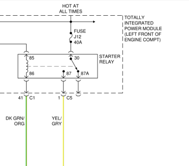
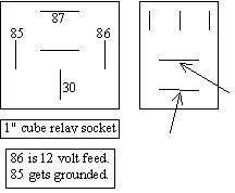
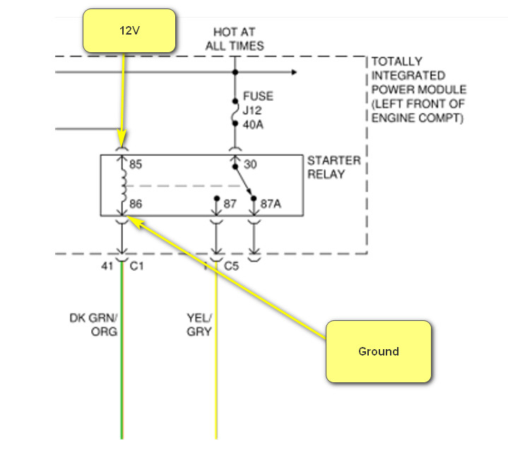
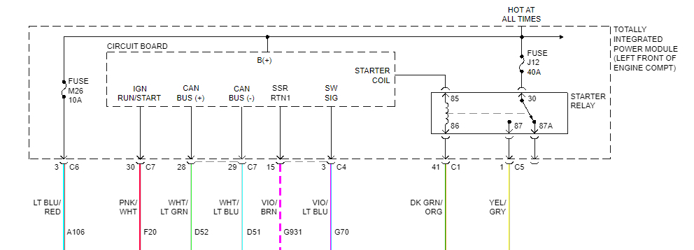
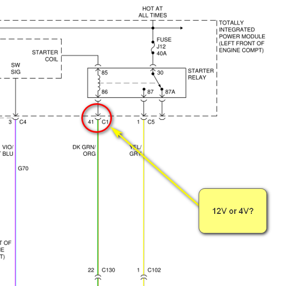
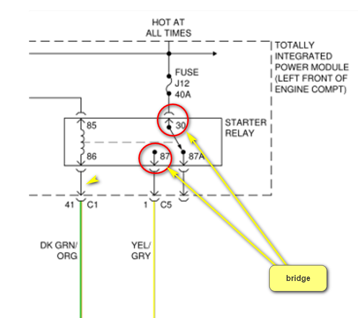
The last diagram is backward. Remember, all relay coils develop a reverse voltage spike when they get turned off, and there's a diode in there to short those spikes out. It is common to not show the diodes as is the case here. Because of that diode, terminals 85 and 86 can't be switched. 12 volts has to come in on terminal 86, and terminal 85 has to get grounded for the relay to energize.

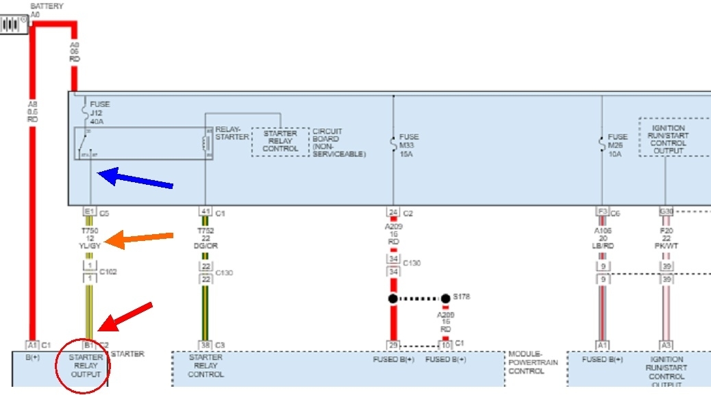
To add to the confusion, we typically draw diagrams to start with the power supplies on top, circuitry in the middle, and grounds at the bottom. Now, with all the computer circuitry, it isn't always practical to do it that way. The 12 volts used to come from the ignition switch. Now it comes from the Engine Computer, (Powertrain Control Module), on the dark green / orange wire. The ground side of the coil is shown at the top in the TIPM. It gets grounded by the "starter relay control" circuitry which takes the place of the neutral safety switch on older models. Once that circuit grounds the relay's coil, the coil is energized. Until that happens, you'll see the 12 volts there that came through the coil from the dark green / orange wire.

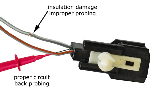
Adding wires to the socket so you can take readings with the relay plugged in is how I do it too. Most voltage readings are only valid when the circuit is "complete", meaning intact and current can flow through it. There are plenty of places where people get "wrapped around the axle" and go down the wrong diagnostic path after getting invalid readings from just part of a circuit. One word of warning though. Forcing a fat wire alongside a relay terminal can spread the female terminal in the socket to the point it makes poor or intermittent connection later. This is even more of a problem on GM vehicles. For those, it's better to wrap the wire around the terminal on the relay first, then install the relay that way. Doing it that way puts no wire alongside the terminals so those in the socket can't spread open.

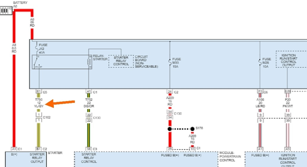
To address your confusion about testing grounds, I added arrows to this diagram. In that ground circuit, ideally there must be no resistance, (0 ohms). In the real world there is always a very tiny amount of resistance in every wire. When current flows through that resistance, it causes some voltage to be "dropped" across it. Most of the time that voltage is too small to measure, and it has no effect on the performance of that circuit. Wire sizes are selected to be as small as possible to save cost, but big enough to not introduce excessive resistance. The voltage dropped is proportional to the current flowing through it, so as current increases, voltage dropped in that wire increases. Unless specified otherwise by the manufacturer, the industry standard is no more than 0.2 volts is allowed to be dropped in that wire.

One of the secrets to this test is the placement of the meter's probes. Wherever you place them, it's between them that is the part of the circuit you're testing. In this diagram, if one probe is placed at the pink arrow, the tiny area below it is not included in the test. That could equate to testing at the end of the ground wire, but not including the screw that attaches it to the body. If under that screw head is where the corrosion / high resistance exists, the voltage drop won't get included in the measurement, so it will be overlooked. For that reason, I like to put one meter probe right on the battery's negative post or cable clamp. If there's a high resistance problem in those other parts of the circuit, it would affect a lot more things with a lot more symptoms. Instead, we can assume those parts are okay, and every high resistance area will be included in the test.

So, if the meter's probe is on the battery's negative post, and the other one is at the blue arrow, the place we'd typically test at, corrosion and the resulting high resistance at the pink arrow will cause a voltage drop when the circuit is energized. That's the other key point I forgot to stress. Current has to be flowing through the resistance for the voltage drop to show up.

Think back to the garden hose. If you start with 50 psi and the nozzle is turned off, you'll have 50 psi all the way up to the nozzle. Now if you stand on the hose and pinch it off 99 percent, you'll still have 50 psi at the nozzle. 0 psi is dropped across the high resistance, (your foot), because no water is trying to flow through that restriction. It isn't until you open the nozzle, (turn on the electrical circuit), that water pressure is dropped across your foot. If 45 psi is dropped across your foot, that leaves just 5 psi to force water to dribble from the opened nozzle. Water flow, (current flow), is reduced to an unusable level by the excessive undesirable resistance.

The next point of confusion is understanding the difference in measuring a voltage "at a point" vs. "Across" something. For this sad example, lets say there's corrosion above the pink arrow that results in a drop of one tenth of a volt. One meter probe is on the battery's negative post. With the other probe, measure at the blue arrow and find 12.0 volts. Next, measure at the pink arrow and find 11.9 volts. Calculating shows there's that 0.1 volt loss. The problem is the meter has a tolerance or accuracy issue where it can be off just a fuzz. With two measurements you have two fuzzes, so in reality you likely have slightly more or less than the 0.1 you calculated. The measurements are taken at two different times a few seconds apart when the battery is slowly running down, or things are turning on or off causing the amount of current to be different between the times the two readings were taken. All of these variables are eliminated when just one reading is taken with one probe at the blue arrow and the other at the pink arrow. Even if current changes or the battery is running down, the variables are eliminated. Just the one reading will show the true voltage drop. 0.1 volts is within the limit and is acceptable.

In the first tests, we took two voltage readings at two points in the circuit, then calculated the voltage drop. At the end, we took just one direct reading across the voltage drop. I should point out too these tests are done to locate areas of undesirable high resistance. Almost all digital meters also measure "Ohms", meaning resistance, directly. The problem is the resistance values can be way too low to measure accurately. It's much more accurate to use these voltage measurements to measure the results of that resistance. Typical meters can measure to the tenth of an ohm, but there can easily be five or more ohms of resistance just in the meter leads themselves. By contrast, a starter motor circuit can be rendered inoperative with as little as a few hundredths of an ohm resistance in the cables. That's way too small to measure, but we can measure the resulting voltage drop. It's with voltage drop tests we always troubleshoot those high-current circuits.

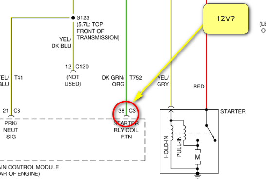
That entire story refers to ground circuits for items such as computer modules, relays, motors, and light bulbs. We want to always see as close to 0.00 volts as possible. Now, we finally get to a different version of grounds. Think back to where you found 4.41 volts on both sides of the relay's coil. We expect to see 12 volts on one side, give or take, and we expect to see 0 volts on the other side, give or take. Relays are pretty forgiving when it comes to that voltage it takes to flip the movable contact. Eight volts is often enough. That means we could have a good three or four volts dropped across undesirable resistances in the circuit and it would still function normally. On older Chrysler products a wire ran from what equates to terminal 85 down to the transmission and its neutral safety switch. The wire, switch, and connector terminals could have a total of a few ohms of resistance, but it wouldn't be enough to prevent the circuit from working. Now the job of the neutral safety switch is being done by the "starter relay control" circuit inside the TIPM, shown at the top of the starter diagram. I can tell you from recent experience that circuit consists of only a relay turned on and off by another computer module. However, a real lot of similar relays on other computers are turned on by their own computer circuits. Those circuits are electrically incapable of drawing the ground side all the way down to 0.00 volts. Most of the time we can't get in there to take measurements, but when we can, it's not uncommon to find well over that magic 0.2 volts. We could even find more than a volt under normal operation. One volt is totally unacceptable in ground wires discussed earlier, but in this case when we talk about ground circuits, we're only interested in whether it's the ground side or the supply side. The exact voltages are of little importance.

That brings me to my last point, finally. That's where you found the 4.41 volts on both sides of the relay's coil. I have a suspicion you found voltages you weren't meant to measure or even know about as they don't help with any diagnostics, and as you've seen, they lead to more confusion. Better to call voltages that low "0 volts" unless you know to expect something else. I think a computer is putting those voltages there, then watching to see if 12 volts shows up from somewhere else, or if one gets shorted to, or "pulled" to ground, meaning near 0 volts. This is better discussed in relation to sensors as it's easier to explain and see. I have diagrams to go further into this if you want me to. To simplify it for now, the computer applies a test voltage to a point, the relay's terminal(s), in this case, through a very large "pull-up" resistor. The resistor is so large electrically that it has almost no effect on the circuit, and it is completely overpowered by the 12 volts and ground when they're present. These pull-up, or test values only show up in a circuit that is not energized or one that has a defect. In this example, he computer knows when it should see 12 volts on one relay terminal and 0 volts on another one, but if it finds 4.41 volts instead, it uses that information to figure out what type of problem is preventing that circuit from working properly. That's how it comes up with such descriptive and helpful diagnostic fault codes. If I'm right, you should find 4.41 volts on terminals 85 and / or 86 with the relay out of the socket.

While much less common, those 4.41 volts could also be "floating" voltages that show up due to all the other interconnected circuitry. We can't actually do any work with those voltages, and of course they do add to the confusion, but proof would be to find the normal 12 volts and near 0 volts when the circuit is activated. Floating voltages are a bigger problem in sensor circuits. When there's a break in the signal wire, you'll still find the correct signal voltage right at the sensor, but not at the computer. The voltage at the computer will "float" to some random value from the other interconnected internal circuitry. If that random voltage falls within the acceptable range for that sensor, the computer will accept it and try to run the engine or circuit on that, but it won't run right. They add the pull-up resistor to prevent that. Once the defect occurs, the pull-up resistor takes over and places, in the case of sensors, five volts on the signal terminal inside the computer. The acceptable range is from 0.5 to 4.5 volts. Five volts is outside that range, so the defect gets detected. This is where you have a fault code describing what's wrong with the signal voltage, you verify that by observing the signal voltage on a scanner, but you think you're going to double-verify that with a measurement right at the sensor and you find the correct, or different voltage there. The cause is a simple broken wire, but this has led to a real lot of confusion even among very experienced mechanics.
Was this
answer
helpful?
Yes
No
Friday, June 3rd, 2022 AT 2:07 PM
Tiny
HAGMAN
  • MEMBER
  • 23 POSTS
Hello,

I agree with everything you stated, and my testing methods are similar to yours. I know that if I'm checking voltage on a ground, it doesn't matter if it's a chassis, body, engine, tied in sensors grounds, ect, if I measure anything over 0.2V then Houston, there is a problem. You had mentioned that the P0750 code should not cause a "no start", so I'm not going to focus on the TSS or gear shift cable. As you stated, I believe something very simple like a bad wire/connection is causing this. Did you say that the PCM grounds the starter relay? Would you happen to have a diagram that shows where the wires connect into the PCM harnesses (C1-C4)? Should I first figure out where that ground wire goes and ends to ohm it out for integrity purposes. What should I be focusing on and testing? Thanks much- you have a good evening depending on what part of the country you're in.
Was this
answer
helpful?
Yes
No
Friday, June 3rd, 2022 AT 5:37 PM
Tiny
CARADIODOC
  • MECHANIC
  • 33,752 POSTS
The transmission fault code only concerns me in the respect the computer may not be able to figure out if the transmission is in "park" or "reverse". That, as with the older neutral safety switch, would inhibit the starter system.

Testing the resistance of wires is usually a time-wasting test except to verify other tests that point to that. All it takes is one strand of the wire still intact to get a perfect reading of near 0 ohms, but that one strand can't pass enough current for the circuit to work. This is where the voltage drop tests would show a very high voltage, pointing to that wire while you wouldn't find it with ohm meter readings. The ohm meter readings are really only effective when locating a wire that has a solid break in it.

Now I'm going to try to confuse you even more by trying to relate this to the 2015 I was helping with a couple of months ago, then I'll finish up with the plugs you asked about. Remember I found the TIPM's name changed, but they were all listed as being the same from 2010 through 2022, so the operation should be similar too. In that system, the "transmission range sensor" takes the place of the neutral safety switch, and is an input to the Engine Computer. When the Engine Computer sees the transmission is in "park", and the ignition switch is in "run" or "crank", it puts 12 volts out on the dark green / orange wire to the starter relay in the TIPM. Next, the "starter relay control" is just a tiny relay inside the TIPM that turns on when the ignition switch is turned to "crank". That grounds terminal 85 of the starter relay. With 12 volts and ground, the starter relay energizes to send 12 volts down to the starter solenoid. The ignition switch and the starter relay control, (neutral safety switch), have changed places compared to the older systems. That might adjust your thinking as you work through this.

Here's the plugs. I forgot to copy their numbers with the line drawings. They're in order, connectors C1 through C7, and C9. There is no plug C8.
Was this
answer
helpful?
Yes
No
Friday, June 3rd, 2022 AT 9:05 PM
Tiny
HAGMAN
  • MEMBER
  • 23 POSTS
Randy-
Thanks for the connector diagrams. Im an expert at camouflage and M60 machine guns, but this is new to me. Im looking at the first image (green arrow) and I should probably test pin 41 to see if power is getting to the relay, which I assume is, since pin 30 reads almost 12 volts. The second image (red arrow) pin 24 should be battery power because it says "Fused B+", but Im not sure what it powers. The fifth image (orange arrow) pin 1 says "starter relay output", so this is probably a signal to the PCM? Dont know? The sixth image (red arrow) pin 3 says "Fused B+", telling me it is power, but Im not sure for what? All of these connectors tell me that they are used for power, input, output or signals. Yeah, you confused me with all this, but its a learning curve. Shit, and their are a lot of them that are specifically for the ignition and Fused B+? Do you think I should start with pin 41 (Starter Relay Control) on the first image connector at the green arrow? What would be your test method of this?
Another thing that I know is that if someone tells me that if they just ohm out a wire and if it has less than 5 ohms, they think the wire is good. For most instances, it is- however, a short to ground or other short can at times show good ohms/resistance, so I try to tell folks, its not a guarantee.
Was this
answer
helpful?
Yes
No
Saturday, June 4th, 2022 AT 8:46 AM
Tiny
CARADIODOC
  • MECHANIC
  • 33,752 POSTS
You're being confused by something that confused me for a long time after Chrysler retired the old geezers who knew how to draw diagrams and hired the over-educated college idiots to take their places. All the rest of us see the term, "output" and know it's a signal or voltage going "out" to something else. Chrysler lists the something else as GETTING the output from whatever it came from. Once you understand this, the diagrams become somewhat easier to follow. Here's a perfect example.

When the starter relay activates, it switches 12 volts onto the "starter relay output" terminal, (blue arrow). All of us normal people call that the output terminal from the TIPM, but here that designation is placed inside the starter motor where we would normally label it as an "input", (red circle and arrow).

Terminal 41 gets 12 volts switched onto it when the starter relay activates. We know that's not happening because that's why we're here. You can prove the rest of that circuit is okay by removing the relay, then jumping terminals 30 and 87 together with a piece of wire or a stretched-out paper clip. That will cause the starter solenoid to engage. That also tells us we have to look at the other half of the relay and its control circuits.

Terminal 24, "Fused B+, is the circuit that sends 12 volts to one of the three or four supplies to the Engine Computer. That circuit comes through the TIPM because that's where the fuses live. Engine Computers, aka Powertrain Control Module, (PCM), commonly have four 12-volt supplies. One is always live to maintain diagnostic fault codes and fuel trim data in memory when the engine is off. One gets 12 volts through the ignition switch when that switch is turned to "run". That turns the computer on. When the engine is rotating, (cranking or running), sensor signals tell the Engine Computer to turn on the automatic shutdown, (ASD) relay which sends 12 volts to the ignition coils, injectors, and many other places. One of those other places is a third 12-volt input to the PCM itself to verify the ASD relay did indeed turn on. One of those 12-volt inputs, or a fourth one, is the line the voltage regulator looks at to monitor system voltage.

As a point of interest, (you won't be tested on this later), is the designation "12 volt B+". When portable radios first came out, they used three batteries. The "A" battery ran the filaments in the tubes. Those were very low voltage. The "C" battery ran other circuitry. The "B" battery was the high voltage battery that was needed by the tubes to operate. That could have been over a 100-volt battery. Ever since, the B+ has been used to designate a power supply voltage that runs the main circuitry. In tv repair, we typically said, "we need B+ and ground for the circuit to work".

You're right that a wire can test good for continuity but be shorted to ground or something else. It's more common to find, as I mentioned previously, the entire wire except for one or two strands can be corroded away. That's like thinking there's good water flow from your kitchen sink faucet, so the plumbing is good for fighting a forest fire.

As for how I would approach this, that's the same question we had on the 2015 a few months ago. We started with the scanner to view live data. It showed the ignition switch was sending a digital signal to the Radio Frequency Hub". That module was found to be sending a signal to the Body Computer. The Body Computer sent 12 volts to the TIPM to the "starter relay control" circuitry to tell it to ground terminal 85 of the starter relay. From here the chain of events differs on your model. Part of our problem was in understanding all the abbreviations and icons on the scanner. Another part was in not having the factory training on how the system works.

Another part of the problem is in years past, all switching was done by turning voltages on and off. Today, with all the computers, they communicate with digital signals that we can't read. The only way to know which signals are showing up is to add another computer to the vehicle, (that's the scanner), that can take those digital signals and translate them into messages we can read and understand. Without the scanner, there's really no way to know which circuits are working and which ones aren't.

The only other method, which we don't normally support, is to substitute known good modules to see if one solves the problem. That's fine for my friend who always has a dozen smashed Chrysler products in his yard to rebuild, but often those modules are programmed to just that vehicle and won't work in a different one. For the rest of us, substituting parts is the most costly and least efficient way of diagnosing a problem.

Once we figured out as much as we could, it appeared our problem was caused by the TIPM. In fact, we read quite often people solved their problems with a new TIPM. A good used one seems to have solved the very intermittent problem. Those, by the way, do not have to be programmed to the vehicle's ID number.
Was this
answer
helpful?
Yes
No
Saturday, June 4th, 2022 AT 2:19 PM

Please login or register to post a reply.

Sponsored links