No power to starter solenoid

Tiny
HAGMAN
  • MEMBER
  • 23 POSTS
Okay, I've been reading up on stuff for a few months now about this generation 4 Rams and have read numerous issues with TIPM's and electrical gremlins. In fact, many have found that on some, the fuel pump relay is built internally in the TIPM and when it takes a shit, they have to make of buy a bypass fused wiring to make it work? Why would someone design it that way to have the fuel pump fuse inside is completely not user friendly? I hope it's not the TIPM- I would not know how much a refurbished one costs. I think this is one of 3 areas:
1. Ignition Switch or WIN (wireless ignition node)
2. Ground from neutral safety switch/trans shift solenoid
3. Connection between PCM and start relay
I'm not sure how and which to check first. What would happen if I spiced into the relay ground wire and ran a separate wire to a good ground?
Was this
answer
helpful?
Yes
No
Saturday, June 4th, 2022 AT 8:17 PM
Tiny
CARADIODOC
  • MECHANIC
  • 33,752 POSTS
My experience has been a failure shows up in multiple places, and bypassing one of those places won't solve anything. When ours would not crank, bypassing the starter relay would get the starter to crank the engine, but the engine would not start or run. After sitting a few minutes, the starter system worked normally and the engine would run. At the same time, when the engine would not crank with the key, it still would crank and run normally with the remote start on the key fob. Multiple systems were shutting down intermittently.

If you could find the starter relay control circuit inside the TIPM, and ground that terminal on the relay, the computer is going to see that 0 volts there when it shouldn't be. Knowing there's a defect, it will shut down or disable some circuits.

All three things you listed can be seen on the scanner. You can watch the items change state as you turn various switches on and off or shift gears. There's really no other way to know what's working and what isn't.
Was this
answer
helpful?
Yes
No
Saturday, June 4th, 2022 AT 11:06 PM
Tiny
HAGMAN
  • MEMBER
  • 23 POSTS
I have a cheap Autel Maxisys scanner that is not too bad. When I view "live data" on it, what parameters should I be looking at on the scanner in "live mode"? I've already verified that the starter relay is receiving power at pin socket 30 which is supposed to happen. I've also verified that the ignition switch- (wireless ignition node) has power getting to it. When the key is held in the start/run position, the ignition switch should send battery voltage to relay terminal pin 86. Since I'm only getting 4.11 volts to pin 86 when key is in start/run, this is nowhere close to battery voltage and points in the direction of the ignition switch itself and/or the wiring from ignition switch to pin 86. With regards to most iso relays, this is the sequence-
1. Pin 30 is connected to battery voltage at all times.
2. Normally open terminal (87) is connected to terminal (30) in the energized position, this supplies battery voltage to the starter solenoid field coils.
3. Terminal (86) is energized when the key is held in start/run position which should have battery voltage, and no voltage when key is released.
4. Ground terminal (85) is grounded through the park/neutral/trs (only) when gear selector is in park or neutral position. Continuity should be present from a good ground to relay cavity 85 (ground terminal). If there is no continuity, most likely there is an open or short to the park/neutral/trs from terminal 85.

As far as the ignition switch- (wireless ignition node):
It is basically a potentiometer which has small contact arms in opposing positions which make contact with the circular contact plates in the circuit board itself. I've already tried to take it apart, but you need to de-solder about 4 points in order to completely remove the circuit board in order to clean the circular contact plates. De-soldring tools is something I do not have but am going to get. I can't see paying $200.00 to $300.00 for a small black box.
Was this
answer
helpful?
Yes
No
Sunday, June 5th, 2022 AT 7:46 AM
Tiny
CARADIODOC
  • MECHANIC
  • 33,752 POSTS
Your four points about the four relay terminals is exactly correct. The problem now is the circuits for terminals 85 and 86 get their power and ground through computerized switching circuitry, and the switches are inputs to those computers. Instead of just a neutral safety switch interrupting the ground circuit, any number of things can be inputs to the computer as it decides whether or not to allow terminal 85 to be grounded. Besides not being in "park", for example, the ground circuit could be interrupted by a door not being closed, the anti-theft system being activated, battery voltage is too low, etc.

Same with the positive side. An aftermarket remote start system might operate, but a factory system won't work if the Check Engine light is on for any reason. That inhibit function might be an input to the "starter relay control" circuit in the Engine Computer. That, along with all the other inputs, must all give the go-ahead for the circuit to work where that had been done with just the ignition switch.

As for what to look for on your scanner, we didn't know what many of the abbreviations stood for. We looked for the things related to starting and watched for those that didn't change state when we turned a switch. For example, "transmission gear". Under "Body Computer", it would list the gear the transmission was in, but not by looking at the transmission range sensor. The scanner was displaying what the Body Computer was seeing, whether that was from a switch or digital data from a different computer. In this case the transmission range sensor takes the place of the neutral safety switch. It's an input to the Transmission Computer. When it's the Transmission Computer's turn to broadcast its data onto the data buss, all the other computers can see it and use it or ignore it. The Body Computer sees that data and picks off the range sensor data, then, when it sees the transmission is in "park", it allows the TIPM to activate the circuitry involved with running the starter relay. All we need is to see on the scanner the final step in that sequence to know everything leading up to that point has to be working. No need to waste time testing the range sensor or its wiring, and things like that.

We spent so many hours on our truck, and developed so much confusion, but it finally came down to everything pointed to the TIPM. That's when we finally broke down and found a good used one to substitute as a test. Being so intermittent, you can never be sure it's solved, but so far the problem hasn't come back.
Was this
answer
helpful?
Yes
No
Sunday, June 5th, 2022 AT 9:48 AM
Tiny
HAGMAN
  • MEMBER
  • 23 POSTS
Your 100% correct when you say about computers controlling everything. I used to have a 1984 Chevy Silverado years ago and had none of that computer junk on it. I understand the need to have good air quality and is the main reason OBD came out in the first place and emissions is still the main mission of OBD2 and soon OBD3. So, the weather was perfect today and I decided to do a couple continuity tests from the small 12 pin connector on back of the wireless ignition node box- Here are the pins identification:

WIRELESS IGNITION NODE

1- Light Blue/Red- Power (From fuse M26)
2- Empty
3- Pink/White- Ign Run/Start Control Output
4- Black/Lt Green- Ground
5- White/Tan- Can C Bus +
6- White/Lt Blue- Can C Bus -
7- Brown/Yellow- BTSI (Brake Trans Shift Interlock) Control
8- White- Brake Lamp Switch Output
9- Empty
10- Empty
11- Empty
12- Yellow/Dk Blue- TRS Park Signal

Well, at Pin 3 (Ign Run/Start control output) was a reading of 5.98Kohms from the node connector to the TIPM connector pin? BIG RED FLAG
Next- Pin 4 (Ground) was reading 20 Ohms from the node connector to the TIPM connector pin? ANOTHER RED FLAG

These wires travel from the back of the ign switch to the TIPM- the problem is what route they take? It looks like all the wires from the back of the switch get routed up and to the right way up in the dash behind the center console and I'm not sure if they come out the right side engine bay or the left side. What I'm trying to say is that it is going to be a cluster if I got to tear apart the whole dash just to try and do a leap frog testing of 2 small 18 gauge wires. Fun, Fun-
Was this
answer
helpful?
Yes
No
Sunday, June 5th, 2022 AT 9:24 PM
Tiny
BORIS K
  • MECHANIC
  • 762 POSTS
Hello

I seem to have confused terminals 85+86.
Terminal 86 is the 12V activation from the PCM, dark/green/orange wire from connector C3 pin 38 at the PCM. The TIPM is switching a ground at terminal 85 when cranking.
The voltage from the PCM at pin 38 is not enough.
I would suggest to check directly at the PCM, pin 38, when cranking/key on if 12V is given there. See image below
If it is then we know that the PCM is outputting the correct voltage.

Next check if 12V is given at the TIPM, connector C1 pin 41. Image 2 below
If 12 v is given at this terminal then this proves that the wire is intact.
If the voltage at the TIPM pin 41 is only 4V then this shows that the wire has a high resistance and needs replacing.

If 12V is given at pin 41 and only 4V given at terminal 86 then this shows that the TIPM is bad

Cheers, Boris
Was this
answer
helpful?
Yes
No
Thursday, June 9th, 2022 AT 7:11 AM
Tiny
HAGMAN
  • MEMBER
  • 23 POSTS
Hello Boris,

Thanks for getting back to me. Today, I took off the PCM C3 connector and did a voltage reading directly to pin 38 with key turned to run/start- No volts? I'm thinking this has something to do with the P0750 code? What are your thoughts?
Was this
answer
helpful?
Yes
No
Thursday, June 9th, 2022 AT 6:16 PM
Tiny
BORIS K
  • MECHANIC
  • 762 POSTS
Hello,

The PCM connector will have to be connected to the PCM as the PCM will not power up. You will need to back probe the connector at pin 38.

I suggest you use a thin metal pin to gain access and then use the voltmeter and check voltage at the pin while cranking.

Do not pierce the wire, back probe into the connector.
See image below.

Hope this helps.

Cheers, Boris
Was this
answer
helpful?
Yes
No
Friday, June 10th, 2022 AT 9:33 AM
Tiny
HAGMAN
  • MEMBER
  • 23 POSTS
Yes, okay. I was not sure. I have some probes I can use. I'll check that 38 wire with the harness connected and get back to you. Thanks
Was this
answer
helpful?
Yes
No
Friday, June 10th, 2022 AT 11:34 AM
Tiny
HAGMAN
  • MEMBER
  • 23 POSTS
Greetings Boris,

Today, I back-probed wire 38 and with key turned to run/start I got.001 volts? So, I started thinking about the P0750 code and took off the PCM C4 connector and started doing ohm on shift solenoids- I forgot which ones, but the first test showed OL. I thought, okay and tested another and got OL and the third one, again OL? I then went underneath and disconnected the TSS harness on side of transmission (very tight space). Took it off and was thinking to hook up the air compressor and try to shoot some air in the pin area of the TSS. I applied air and noticed a few small bits of rock or road debris come flying out. When I went to plug the connector back in, it for some reason was not wanting to go in completely? I pulled the harness side back out and tried again, same resistance, so after the fourth time, I went looking for my inspection mirror and of course, could not find it. Ended up using the wife's small make-up bad mirror and looks like a small plastic piece (which there were a few) that I'm assuming is just a guide to align the pins to the sockets of the harness side was bent? So, I got out from under the truck as other things had to be done around the house. Is it possible that the small plastic piece could have been causing a weak connection? What are your thoughts?
Was this
answer
helpful?
Yes
No
Saturday, June 11th, 2022 AT 10:22 PM
Tiny
BORIS K
  • MECHANIC
  • 762 POSTS
Hello,

I sounds like that the pin you used to back probe the wire at pin 38 did not make proper contact. You had a reading of 4V+ at the starter solenoid terminal 86 before. Have you tried to bridge terminals 30+87 at the starter solenoid socket? With ignition on this should start the motor. Ensure that transmission is in park/neutral before trying this

Code P0750 will not cause a starting issue, it will put the transmission in limp home mode.
Did disconnecting, cleaning and then reconnecting the transmission connector fix P0750?

A good discussion regarding P0750 can be found here:
https://www.ramforumz.com/threads/limp-mode-with-p0750.174265/

Testing for P0750 is done at PCM connector C4(black/green), pin 10, and transmission connector pin 2. Test wire pin to pin for possible open circuit or high resistance, more than 5 ohm.

This DTC is strictly an electrical fault and cannot be caused by any internal transmission failure other than an open in the Transmission Solenoid/TRS Assembly. If the Transmission Solenoid/TRS assembly is in need of replacement †do not replace the Valve Body.

Cheers, Boris
Was this
answer
helpful?
Yes
No
Monday, June 13th, 2022 AT 1:44 AM
Tiny
HAGMAN
  • MEMBER
  • 23 POSTS
Hello Boris,

The weather here has been hit and miss the past few days. When I tested pin 38 at C4 connector, I could not figure out how to disassemble the harness body, so I pierced the wire as close to the PCM as I could and tested it and got the 0 Volts. I did in fact, jump the relay sockets 30 to 87 and the starter did turn, so I know the starter works fine and the yellow/grey starter solenoid wire is good. I have not tried to re-connect the TSS connector back on due to the weather. Since it is still disconnected, before I re-connect, I'll do what you mentioned above and check ohms from C4 pin 10 to TSS pin 2 and see what I get. I will let you know as soon as this is completed. I again appreciate the help and the diagram you sent. Thanks again Boris.
Was this
answer
helpful?
Yes
No
Monday, June 13th, 2022 AT 8:06 AM
Tiny
HAGMAN
  • MEMBER
  • 23 POSTS
I did ohm check from PCM C4 Pin 10 to TSS Pin 2 and got 00.5 Ohms. So, that tells me the wire has integrity.
Was this
answer
helpful?
Yes
No
Monday, June 13th, 2022 AT 9:18 PM
Tiny
BORIS K
  • MECHANIC
  • 762 POSTS
Hello,

Theory of operation to set P0750

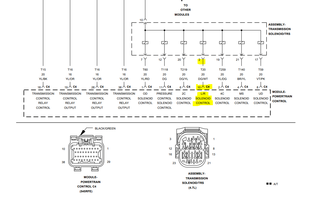
The Transmission Control System uses six electronically controlled solenoids that allow hydraulic fluid to be applied to various friction elements (clutches), which enables the gear requested. The continuity of each solenoid circuit is periodically tested. Each inactive solenoid is turned on for a few milliseconds, then off. Each active solenoid is turned
off for a few milliseconds, then on. This pulsing of voltage to the solenoid causes an inductive spike which can be sensed by the Transmission Control System. If an inductive spike is not sensed by the Transmission Control System during the
continuity check, it is tested again. If the test fails three consecutive times, the appropriate Diagnostic Trouble Code (DTC) is set. If the solenoid test is run in response to a gear ratio or pressure switch error, one failure will result in setting the appropriate DTC.

Possible causes:

Related TCM Power Input DTCs Present.
(T20) L/R Solenoid Control Circuit Shorted to other Circuits.
(T20) L/R Solenoid Control Circuit Open.
(T20) L/R Solenoid Control Circuit Shorted to Ground.
Transmission Solenoid/TRS Assembly.
Powertrain Control Module (PCM).

Next test at the transmission connector would be to check if any of the other pins has continuity (short circuit) to pin 2. Also test the pins for a possible short to ground or positive.
Test pin 2 to pins 12, 17, 19, 20 and 21.
If no short to any other pin can be seen, then you most likely have a failed transmission solenoid pack.

This will still not cause the non-start.

Cheers, Boris
Was this
answer
helpful?
Yes
No
Tuesday, June 14th, 2022 AT 12:38 AM
Tiny
HAGMAN
  • MEMBER
  • 23 POSTS
Thanks Boris, you are a wealth of information. I'm printing out everything and putting it in a folder for future reference. Okay, to understand you correctly, I will be testing continuity from TSS Pin 2 to Pins 12, 17, 19, 20 and 21. We had a bad storm last night and there is nothing but puddles of water under the truck, so I'll have to wait until the ground dries enough to test. I'm hoping between this test and fixing the issue with the small plastic piece, I will know for sure what the issue is and then go from there. Thanks again Boris. Have a good day.
Was this
answer
helpful?
Yes
No
Tuesday, June 14th, 2022 AT 7:31 AM

Please login or register to post a reply.

Sponsored links