Hi,
It sounds like a wiring issue. If you have already replaced both sensors, either there is corrosion at the PCM (power-train control module) or sensor, a damaged connector, a damaged wire, or the PCM itself has failed.
What I am going to provide is a flow chart related specifically to this code. It is a bit involved, but that is the point where you are. Here are the directions and the pictures will correlate with the directions.
____________________________________________
2007 Chrysler Truck PT Cruiser
Gas
Vehicle ALL Diagnostic Trouble Codes ( DTC ) Testing and Inspection P Code Charts P0340 Gas
GAS
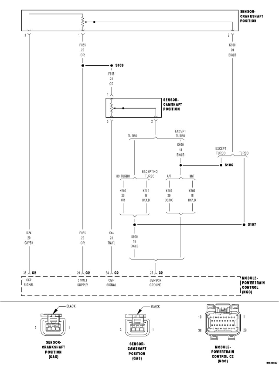
P0340-CAMSHAFT POSITION SENSOR CIRCUIT
pic 1
For a complete wiring diagram refer to Diagrams/Electrical.
- When Monitored:
During engine cranking and with the engine running. Battery voltage greater than 10 volts.
- Set Condition:
At least 5 seconds or 2.5 engine revolutions have elapsed with crankshaft position sensor signals present but no camshaft position sensor signal. One Trip Fault. Three good trips to turn off the MIL.
pic 2
Always perform the Pre-Diagnostic Troubleshooting procedure before proceeding.
Diagnostic Test
1. ACTIVE DTC
Crank the engine.
Ignition on, engine not running.
With a scan tool read the DTCs.
Is the DTC active at this time?
Yes
- Go To 2
No
- Go To 14
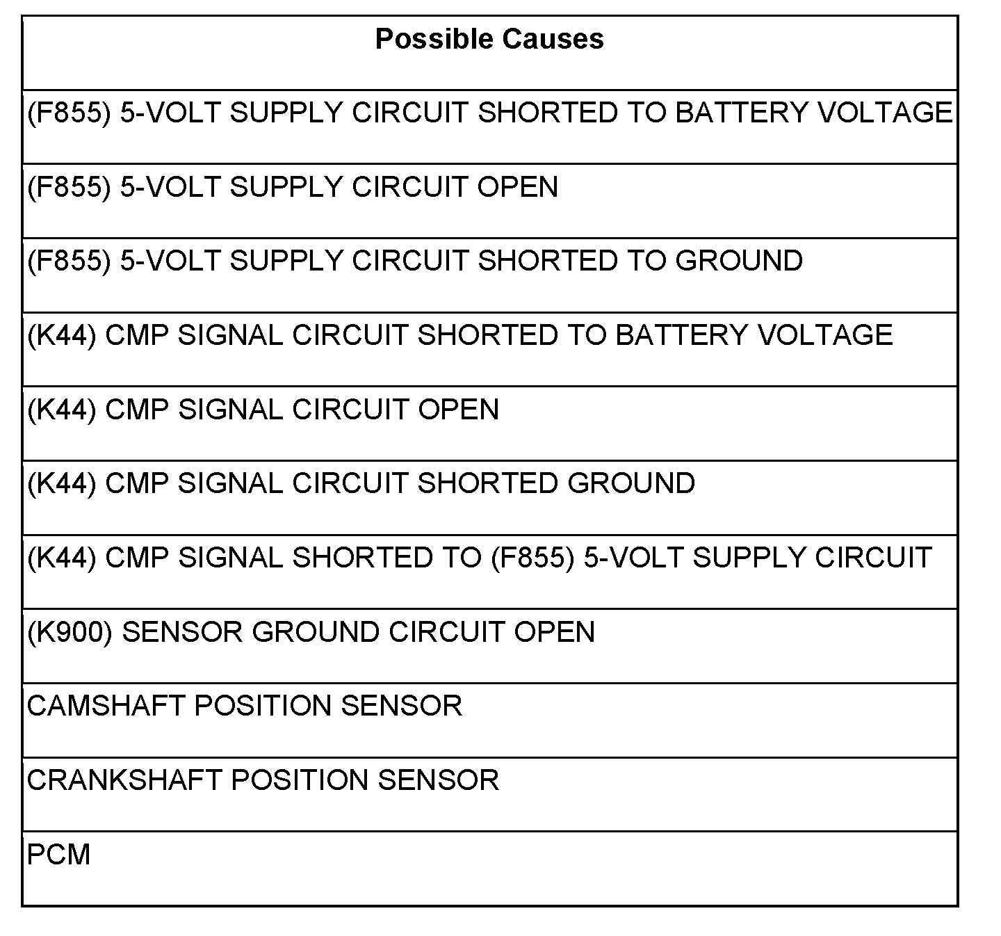
2. (F855) 5-VOLT SUPPLY CIRCUIT
pic 3
Turn the ignition off.
Disconnect the CMP Sensor harness connector.
Ignition on, engine not running.
Measure the voltage on the (F855) 5-volt Supply circuit in the CMP Sensor harness connector.
Is the voltage between 4.5 and 5.2 volts?
Yes
- Go To 3
No
- Go To 10
3. (K44) CMP SIGNAL CIRCUIT
pic 4
Measure the voltage on the (K44) CMP Signal circuit in the CMP Sensor harness connector.
Is the voltage between 4.5 and 5.0 volts?
Yes
- Go To 4
No
- Go To 7
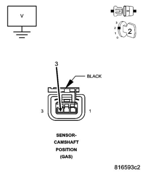
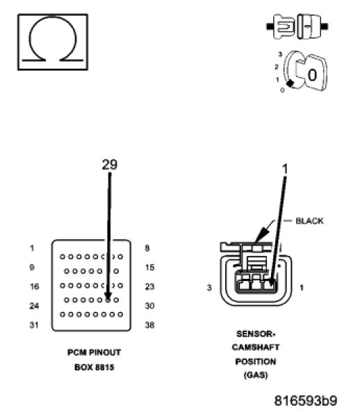
4. (K900) SENSOR GROUND CIRCUIT OPEN
pic 5
Turn the ignition off.
Disconnect the PCM harness connectors.
CAUTION: Do not probe the PCM harness connectors. Probing the PCM harness connectors will damage the PCM terminals resulting in poor terminal to pin connection. Install Miller Special Tool #8815 to perform diagnosis.
Measure the resistance of the (K900) Sensor ground circuit from the CMP Sensor harness connector to the appropriate terminal of special tool #8815.
Is the resistance below 5.0 ohms?
Yes
- Go To 5
No
- Repair the open in the (K900) Sensor ground circuit.
- Perform the POWERTRAIN VERIFICATION TEST. See: A L L Diagnostic Trouble Codes ( DTC ) > Verification Tests > Powertrain Verification Test
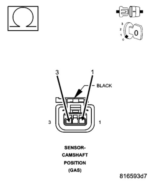
5. (K44) CMP SIGNAL SHORTED TO THE (F855) 5-VOLT SUPPLY CIRCUIT
pic 6
Measure the resistance between the (K44) CMP Signal circuit and the (F855) 5-volt Supply circuit in the CMP Sensor harness connector.
Is the resistance below 5.0 ohms?
Yes
- Repair the short between the (K44) CMP Signal circuit and the (F855) 5-volt Supply circuit.
- Perform the POWERTRAIN VERIFICATION TEST. See: A L L Diagnostic Trouble Codes ( DTC ) > Verification Tests > Powertrain Verification Test
No
- Go To 6
6. CAMSHAFT POSITION SENSOR
NOTE: Inspect the Camshaft sprocket for damage. If a problem is found repair as necessary.
If there are no possible causes remaining, view repair.
Repair
- Replace the Camshaft Position Sensor.
- Perform the POWERTRAIN VERIFICATION TEST. See: A L L Diagnostic Trouble Codes ( DTC ) > Verification Tests > Powertrain Verification Test
7. (K44) CMP SIGNAL CIRCUIT SHORTED TO BATTERY VOLTAGE
pic 7
Turn the ignition off.
Disconnect the PCM harness connectors.
Ignition on, engine not running.
Measure the voltage on the (K44) CMP Signal circuit in the CMP Sensor harness connector.
Is the voltage above 0 volts?
Yes
- Repair the short to battery voltage in the (K44) CMP Signal circuit.
- Perform the POWERTRAIN VERIFICATION TEST. See: A L L Diagnostic Trouble Codes ( DTC ) > Verification Tests > Powertrain Verification Test
No
- Go To 8
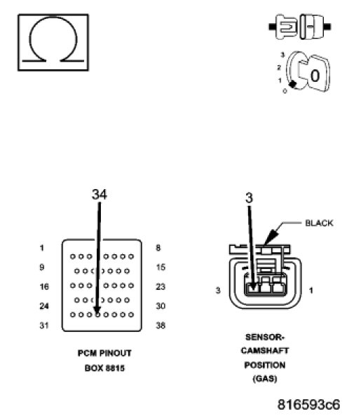
8. (K44) CMP SIGNAL CIRCUIT OPEN
pic 8
Turn the ignition off.
CAUTION: Do not probe the PCM harness connectors. Probing the PCM harness connectors will damage the PCM terminals resulting in poor terminal to pin connection. Install Miller Special Tool #8815 to perform diagnosis.
Measure the resistance of the (K44) CMP Signal circuit from the CMP Sensor harness connector to the appropriate terminal of special tool #8815.
Is the resistance below 5.0 ohms?
Yes
- Go To 9
No
- Repair the open in the (K44) CMP Signal circuit.
- Perform the POWERTRAIN VERIFICATION TEST. See: A L L Diagnostic Trouble Codes ( DTC ) > Verification Tests > Powertrain Verification Test
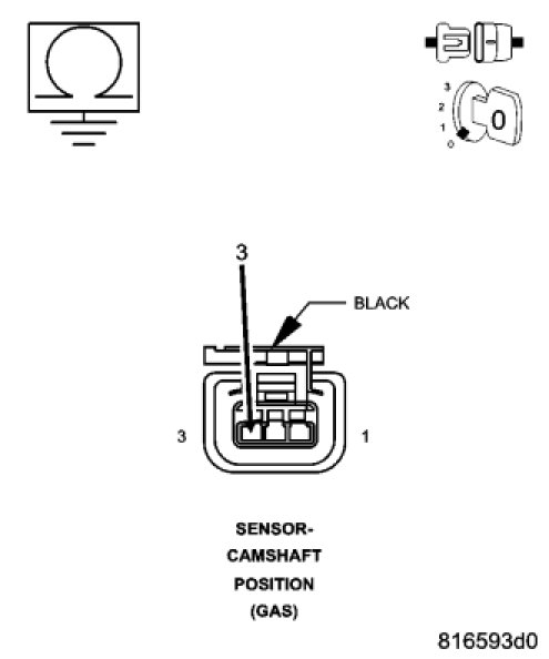
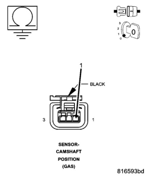
9. (K44) CMP SIGNAL CIRCUIT SHORTED TO GROUND
pic 9
Measure the resistance between ground and the (K44) CMP Signal circuit in the CMP Sensor harness connector.
Is the resistance below 100 ohms?
Yes
- Repair the short to ground in the (K44) CMP Signal circuit
- Perform the POWERTRAIN VERIFICATION TEST. See: A L L Diagnostic Trouble Codes ( DTC ) > Verification Tests > Powertrain Verification Test
No
- Go To 10
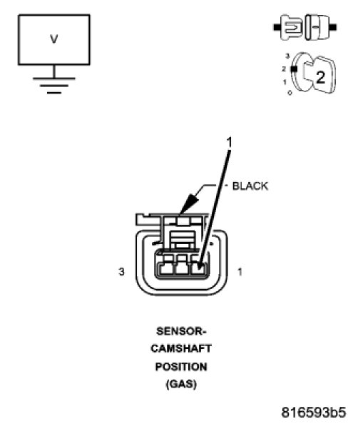
10. (F855) 5-VOLT SUPPLY CIRCUIT SHORTED TO BATTERY VOLTAGE
pic 10
Turn the ignition off.
Disconnect the PCM harness connectors.
Ignition on, engine not running.
Measure the voltage on the (F855) 5-volt Supply circuit in the CMP Sensor harness connector.
Is the voltage above 0 volts?
Yes
- Repair the short to battery voltage in the (F855) 5-volt Supply circuit.
- Perform the POWERTRAIN VERIFICATION TEST. See: A L L Diagnostic Trouble Codes ( DTC ) > Verification Tests > Powertrain Verification Test
No
- Go To 11
11. (F855) 5-VOLT SUPPLY CIRCUIT OPEN
pic 11
Turn the ignition off.
CAUTION: Do not probe the PCM harness connectors. Probing the PCM harness connectors will damage the PCM terminals resulting in poor terminal to pin connection. Install Miller Special Tool #8815 to perform diagnosis.
Measure the resistance of the (F855) 5-volt Supply circuit between the CMP Sensor harness connector to the appropriate terminal of special tool #8815.
Is the resistance below 5.0 ohms?
Yes
- Go To 12
No
- Repair the open in the (F855) 5-volt Supply circuit.
- Perform the POWERTRAIN VERIFICATION TEST. See: A L L Diagnostic Trouble Codes ( DTC ) > Verification Tests > Powertrain Verification Test
12. (F855) 5-VOLT SUPPLY CIRCUIT SHORTED TO GROUND
pic 12
Measure the resistance between ground and the (F855) 5-volt Supply circuit in the CMP Sensor harness connector.
Is the resistance below 100 ohms?
Yes
- Repair the short to ground in the (F855) 5-volt Supply circuit.
- Perform the POWERTRAIN VERIFICATION TEST. See: A L L Diagnostic Trouble Codes ( DTC ) > Verification Tests > Powertrain Verification Test
No
- Go To 13
13. PCM
NOTE: Before continuing, check the PCM harness connector terminals for corrosion, damage, or terminal push out. Repair as necessary.
Using the schematics as a guide, inspect the wire harness and connectors. Pay particular attention to all Power and Ground circuits.
Were there any problems found?
Yes
- Repair as necessary.
- Perform the POWERTRAIN VERIFICATION TEST. See: A L L Diagnostic Trouble Codes ( DTC ) > Verification Tests > Powertrain Verification Test
No
- Replace and program the Powertrain Control Module.
- Perform the POWERTRAIN VERIFICATION TEST. See: A L L Diagnostic Trouble Codes ( DTC ) > Verification Tests > Powertrain Verification Test
14. ERRATIC CMP SIGNAL
With a lab scope probe and the Miller special tool #6801, back probe the (K44) CMP Signal circuit in the CMP harness connector.
WARNING: When the engine is operating, do not stand in direct line with the fan. Do not put your hands near the pulleys, belts, or fan. Do not wear loose clothing. Failure to follow these instructions can result in personal injury or death.
Ignition on, engine not running.
Wiggle the related wire harness and lightly tap the Camshaft Position Sensor.
Observe the lab scope screen.
Allow the engine to idle.
Observe the lab scope screen.
Did the CMP Sensor generate any erratic pulses?
Yes
- Replace the Camshaft Position Sensor.
- Perform the POWERTRAIN VERIFICATION TEST. See: A L L Diagnostic Trouble Codes ( DTC ) > Verification Tests > Powertrain Verification Test
No
- Go To 15
15. ERRATIC CKP SIGNAL
Turn the ignition off.
With a lab scope probe and the Miller special tool #6801, backprobe the (K24) CKP Signal circuit in the CKP harness connector.
WARNING: When the engine is operating, do not stand in direct line with the fan. Do not put your hands near the pulleys, belts, or fan. Do not wear loose clothing. Failure to follow these instructions can result in personal injury or death.
Ignition on, engine not running.
Wiggle the related wire harness and lightly tap on the Crankshaft Position Sensor.
Observe the lab scope screen.
Allow the engine to idle.
Observe the lab scope screen.
Did the CKP Sensor generate any erratic pulses?
Yes
- Replace the Crankshaft Position Sensor.
- Perform the POWERTRAIN VERIFICATION TEST. See: A L L Diagnostic Trouble Codes ( DTC ) > Verification Tests > Powertrain Verification Test
No
- Test Complete.
__________________________________________
I have to be honest. Most times it is corrosion at the PCM connector. If you plan to disconnect and check it, make sure the battery is disconnected first. Also, reattach the connector at the PCM before connecting the battery.
Here are a few links you may find helpful.
https://www.2carpros.com/articles/how-to-use-a-test-light-circuit-tester
https://www.2carpros.com/articles/how-to-use-a-voltmeter
https://www.2carpros.com/articles/how-to-check-wiring
Let me know if this helps or if you have other questions. Also, let me know if you are getting spark to the plugs.
https://www.2carpros.com/articles/how-to-test-an-ignition-system
Take care,
Joe
Images (Click to make bigger)
Friday, April 3rd, 2020 AT 5:24 PM