Will not start, ECM/TCM/PCM codes?

Tiny
BOSSEMNES915
  • MEMBER
  • 2010 FORD FUSION
  • 2.5L
  • 4 CYL
  • 2WD
  • AUTOMATIC
  • 180,000 MILES
I just bought the car, it won’t start, there’s no spark, and it keeps throwing ECM/TCM/and PCM codes. I need the wiring diagrams for the PCM and fuse box connectors/pins so I can test all of them.
Friday, May 5th, 2023 AT 8:02 PM

37 Replies

Tiny
KEN L
  • MASTER CERTIFIED MECHANIC
  • 43,332 POSTS
Sure, can I ask what the codes are? Here is a guide to help you check the connections and the engine and PCM wiring diagrams in the images below:

https://www.2carpros.com/articles/how-to-check-wiring

Check out the images (below). Let us know what happens and please upload pictures or videos of the problem so we can see what's going on.
Was this
answer
helpful?
Yes
No
Saturday, May 6th, 2023 AT 11:53 AM
Tiny
BOSSEMNES915
  • MEMBER
  • 21 POSTS
This is a screenshot of all of the codes that show up.
Was this
answer
helpful?
Yes
No
Saturday, May 6th, 2023 AT 6:53 PM
Tiny
KEN L
  • MASTER CERTIFIED MECHANIC
  • 43,332 POSTS
Yep, those are some codes all right, please clear them and then without trying to start the engine turn the system on and run the codes again let me know what comes up.
Was this
answer
helpful?
Yes
No
Sunday, May 7th, 2023 AT 11:25 AM
Tiny
BOSSEMNES915
  • MEMBER
  • 21 POSTS
The codes are the same.
Was this
answer
helpful?
Yes
No
Sunday, May 7th, 2023 AT 3:21 PM
Tiny
KEN L
  • MASTER CERTIFIED MECHANIC
  • 43,332 POSTS
Start by checking all fuses with the system on.

Here is a guide that should help:

https://www.2carpros.com/articles/how-to-check-a-car-fuse

I would do a CAN scan which goes over the entire car.

you can get a CAN scanner (Controller Area Network) which will work on most cars from Amazon.

Here is a video to show you how:

https://youtu.be/u-4syLc-ifQ

and

https://www.2carpros.com/articles/can-scan-controller-area-network-easy

If all the fuses are good, it sounds like the BCM is out. Please let us know what happens.
Was this
answer
helpful?
Yes
No
Monday, May 8th, 2023 AT 1:29 PM
Tiny
BOSSEMNES915
  • MEMBER
  • 21 POSTS
There were no codes when I scanned it with a can scanner. After watching some videos I think it’s the CKP sensor or wiring but I can’t find a pin out diagram to test it.
Was this
answer
helpful?
Yes
No
Monday, May 15th, 2023 AT 4:12 PM
Tiny
BOSSEMNES915
  • MEMBER
  • 21 POSTS
I also don’t know which of the three connectors I should be looking at.
Was this
answer
helpful?
Yes
No
Monday, May 15th, 2023 AT 4:15 PM
Tiny
AL514
  • MECHANIC
  • 4,146 POSTS
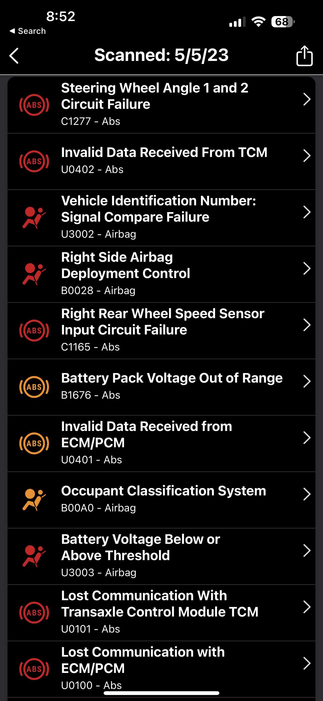
Hello, did any of those codes come back? I see a lot of communication codes.
And is this a Hybrid? Seeing that there are some voltage codes, low voltage can cause communication errors especially on networks that are 12volt pull down type circuits. Canbus is only up to 5volt with a 2.5volt bias on the circuit, but some other networks can be 12volt type.
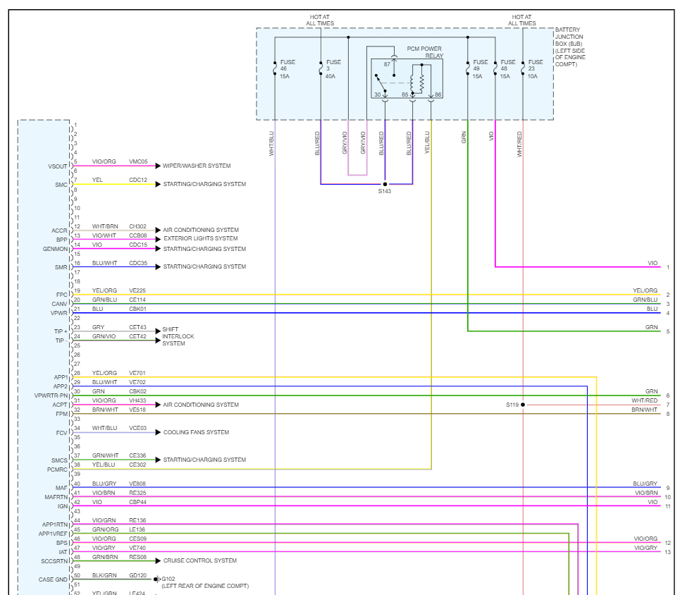
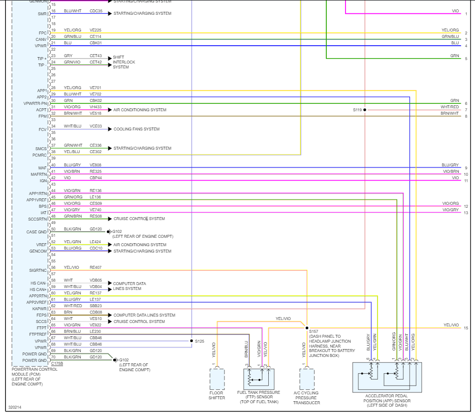
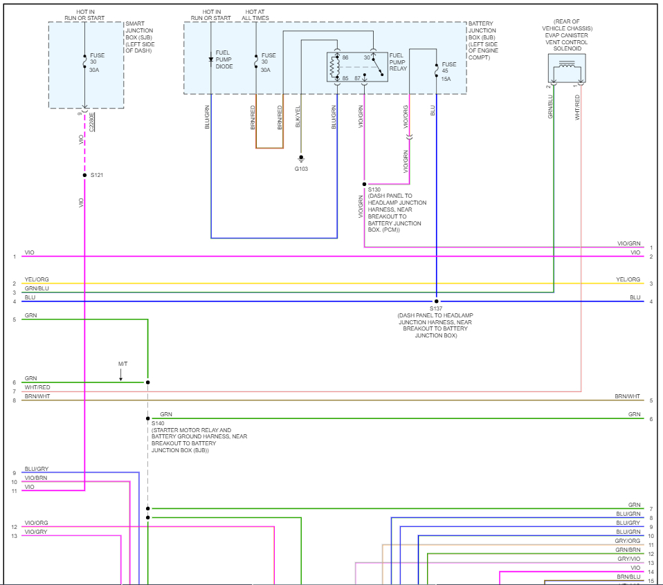
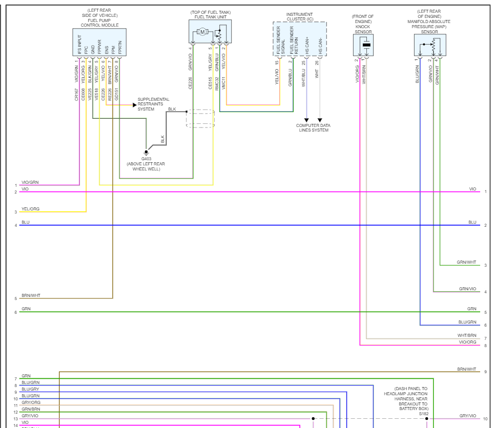
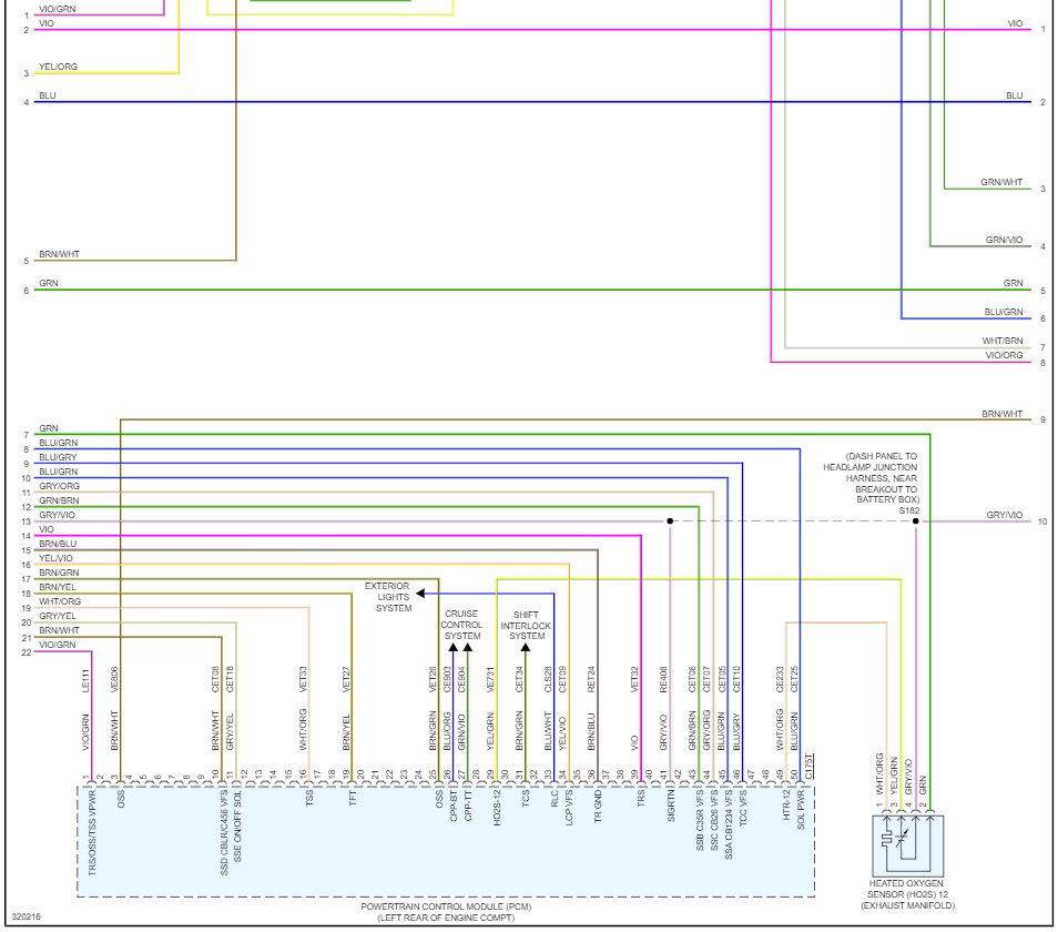
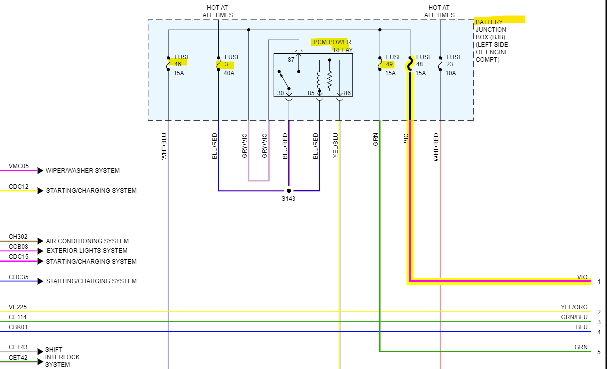
If this is not a Hybrid, we can pull up the ECM diagrams and check powers and grounds. If you turn the key to the on position, engine off the Check engine light should come on, if it doesn't the ECM is not being powered up,
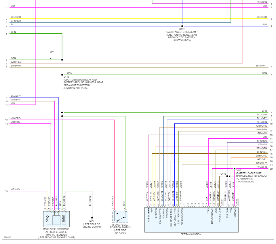
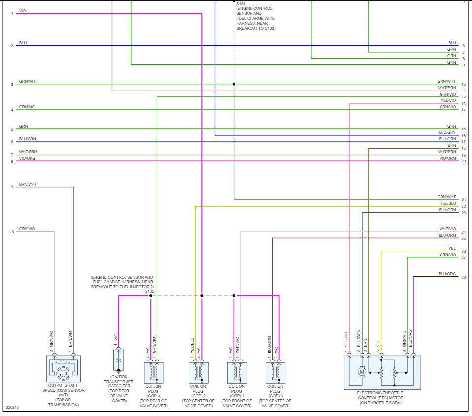
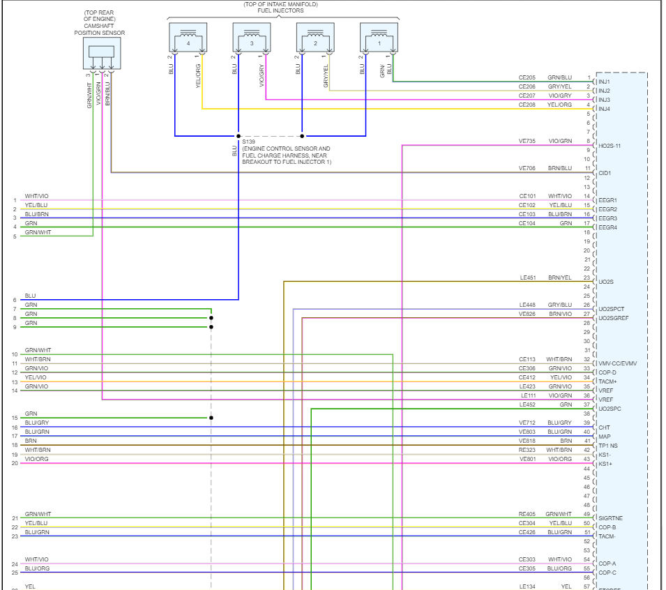
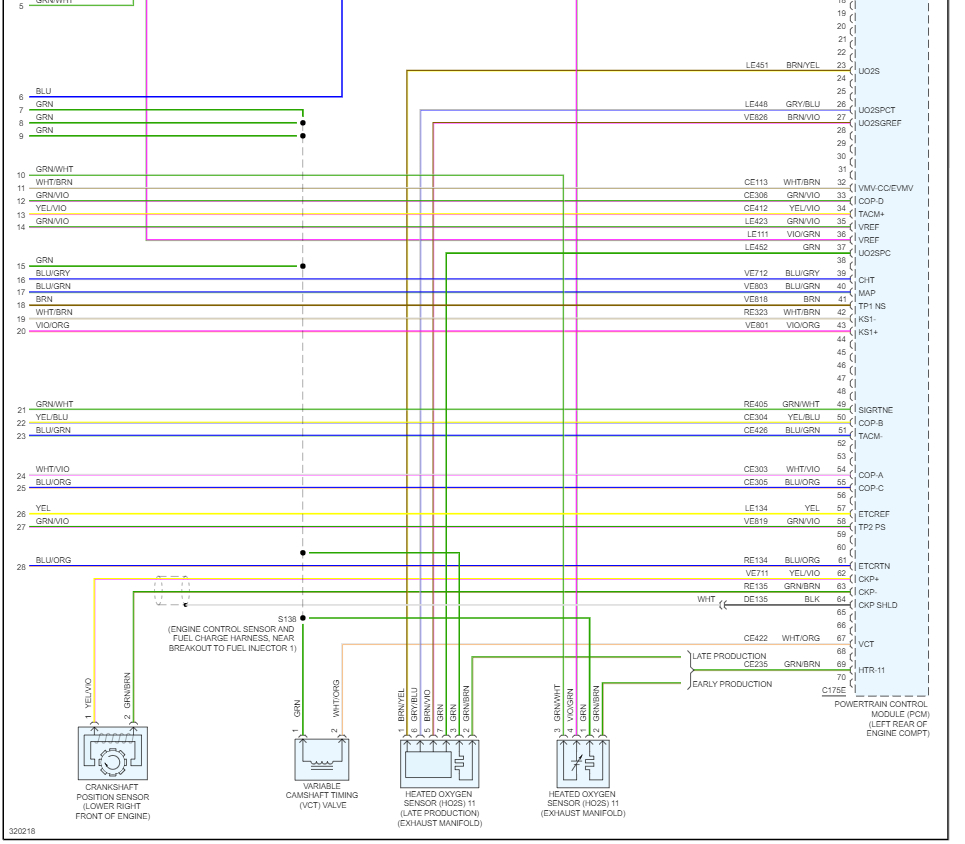
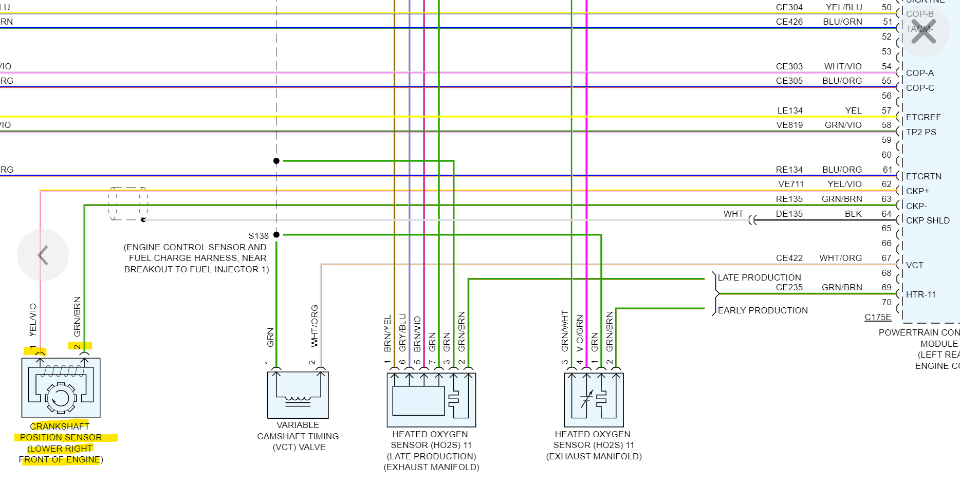
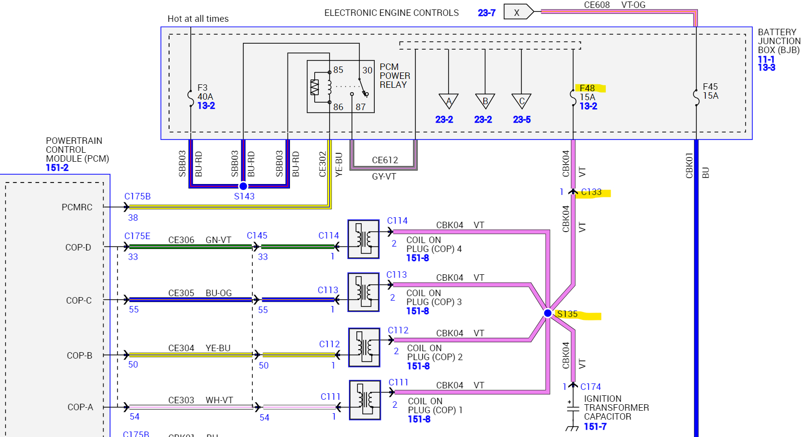
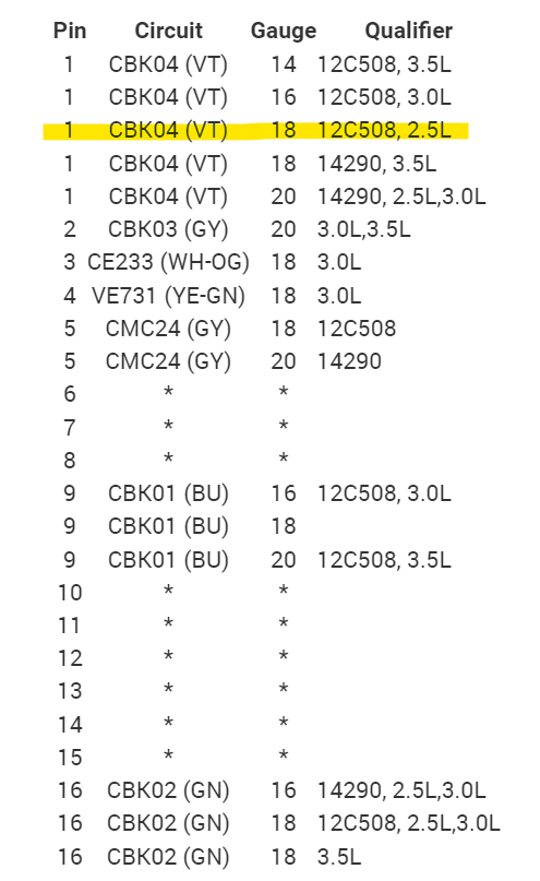
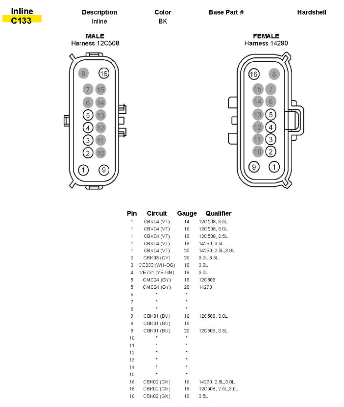
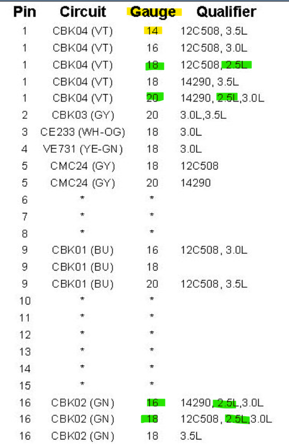
Here is the crank position sensor, it's a 2-wire sensor, a variable reluctance sensor that produces a sinewave signal to the ECM,
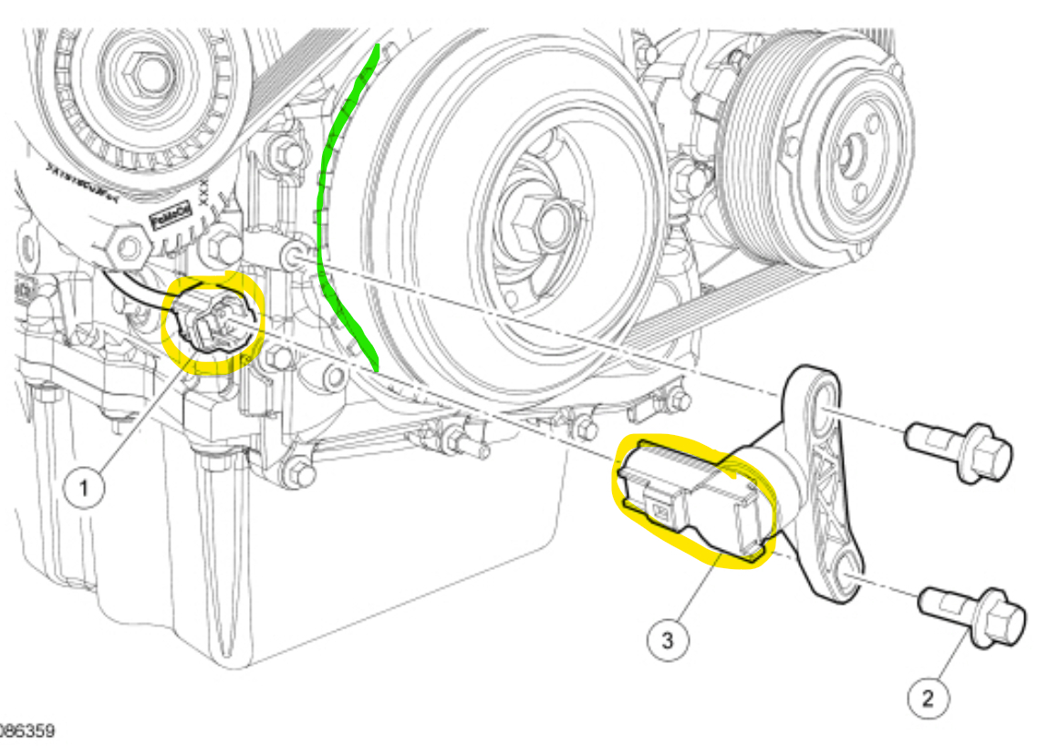
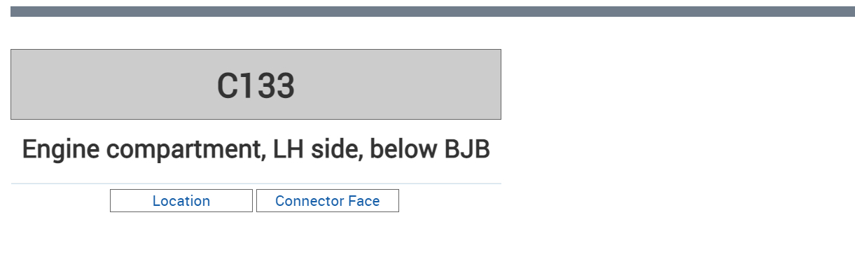
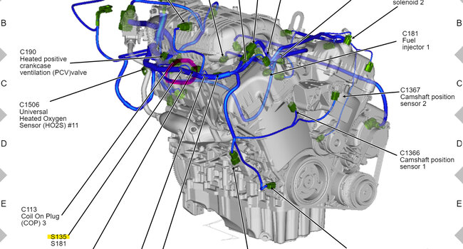
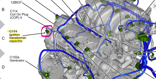
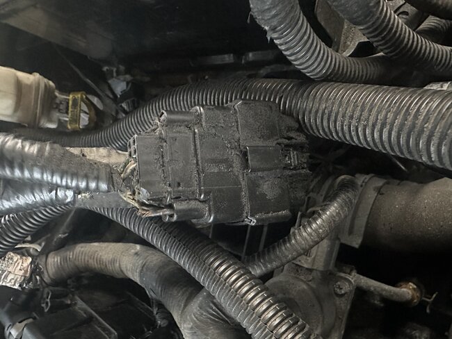
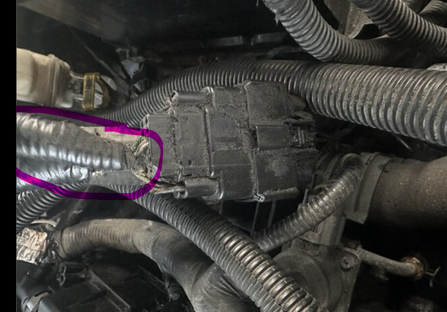
Here is its location, the green is the trigger wheel for the sensor, verify the wiring is good to it.
But I would verify power and ground to everything else first, there is quite the process for replacing the crank position sensor and then a crank relearn procedure as well.
Was this
answer
helpful?
Yes
No
Monday, May 15th, 2023 AT 4:51 PM
Tiny
BOSSEMNES915
  • MEMBER
  • 21 POSTS
It’s the SE and how would I check all of the power and grounds. Also, I don’t know if I did it wrong or not but I back probed the wires for the CKP with my multimeter set to ohms and it kept reading 1.
Was this
answer
helpful?
Yes
No
Monday, May 15th, 2023 AT 7:10 PM
Tiny
BOSSEMNES915
  • MEMBER
  • 21 POSTS
I was thinking about back probing new wires from the PCM to the CKP just to see if the wires are the problem but I don’t know what wire I need. And I tried reading the resistance for the CKP from different connectors and it always read the same thing.
Was this
answer
helpful?
Yes
No
Monday, May 15th, 2023 AT 7:15 PM
Tiny
AL514
  • MECHANIC
  • 4,146 POSTS
The resistance of the crank position sensor is going to be between 0.25k to 1.1k Ohms, 250 to 1100 Ohms. Be sure your meter is set on the correct Ohms setting. Unless you have an auto ranging type multimeter. Post a picture of it if you're unsure. Disconnect the sensor and with the key On, engine off you should also read a bias voltage on each of the 2 wire connector and battery negative of 1 to 3 volts. This bias is for checking the circuit back to the ECM, if you read anything higher than 3 volts or its missing, this indicates a circuit issue. But you did not have any codes for the crank position sensor, you had communication codes and low voltage codes, I don't think this is a crank sensor issue. If you have a scan tool that can read live data from the ECM, check for an RPM signal, or watch the Tachometer jump while cranking, then is your crank signal. I would rescan for codes after cranking and see if there are any U or B codes.
This is the Data link connector, with you multimeter, check for 12volts on pin 16 using pin 4 and then 5 as a ground. Don't jam the meter leads in the connector, just touch them lightly with the key on engine off. Let's see what there is for system voltage here.
And have you gone through all the fuses yet? And I don't see a listing for the ES, I just need to know if it is a hybrid or not.
Was this
answer
helpful?
Yes
No
Tuesday, May 16th, 2023 AT 10:10 AM
Tiny
BOSSEMNES915
  • MEMBER
  • 21 POSTS
I'm going to have to do more work on other cars in the future and I have an autel AL519, would it be worth it to upgrade to something with more features like the xtool d7? And it’s a 2010 ford fusion se sedan 4d automatic. I just checked the voltage of the obd port and it’s at 13v while it’s connected to another car charging. I still have no codes after cranking the engine. And you were right I did see rpm’s when looking at the live data thank you. But I checked the fuses and they’re all getting power with the key on except the ignition coils. The fuse is good, but there’s no power to that slot in the fuse box.
Was this
answer
helpful?
Yes
No
Tuesday, May 16th, 2023 AT 1:40 PM
Tiny
AL514
  • MECHANIC
  • 4,146 POSTS
I've never used the Xtool brand, so I couldn't recommend that. If you're really going to keep working on vehicles, I'd get something that has a built it scope and really good bidirectional controls. I have a Autel too and the only issue with Autel now is that the higher end scan tools are now requiring internet access to use them. I'm not sure why they did that, but Ive heard about it from quite a few techs. Maybe check out some of the Topdon Phoenix is pretty awesome, some of the Launch, Think Diag. Topdon sent me one of their ArtiDiag800 BT scan tools to try out when they first got going, and I was surprised at what it can do, but the Phoenix looks 100 percent better. But having a scope is essential these days. I have a Pico with the Automotive software that I use for anything I can.
But as for your lack of power at the Ignition coils, this Fuse 48 15amp is the feed right to the coils, its powered up by the PCM Power relay, so I would check Fuse 46, 49, and Fuse 3 feeds the PCM Power relay. So, either the relay is not being turned on, or there's something else going on with the feed to it or the relay itself. But don't just swap that relay with another in the fuse panel, the days of doing that are gone. During a training class not too long ago that was something they were really specific about. I would see if there's power at 3 of the pins and then 86 should be pulled to Ground by the PCM. And that Fuse 3 should be hot all the time. So, if it's lacking power, we'll have to trace it back from there. If you're checking for Ground on pin 86 for the relay, use a LED test light. Those relays pull less than 200ma on the control side.
Was this
answer
helpful?
Yes
No
Tuesday, May 16th, 2023 AT 5:52 PM
Tiny
BOSSEMNES915
  • MEMBER
  • 21 POSTS
Okay, thank you I will look into those. I just checked the fuses, 3, 46, 49, and 48 all have power. My multimeter leads were just too thick to test the new fuse I put on 48. I also tested the PCM relay and the holes for pins 30 and 85 have power with the key on. Then on the relay with it disconnected I powered pins 30 and 85, with ground to 86 and that made 87 have power. Now i'm pretty sure it's not the fuses or relays so I checked the ignition coil connectors. The power wires only have around 0.2v, and the continuity between battery negative and the connector grounds was over 1400k ohms. I wasn't able to check for ground on 86 though because I don't have a test light but I'll get one tomorrow.
Was this
answer
helpful?
Yes
No
Tuesday, May 16th, 2023 AT 8:35 PM
Tiny
AL514
  • MECHANIC
  • 4,146 POSTS
So, with pin 87 powered up did you have power at your ignition coils?
The coil negative wires will have resistance because they are Ground side controlled. If you put power to pin 87 and it reached the coils, then the PCM is not switching on the PCM power relay for some reason. But if powering pin 87 didn't result in power to the coils then there is an open circuit or corroded connector.
Was this
answer
helpful?
Yes
No
Wednesday, May 17th, 2023 AT 2:02 PM
Tiny
BOSSEMNES915
  • MEMBER
  • 21 POSTS
Should I just jump power with a wire from 30 to 87?
Was this
answer
helpful?
Yes
No
Wednesday, May 17th, 2023 AT 2:12 PM
Tiny
BOSSEMNES915
  • MEMBER
  • 21 POSTS
When I was testing yesterday the relay was working but I couldn’t see if 87 had power with the relay in and the key on. But the other fuses worked so I'm assuming it did and the coil connectors had very little power.
Was this
answer
helpful?
Yes
No
Wednesday, May 17th, 2023 AT 2:33 PM
Tiny
AL514
  • MECHANIC
  • 4,146 POSTS
If fuses 46 (15amp), fuse 49(15amp) and fuse 48(15amp) had power then the relay is working, since power for those fuses comes through from pin 30 to 87 and then out to those fuses. So, it looks like there is a connector issue to the coils positive feed pins. I'll look through the OEM diagram for any connectors in series from the PCM power relay to the coils for you to check, With the key On, with one meter lead on Fuse 48 to the coil positive connector pin, you should have close to 0 voltage drop, there will be a little, in the millivolts, but if you're reading something like 10-volts, that means you're losing that much voltage on the positive side of the circuit, Thats voltage drop testing. And it's best to do with the circuit on (powered up) because it's semi loaded and has some current flow.
Okay, that was quick, there is a connector and a splice going to the ignition coils from fuse F48.
Was this
answer
helpful?
Yes
No
Wednesday, May 17th, 2023 AT 2:46 PM
Tiny
BOSSEMNES915
  • MEMBER
  • 21 POSTS
Okay, yeah, I was trying to do that but I don’t know what pins and wires I need to check.
Was this
answer
helpful?
Yes
No
Wednesday, May 17th, 2023 AT 2:49 PM
Tiny
AL514
  • MECHANIC
  • 4,146 POSTS
Here is everything on C133, they even show a picture of it, pin 1 violet wire, and Ill try to find that Splice next. Im impressed with Ford on this one, diagrams 6 and 7 are Splice S135
This C174 should also read ignition coil voltage, its the capacitor to keep voltage spikes suppressed from the coils. The one thing I noticed is it says Fuse F48 or circuit breaker, is Fuse 48 a circuit breaker? If it is and there is a short to ground, the circuit breaker is going to keep the circuit open until the short if fixed. So if you dont find any issues with the connector C133, try unplugging the coils one by one and then the capacitor and see if voltage returns.
Was this
answer
helpful?
Yes
No
Wednesday, May 17th, 2023 AT 2:55 PM

Please login or register to post a reply.

Sponsored links