Crank no start?

Tiny
LONNIE CARR
  • MEMBER
  • 2004 DODGE RAM
  • 5.7L
  • V8
  • 4WD
  • AUTOMATIC
  • 110,000 MILES
Parked the truck went to leave 3 days, later and crank no start. Fuel pump runs 50ish PSI in the rail fires with starting fluid. Changed oil sending unit. Checked fuses and relays seem good.
I crossed the ASD relay, and the truck started and ran. Please help me!
Tuesday, August 1st, 2023 AT 8:14 AM

79 Replies

Tiny
AL514
  • MECHANIC
  • 4,125 POSTS
Hello, the ASD Relay powers up pretty much everything. With the relay out, you should have 12v on 2 of the pins where the relay sits, and 1 pin should be grounded by the PCM when key On or cranking. So, it sounds like the relay is missing its ground control. Have you gone through and checked all the grounds on the vehicle? Does the Check engine light come on when you turn the key to the on/run position?
Here are some Ground locations to check for the PCM.
And the 1st diagram has the wire that the PCM should ground for the ASD Relay.
The PCM will also shut down the ASD relay if the crankshaft position sensor signal is lower than it should be, but since you can get it running by jumping the relay, it sounds like there is a lack of grounding for the relay. Check the frame to body ground straps too, sometimes those braided ground straps fail but you can't always tell by looking at them.
Its best to use a basic multimeter and with the key on, check for voltage drop from the battery negative to the engine block and frame, then to the body and see if there is any large voltage drop happening around the truck.

https://www.2carpros.com/articles/how-to-check-an-electrical-relay-and-wiring-control-circuit

https://www.2carpros.com/articles/how-to-use-a-voltmeter
Was this
answer
helpful?
Yes
No
+1
Tuesday, August 1st, 2023 AT 11:20 AM
Tiny
LONNIE CARR
  • MEMBER
  • 52 POSTS
Hi,

I checked the 30 and 85 pin on the ASD. And they both have power with the Ignition off. I turned the Ignition to run check engine light comes on. Stays on I check both pins again and they both have power.
I'm drawing a blank. When it comes to doing the Voltage drop, I'm not being able to figure it out. I read The Article but I don't have A DC section on my phone. Or I just don't know the sign for it. Do I hook the negative terminal to the post on the battery and then the positive terminal on the frame and get a reading or what? Thank you for your advice up to this point.
Was this
answer
helpful?
Yes
No
Wednesday, August 2nd, 2023 AT 7:32 AM
Tiny
AL514
  • MECHANIC
  • 4,125 POSTS
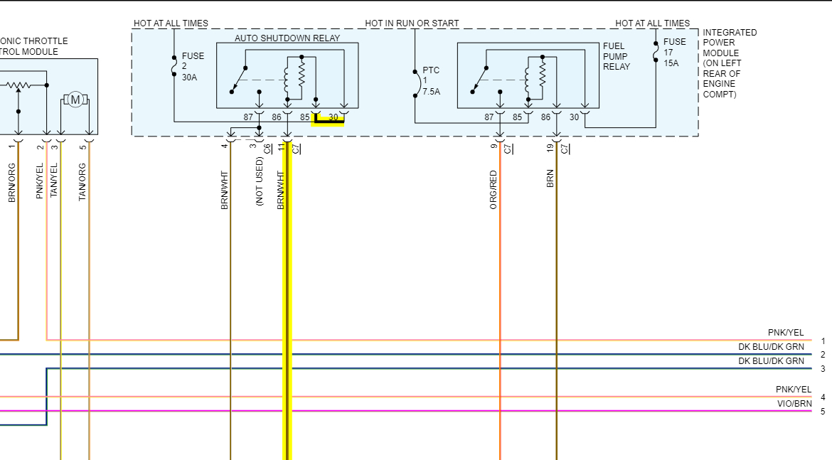
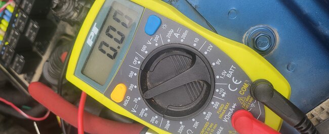
Okay. I'm sorry I didn't explain further, but pins 30 and 85 should have 12volts all the time, key on or off. They are hot at all times. Pin 86 is the pin that should be grounded when the relay is energized by the PCM. So, you can put one meter lead on battery negative and the other on pin 86, and if you have someone else first turn the key to just the on/run position you should read just about 0volts (or very low mv) for a couple of seconds.

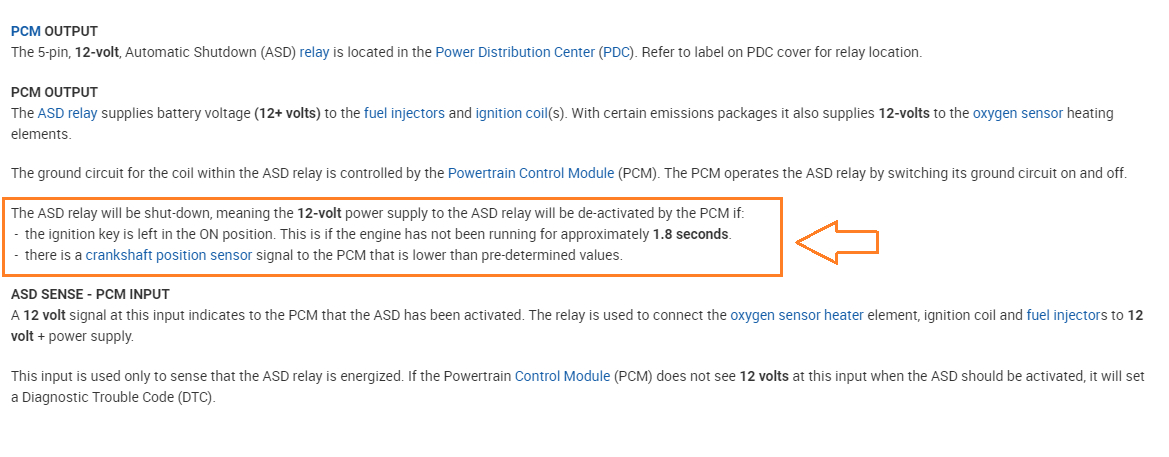
The PCM only energizes the relay for about 2 seconds at just key on. And then cranking you should read the same, a very low reading because the PCM should be grounding the relay during cranking, The ASD Relay powers up the Fuel Injectors and the Ignition Coils. Thats why when you jumped it the truck ran ok.

But if the PCM is not grounding pin 86, then that's an issue. If you find that it doesn't, then we will take it from there. It might be a bad relay, a wiring issue back to the PCM, or something else is causing the PCM to not energize the relay.

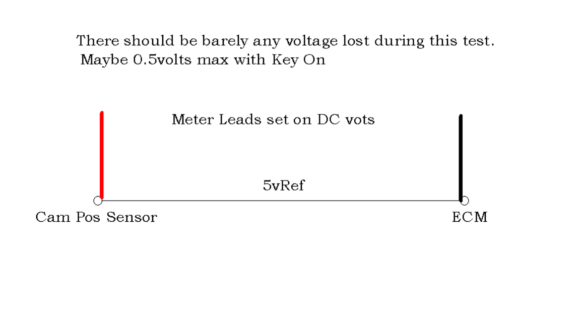
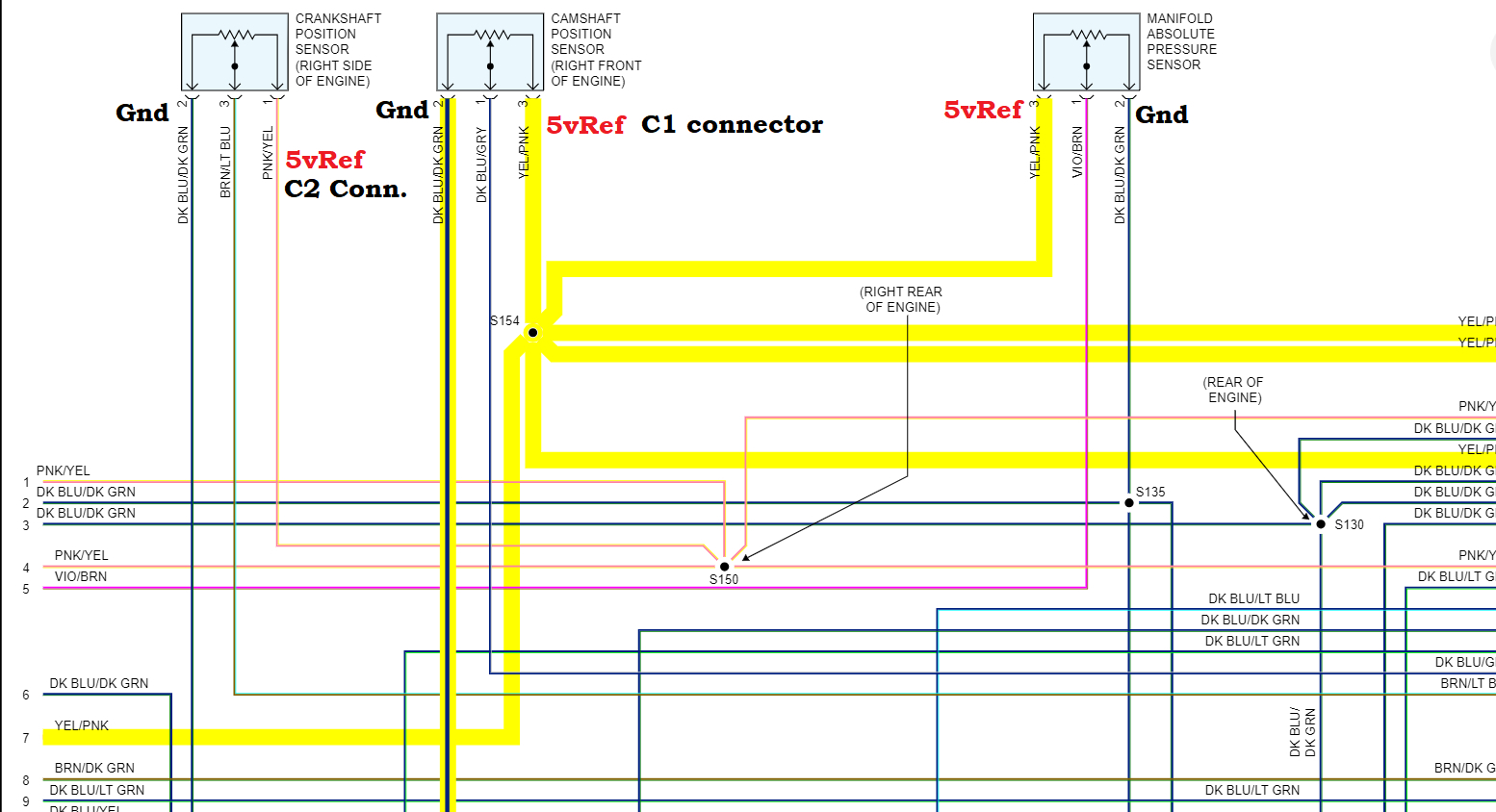
Below is just a very simple example of voltage drop testing, here you can see I am checking from a cam sensor to the ECM, I am measuring how much voltage is being lost from one point to another, that's all it is. But the circuit has to be on, you can't have any voltage drop unless some current is flowing between those 2 points.
So, if you want to check for voltage drop from Battery negative to the engine block or frame, you have to have at least the key on.

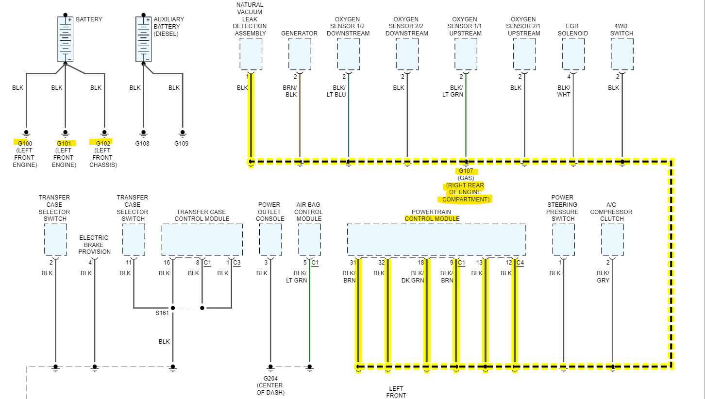
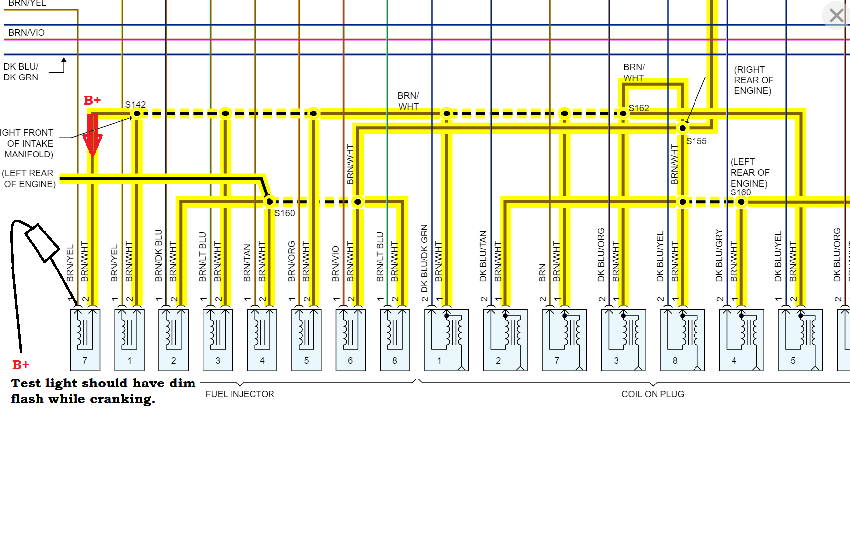
Thats the first simple explanation for it, it does get much more complicated in some situations, but for now, and easy test you can do with an incandescent 12v test light is to hook the test light clamp to Battery Positive and touch the test light tip to the engine block and then the body and frame.

The test light should light up brightly, because you have current flowing through the test light to Ground on the engine block, frame, and body. If it lights up very dim or not at all, you know you don't have a good ground from the battery to engine block, frame, body etc.
But do the first test with a meter in the first paragraph up top there and see if the PCM is grounding pin 86. You should be able to do that with the relay out. The PCM will set a code for the ASD relay in this case because it has a circuit that watches for power coming from the ASD relay, but for testing purposes we won't worry about that right now.
I'm going to see if any of the other relays on the truck are the same part number and if you can swap one out.
You should hear the ASD Relay click when you turn the key on or crank. Just put your finger on it and see if you notice and click. That doesn't tell if the relay is bad or not, but it can tell you if the PCM is in control of it.
Here is a guide on testing relays as well. Let me know what you find.

Okay, the ASD relay is the same part number as the A/C Compressor relay so you can try swapping them out really quick for a test.

https://www.2carpros.com/articles/how-to-check-an-electrical-relay-and-wiring-control-circuit
Was this
answer
helpful?
Yes
No
+1
Wednesday, August 2nd, 2023 AT 8:26 AM
Tiny
LONNIE CARR
  • MEMBER
  • 52 POSTS
Okay, here's what I did, I took out the ASD relay and hooked up the negative to the negative post and had my wife. Turn the key to the on off position. Then I touch the positive to the 86 pin at roughly the same time. And it went point 3 six, and then jumped to something. A different higher number and then back to point 36. Then I had her turn the Ignition to turn it over and did the same thing. And the numbers were the same point 3 six, roughly point 36. After it bounced up and then came back down.
Was this
answer
helpful?
Yes
No
Wednesday, August 2nd, 2023 AT 4:04 PM
Tiny
LONNIE CARR
  • MEMBER
  • 52 POSTS
Okay, here's what I did period I took out the ASD relay and hooked up the negative to the negative post and had my wife. Turn the key to the on off position. Then I touch the positive to the 86 pin at roughly the same time. And it went point 3 six, and then jumped to something. A differen. T higher number and then back to point 36. Then I had her turn the Ignition to turn it over and did the same thing. And the numbers were the same point 3 six, roughly point 36. After it bounced up and then came back down.
Was this
answer
helpful?
Yes
No
Wednesday, August 2nd, 2023 AT 4:04 PM
Tiny
LONNIE CARR
  • MEMBER
  • 52 POSTS
Afterwards, I hooked up the test light to the positive post and checked the block. The frame and the body and the light was bright on the test light the picture I sent you was what the multimedia red after. I had the Ignition completely on to run and tested it. Without anything else, that's what it was reading, and I showed you that I have my multi meter set the way I do. If that's incorrect, please let me know, thank you.
Was this
answer
helpful?
Yes
No
Wednesday, August 2nd, 2023 AT 4:07 PM
Tiny
AL514
  • MECHANIC
  • 4,125 POSTS
Okay, so, you had 0.48v on pin 86 with the meter going to battery negative when you turned the ignition switch to the on/run position and cranking? Did you try swapping the relay out with the A/C compressor relay? Actually, almost every relay that looks like the ASD Relay in this truck has the same part number, you just can't use the fuel pump relay because you need that to start the truck. But a voltage drop of 0.48v (about 1/2 a volt) is good. It should run with a different relay in there. Do you hear or feel that relay click when key On or cranking?
Was this
answer
helpful?
Yes
No
+1
Thursday, August 3rd, 2023 AT 7:30 AM
Tiny
LONNIE CARR
  • MEMBER
  • 52 POSTS
I swapped it out with every relay. That's in the box that fits. And no, it doesn't start unless I jump is the relay.
Was this
answer
helpful?
Yes
No
Thursday, August 3rd, 2023 AT 7:50 AM
Tiny
LONNIE CARR
  • MEMBER
  • 52 POSTS
I checked the throttle body and cleaned out some of the carbon. The lightning bolt comes on now after. And the check engine light comes on and stays on. I guess the lightning bolt flashes. I had to change the Ignition switch in the column in January. Cause the blower motor to quit. I finally the last part I changed. Was the Ignition switch and that was it? There are a couple burn marks where the Ignition switch plugs in. I added a snowplow in January. That's some nothing major.
Was this
answer
helpful?
Yes
No
Thursday, August 3rd, 2023 AT 8:00 AM
Tiny
AL514
  • MECHANIC
  • 4,125 POSTS
You didn't force the throttle plates open to clean them, did you? As for all these codes, erase them and see what comes back. Most of these were set while you had the relay out with the ignition switch on during testing. But forcing the throttle plates open on a drive by wire system can damage the electronic motor that controls the TAC (Throttle actuator). But do any codes come back with the relay in place, and everything normal?
Was this
answer
helpful?
Yes
No
+1
Thursday, August 3rd, 2023 AT 8:30 AM
Tiny
LONNIE CARR
  • MEMBER
  • 52 POSTS
I had P0562, and P0700 Pop-up, I also switched batteries from another vehicle that runs period Put a battery that had 12.5 V resting. I did not get a load reading off of it. Cranks over just fine did not start. Yes, I did mess with the actuator.
Was this
answer
helpful?
Yes
No
Friday, August 4th, 2023 AT 11:32 AM
Tiny
AL514
  • MECHANIC
  • 4,125 POSTS
Well, the throttle plates on these electronic throttle bodies are not supposed to forced open by hand, but what you can try to verify they are still opening ok is turn the key to the On/run position and have someone push on the gas pedal for you and you should see the throttle plates move, but yeah both of those codes are still low voltage codes.

Those burn marks on the ignition switch harness plug would be the next concern here, if the connector got that hot, there was high resistance in that location. Can you reach the plug you mentioned and try a wiggle test to see if that connection is having a pin fitment issue? Any time connectors get even warm, the first thing that comes to mind is pin and connector issues, even after the components changed out. With these voltage codes that needs to be checked. I'll see if I can find a diagram for the ignition switch and we'll check for power making it through. There might be some sections that are not sending a full 12volts or are breaking down under an electrical load.
Was this
answer
helpful?
Yes
No
+1
Friday, August 4th, 2023 AT 12:36 PM
Tiny
LONNIE CARR
  • MEMBER
  • 52 POSTS
Switched the new ignition switch out with the old one thinking that something else burnt out, No luck. The ignition switch I'm talking about is in the steering column. I will take pics. I wasn't keying on that because the pins that plug into the burn out, control the blower control switch and it works.
Was this
answer
helpful?
Yes
No
Friday, August 4th, 2023 AT 1:03 PM
Tiny
AL514
  • MECHANIC
  • 4,125 POSTS
Yeah, I was meaning the ignition switch on the column too. There wasn't any burn marks on the ignition switch harness plug?
Let's go back to the basics here. that will tell us if there something else going on with power to the PCM. You said in your first post the truck will run with starting fluid, correct? If so, then there is no fuel injector pulse.
With your test light hooked to battery negative, key On check for power at one of the fuel injector wires, if you have power, then hook the test light to battery positive and probe the other fuel injector wire, while someone cranks the engine over for you, the test light should have a dim pulse to it. The PCM should be pulsing the Ground (control) wire of the fuel injector, and this will cause the test light to pulse. If the test light does not pulse at all, there is no injector control. This is an injector guide below, but we just need to know there is power to the injectors for one, and then know that the control side is being pulled to ground by the PCM,
It can be a quick 5 min test. and we'll know there's no injector control. You had enough fuel pressure, so really, we should have started with the basics first, but that's okay, let's see what you get.

The 5v Reference feed for the Crankshaft position sensor looks to be a different 5vRef than the one for the Camshaft position sensor. So, it might be the cam sensor that's not working.

https://www.2carpros.com/articles/how-to-test-a-fuel-injector
Was this
answer
helpful?
Yes
No
+1
Friday, August 4th, 2023 AT 1:18 PM
Tiny
LONNIE CARR
  • MEMBER
  • 52 POSTS
There might be more of a problem than I realized. After looking a little closer, this is what I've got. The line on the left is actually a red wire. It is burnt about an inch up the Wire, the other one is a blue wire.
Was this
answer
helpful?
Yes
No
Friday, August 4th, 2023 AT 1:54 PM
Tiny
AL514
  • MECHANIC
  • 4,125 POSTS
Oh wow, there's the problem, in that second picture the green corrosion, those overheated connector pins. This is the ignition switch connector, correct?
That green corrosion is causing resistance and overheating those wires. The red wires are the feed from the fuse panel and the other colored wires are the output wires.

I would replace that entire connector, get a new pigtail for the switch.
Here's the pinout for the ignition switch connector.
Was this
answer
helpful?
Yes
No
+1
Friday, August 4th, 2023 AT 1:57 PM
Tiny
LONNIE CARR
  • MEMBER
  • 52 POSTS
AL514 thank you. Times are tough right now and you and this website have helped me tremendously. I can't afford to pay someone to fix this so who knows how long it would have taken me to get this far without your help. I know what's not fixed yet for sure, but you still been a big help, and I can't say thank you enough. Hopefully I will change this out and everything will be good again.
Was this
answer
helpful?
Yes
No
Friday, August 4th, 2023 AT 2:18 PM
Tiny
AL514
  • MECHANIC
  • 4,125 POSTS
No worries, glad to help. If you want to verify after the fix, you can see on the switch pinout the Fused B+, those are the battery input feeds (Red wires), and the other wires are the Outputs, so you can make sure that you have 12 full volts coming out of each wire. Use a test light because it puts a small load on the circuit.
Was this
answer
helpful?
Yes
No
+1
Friday, August 4th, 2023 AT 2:36 PM
Tiny
LONNIE CARR
  • MEMBER
  • 52 POSTS
AL514, I changed connectors, and nothing changed. I'm going to test an injector tonight. Would you tell me how to test the camshaft sensor and where it would be located? Thank you
Was this
answer
helpful?
Yes
No
Tuesday, August 8th, 2023 AT 2:28 PM
Tiny
AL514
  • MECHANIC
  • 4,125 POSTS
Hello, sorry for my delay, I just got power and internet back on today due to the huge storm that hit a couple days ago.
Okay, did you check for power going in on the red wires and power coming out on all the other colored wires? I'm writing up a testing diagram for you, there is this one circuit I'm concerned with, it's this "Key in Ignition Switch Sense" circuit. Service info states it opens and closes a Ground circuit for a Central Timer Module. So, I'm not sure if that is the Ground labelled on the Ignition switch connector diagram or a different one. But you can check if the pin 6 (Ground) opens and closes a ground circuit with putting the key in the ignition and taking it out, I'm labelling all these other Outputs to check as well because some of them are only hot in either Start/Cranking or on/run.
The concern would be that with the harness connector getting as hot as it did, there might be some damage we just can't see. So I'll have you check all these B+ inputs and Outputs first from the connector, Im just checking where this sense circuit goes first,

We're still at just a Crank No Start condition, correct?

Here is the voltage input/output testing for that ignition switch connector. Check this first, then we're just going to go right to the PCM for testing to see what's missing.

Now when back probing the PCM connectors you have to be very careful, using a T pin or back probing pin, very easily slide the T pin along the wire into the connector you're testing. We need the PCM connectors to be plugged in to see if the PCM is receiving the voltage it's supposed to. You may have to remove the back cover of the PCM connectors to do this, but don't force them, just probe far enough to get a reading. Use a multimeter hooked to battery negative for both power and ground testing. Write down the results of each pin. There's not that many to check, I've noted what should be there and the one that is a cranking test. If you don't know, what back probing pins are I can post a picture if needed but let's just go right to the source here and see if the PCM is missing any power or grounds. Let me know if you have any questions

Go through and check for any blown fuses as well, that ignition switch looks like it may have shorted out, connectors don't get that hot without doing more damage.
Was this
answer
helpful?
Yes
No
+1
Wednesday, August 9th, 2023 AT 1:24 PM

Please login or register to post a reply.

Sponsored links