Welcome to 2CarPros.
First, it isn't uncommon for the tire pressure monitors to fail. They each have a separate battery that usually lasts about 5 years. However, make sure the pressure is at what is listed inside the driver's door on the tire information label. The only way to confirm that is with a TPMS scanner which can tell you if there is a signal from the sensor.
Next, I feel somewhat confident the ABS and Traction control lights which are both on have something to do with a bad wheel speed sensor. The ABS and TC are tied together. If one fails, the other will. With that in mind, I suggest testing the wheel speed sensors. Here is a link that shows how it is done. Other than this type of test, you will need a live data scanner that can read ABS codes:
https://www.2carpros.com/articles/abs-wheel-speed-sensor-test
Here is a short video showing how it is done:
https://youtu.be/jG18XmUJoNU
That is the first thing I would check. Also, here are a few links you may find helpful:
https://www.2carpros.com/articles/how-to-use-a-test-light-circuit-tester
https://www.2carpros.com/articles/how-to-use-a-voltmeter
https://www.2carpros.com/articles/how-to-check-wiring
https://www.2carpros.com/articles/abs-brake-system-repair
https://www.2carpros.com/articles/how-to-replace-an-abs-wheel-speed-sensor
______________________________
I know that seems like a lot of information, but I added it in case you need it. If you find one of the sensors is bad, here are the directions for replacing it. I will start with the front and then the rear. All attached pictures correlate with these directions.
_____________________________
Front:
REMOVAL
BRAKE CONTROL: FRONT SPEED SENSOR: REMOVAL
HINT
* Use the same procedure for the RH and LH sides.
* The procedures listed below are for the LH side.
1. DISCONNECT CABLE FROM NEGATIVE BATTERY TERMINAL
CAUTION:
Wait at least 90 seconds after disconnecting the cable from the negative (-) battery terminal to disable the SRS system.
2. REMOVE FRONT WHEEL
3. REMOVE FRONT FENDER LINER LH
HINT
It is not necessary to fully remove the fender liner. Partially remove it so that the speed sensor connector can be disconnected in a later step.
4. REMOVE FRONT SPEED SENSOR LH
(a)Disconnect the sensor connector.
picture 1
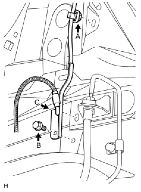
(b)Remove the sensor clip (labeled A), bolt (labeled B) and sensor clamp (labeled C).
picture 2
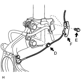
(c)Remove the sensor clip (labeled D), bolt (labeled E) and sensor clamp (labeled F).
picture 3
(d)Remove the bolt and sensor body from the knuckle.
picture 4
NOTICE:
Keep the sensor tip and sensor installation hole free from foreign matter.
__________________
INSTALLATION
BRAKE CONTROL: FRONT SPEED SENSOR: INSTALLATION
HINT
* Use the same procedure for the RH and LH sides.
* The procedures listed below are for the LH side.
1. INSTALL SPEED SENSOR FRONT LH
NOTICE:
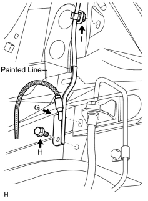
To prevent interference with other parts, do not twist the painted line areas of the sensor wire when installing it.
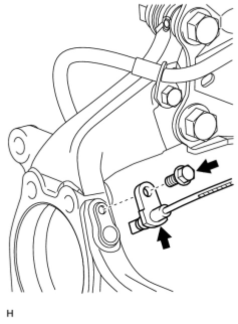
(a)Set the sensor body into the knuckle, and then install the sensor with the bolt.
picture 5
Torque : 8.5 Nm (87 kgf-cm, 75 in-lbf)
NOTICE:
* Keep the sensor tip and sensor installation hole free from foreign matter.
* Firmly insert the sensor body into the knuckle before tightening the bolt.
* After installing the sensor to the knuckle, make sure that there is no clearance between the sensor stay and knuckle. Also make sure that no foreign matter is stuck between the parts.
* To prevent interference between the sensor and magnetic rotor, do not rotate the sensor body during or after the insertion of the sensor body to the knuckle.
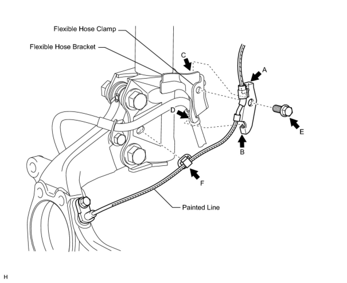
(b)Install the sensor clamp and sensor clip as follows.
picture 6
(1)Simultaneously perform the following: 1) hang the hook part of the sensor clamp (labeled A) on the flexible hose bracket (labeled C); and 2) insert the hook part of the sensor clamp (labeled B) into the flexible hose bracket (labeled D).
NOTICE:
Do not twist the sensor wire when installing the clamp.
(2)Install the sensor clamp to the flexible hose clamp and flexible hose bracket with the bolt (labeled E).
Torque : 19 Nm (189 kgf-cm, 14 ft-lbf)
(3)Insert the sensor clip (labeled F) into the hole on the absorber lower bracket.
(c)Install the sensor clamp and sensor clip as follows.
picture 7
(1)Set the sensor clamp (labeled G) on the side member, and then install the bolt (labeled H).
Torque : 8.5 Nm (87 kgf-cm, 75 in-lbf)
NOTICE:
Do not twist the sensor wire when installing the clamp.
(2)Insert the sensor clip (labeled I) into the hole on the apron.
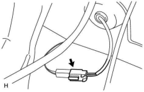
(d)Connect the sensor connector.
picture 8
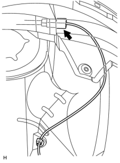
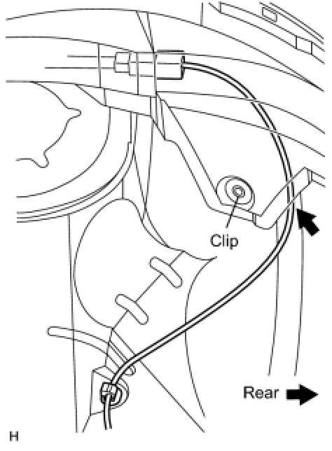
2. INSTALL FRONT FENDER LINER LH
picture 9
HINT
Install the fender liner so that the sensor wire harness passes beyond the fender liner installation clip towards the rear side of the vehicle.
3. INSTALL FRONT WHEEL
Torque : 103 Nm (1050 kgf-cm, 76 ft-lbf)
4. CONNECT CABLE TO NEGATIVE BATTERY TERMINAL
5. CHECK ABS SPEED SENSOR SIGNAL
(a)Check the speed sensor signal See: Antilock Brakes / Traction Control Systems > Scan Tool Testing and Procedures > Test Mode Procedure.
_____________________________________________
Rear
REMOVAL
BRAKE CONTROL: REAR SPEED SENSOR (for 2WD): REMOVAL
HINT
* Use the same procedure for the RH and LH sides.
* The procedures listed below are for the LH side.
1. DISCONNECT CABLE FROM NEGATIVE BATTERY TERMINAL
CAUTION:
Wait at least 90 seconds after disconnecting the cable from the negative (-) battery terminal to disable the SRS system.
2. REMOVE REAR WHEEL
3. REMOVE DECK TRIM SIDE PANEL ASSEMBLY LH
(a)Remove the deck trim side panel LH See: Headliner > Removal and Replacement > Removal.
4. REMOVE REAR SPEED SENSOR WIRE
(a)Disconnect the skid control sensor wire connector.
picture 10
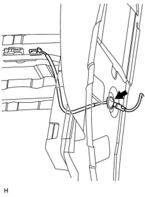
(b)Disconnect the grommet of the skid control sensor wire from the hole of the wheel house.
picture 11
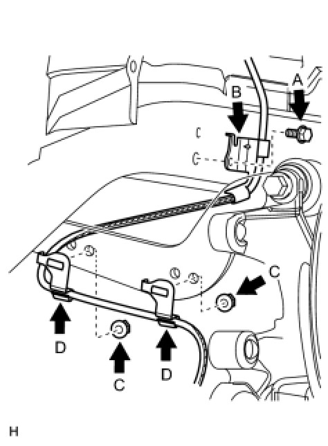
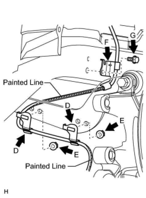
(c)Remove the bolt (labeled A) and sensor clamp (labeled B) from the side member.
picture 12
(d)Remove the 2 nuts (labeled C) and 2 sensor clamps (labeled D) from the upper arm.
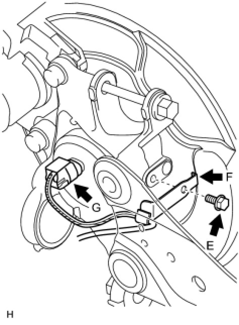
(e)Remove the bolt (labeled E) and sensor clamp (labeled F) from the carrier.
picture 13
(f)Disconnect the skid control sensor wire connector (labeled G) from the skid control sensor.
5. REMOVE REAR DISC BRAKE CYLINDER ASSEMBLY LH See: Disc Brake System > Overhaul > Disassembly
6. REMOVE REAR DISC See: Disc Brake System > Overhaul > Disassembly
7. REMOVE REAR AXLE HUB AND BEARING ASSEMBLY LH (SKID CONTROL SENSOR)
(a)Remove the rear axle hub and bearing LH See: Wheel Hub > Removal and Replacement > Removal.
______________
INSTALLATION
BRAKE CONTROL: REAR SPEED SENSOR (for 2WD): INSTALLATION
HINT
* Use the same procedure for the RH and LH sides.
* The procedures listed below are for the LH side.
1. INSTALL REAR AXLE HUB AND BEARING ASSEMBLY LH (SKID CONTROL SENSOR)
(a)Install the rear axle hub and bearing LH See: Wheel Hub > Removal and Replacement > Installation.
2. INSTALL REAR DISC See: Disc Brake System > Overhaul > Reassembly
3. INSTALL REAR DISC BRAKE CYLINDER ASSEMBLY LH See: Disc Brake System > Overhaul > Reassembly
4. INSTALL SKID CONTROL SENSOR WIRE
NOTICE:
To prevent interference with other parts, do not twist the painted line areas of the sensor wire when installing it.
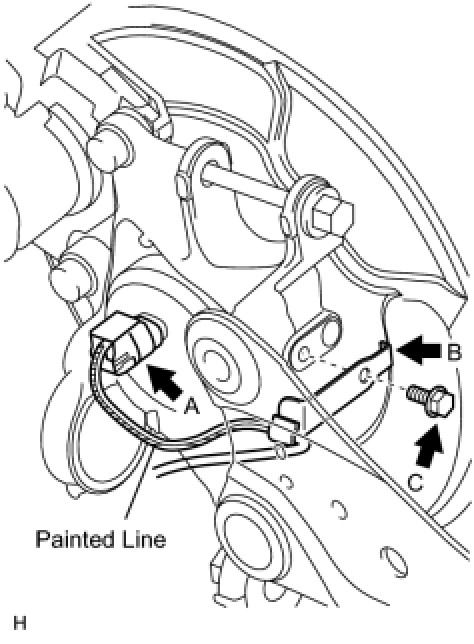
(a)Connect the skid control sensor wire connector (labeled A) to the skid control sensor.
picture 14
(b)Install the sensor clamp (labeled B) with the bolt (labeled C).
Torque : 8.5 Nm (87 kgf-cm, 75 in-lbf)
NOTICE:
Do not twist the sensor wire when installing the clamp.
(c)Install the 2 sensor clamps (labeled D) with the 2 nuts (labeled E).
picture 15
Torque : 5.0 Nm (51 kgf-cm, 44 in-lbf)
NOTICE:
Do not twist the sensor wire when installing the clamps.
(d)Install the sensor clamp (labeled F) with the bolt (labeled G).
Torque : 8.5 Nm (87 kgf-cm, 75 in-lbf)
NOTICE:
Do not twist the sensor wire when installing the clamp.
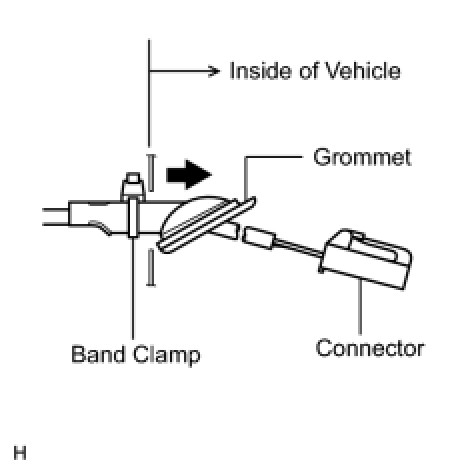
(e)Insert the connector and grommet into the inside of the vehicle through the hole in the wheel house.
picture 16
NOTICE:
Make sure the grommet band clamp remains on the outside of the vehicle.
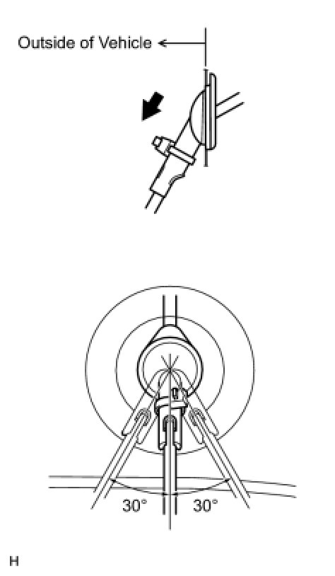
(f)Hold the grommet and pull it toward the outside of the vehicle. Then fix the grommet in place so that it is not tilted.
picture 17
NOTICE:
* When pulling out the grommet, do not grip the sensor wire.
* Fix the grommet in place within the range shown in the illustration.
(g)Connect the skid control sensor wire connector.
picture 18
5. INSTALL DECK TRIM SIDE PANEL ASSEMBLY LH
(a)Install the deck trim side panel LH See: Headliner > Removal and Replacement > Installation.
6. INSTALL REAR WHEEL
Torque : 103 Nm (1050 kgf-cm, 76 ft-lbf)
7. CONNECT CABLE TO NEGATIVE BATTERY TERMINAL
8. CHECK SPEED SENSOR SIGNAL
(a)Check the speed sensor signal See: Antilock Brakes / Traction Control Systems > Scan Tool Testing and Procedures > Test Mode Procedure.
__________________________________________________________
Let me know if you have other questions, need help, and what you find.
Take care,
Joe
Images (Click to make bigger)
Saturday, April 6th, 2019 AT 9:09 PM