A wheel rotation speed sensor is easy to test using a simple voltage meter. In this guide we will walk you through the testing which works well when you don't have a code scanner and the ABS and Traction control warning lights are on. Most of the time the a wheel speed sensor will be the problem.
Supplies Needed
- Voltmeter
- Basic Tools
- Floor Jack
- Lug Wrench
Before you begin, park the car on level ground and block the wheels so the car does not move. Lift the end of the car you wish to test, use jack stands for added safety and remove the wheel if needed.
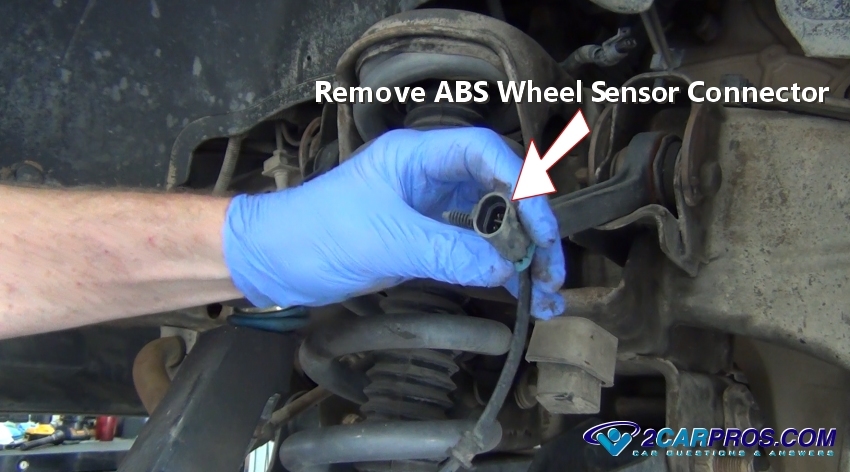
1. Locate the electrical connector from a particular the wheel speed sensor which is near the frame or in the wheel-well in most cases. Don't be confused by other wiring harnesses that may lead down to the wheel such as the brake pad wear sensor. Once located, disconnect the sensor wire at the connector by releasing the safety clasp and gently pulling it apart.
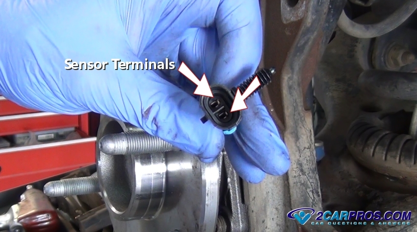
2. Observe the terminals inside the sensor connector, this is where the voltmeter leads will be connected too.
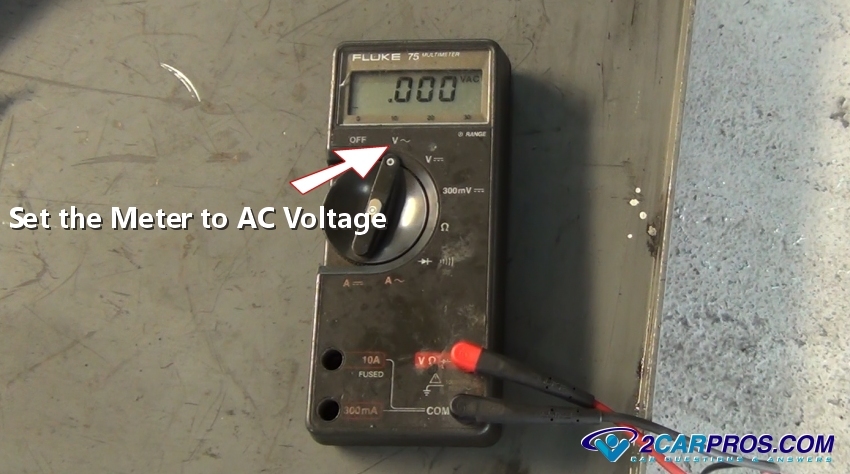
3. Set the voltmeter to AC voltage and use the alligator leads to attach to the sensor connector terminals. Be sure to not allow these test probes to touch together or the sensor will not test properly. Try not to use hand held probes because they can wiggle causing the voltmeter readings to fluctuate which makes testing more difficult and can offset the test.
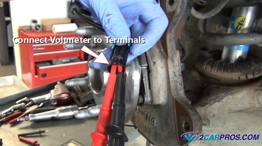
4. The meter will usually indicate AC voltage by a wave symbol. Once the meter is turned on it will fluctuate down to zero volts. Now the sensor is ready to be tested.
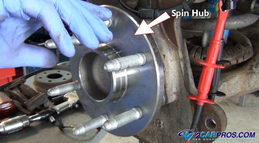
5. While observing the voltmeter spin the wheel or hub to create voltage. This voltage will vary according to the speed in which the hub or wheel is spun. As the hub begins to spin the voltage will rise and then decrease as it stops. Spin the hub or axle which will produce the voltage, if no readings can be found the sensor has failed and replacement is required.
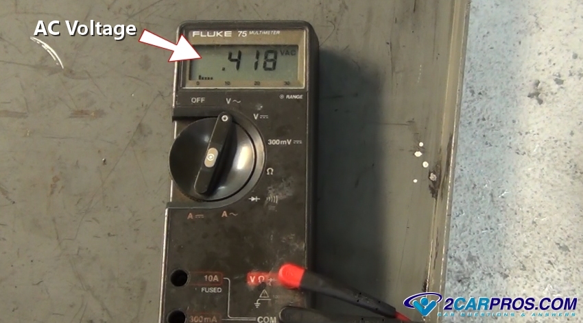
6. This is a typical reading from a wheel sensor, configuration of the sensor mounting is different for each manufacturer but follow the same operation.
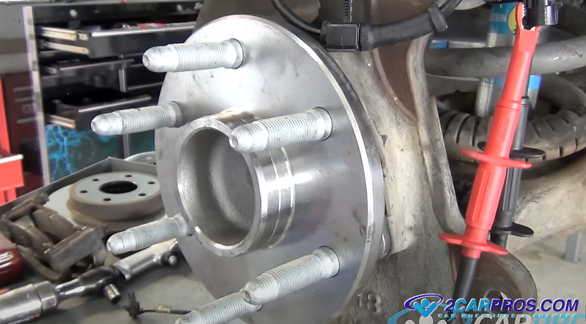
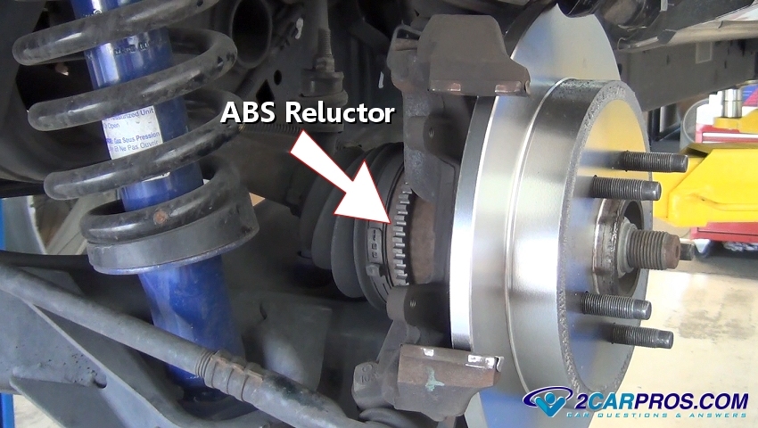
7. In the image below a stator ring or as it is sometimes called a reluctor can be located inside the bearing hub, rear axle housing, or on the CV joint itself. Slowly rotate the ring to check it for damage or missing teeth. Wheel sensors are magnetic so check for metal shavings around the sensor which can hinder performance which should be cleaned off.
8. If you have gone through all these steps and you still have a code for one of the sensors, the only other possibility is an open circuit somewhere in the wiring which can be found by a pin to pin check which tests the wiring. You will need to use a specific wiring diagram with a voltmeter set to ohms of resistance to check each wire from end to end. This will help detect a broken or shorted wire, once repaired it should turn the light off. This is an example of an ABS sensor wiring diagram.
Watch the Video!
Please watch this video of the job being done to glean additional helpful information.
Credits
This guide knowledge base was created by the 2CarPros Team, and by Ken Lavacot: Automobile repair shop owner and certified master automobile technician of over 30 years. If you have question or need help please ask one of our experts we are happy to help. Please visit our 2CarPros YouTube Channel.