Codes P0340 and P0344, can I get a diagram of the camshaft position sensor?

Tiny
DANNYBOY5474
  • MEMBER
  • 2006 FORD F-150
  • 5.4L
  • V8
  • 2WD
  • AUTOMATIC
  • 220,000 MILES
Has code P0340 and P0344. Sensor was replaced and the problem still exists. Thanks
Thursday, May 22nd, 2025 AT 5:55 PM

22 Replies

Tiny
STEVE W.
  • MECHANIC
  • 15,233 POSTS
It's a simple circuit. The gray with red wire is the ground side of the sensor; the dark green is the signal to the PCM. As you don't have a code for the other cam sensor, I suspect the issue is the green wire or the PCM itself. I would start at the connector and check pin fitment. Loose or bad contacts are common. The PCM failing is also common.
Was this
answer
helpful?
Yes
No
Friday, May 23rd, 2025 AT 12:18 AM
Tiny
DANNYBOY5474
  • MEMBER
  • 39 POSTS
Thanks for the reply. I'll get back to you after I check.
Was this
answer
helpful?
Yes
No
Friday, May 23rd, 2025 AT 2:57 AM
Tiny
KEN L
  • MASTER CERTIFIED MECHANIC
  • 54,137 POSTS
Sounds good, STEVE W. Is one of our best!
Was this
answer
helpful?
Yes
No
Sunday, May 25th, 2025 AT 10:31 AM
Tiny
DANNYBOY5474
  • MEMBER
  • 39 POSTS
Just curious. Steve is the other wire (I believe green) in pin #44?
Was this
answer
helpful?
Yes
No
Tuesday, June 17th, 2025 AT 5:20 PM
Tiny
STEVE W.
  • MECHANIC
  • 15,233 POSTS
Dark green should be in #45. Pin 44 is for sensor 2.
Was this
answer
helpful?
Yes
No
Tuesday, June 17th, 2025 AT 5:26 PM
Tiny
DANNYBOY5474
  • MEMBER
  • 39 POSTS
Okay, diagram you provided shows gray/red in pin #45.
Was this
answer
helpful?
Yes
No
Tuesday, June 17th, 2025 AT 5:30 PM
Tiny
DANNYBOY5474
  • MEMBER
  • 39 POSTS
I want to check resistance/continuity in both wires through the harness to PCM. After that will check voltage in both wires with KOEO.
Was this
answer
helpful?
Yes
No
Tuesday, June 17th, 2025 AT 5:37 PM
Tiny
STEVE W.
  • MECHANIC
  • 15,233 POSTS
Gray red is the ground for all the sensors and is on pin 1 in each cam sensor. For sensor 1 there is a dark green that goes into pin 45 on the PCM. You would want to look at the continuity from pin45 to pin 2 in the sensor connector. Then to check the ground side go to the other cam sensor and check for continuity between both pin ones in the connectors. The sensors are both simply coils of wire wrapped around a metal core. As the camshaft rotates the reluctor on the end where the sensor is passes the tip of the sensor and generates a small pulse. The PCM sees the pulses and counts them to determine camshaft position. If your meter can read millivolts, you might see the voltage the sensor generates.
Was this
answer
helpful?
Yes
No
Tuesday, June 17th, 2025 AT 9:44 PM
Tiny
DANNYBOY5474
  • MEMBER
  • 39 POSTS
Ok thanks! This helps more. Will check and get back to you.
Was this
answer
helpful?
Yes
No
Wednesday, June 18th, 2025 AT 8:36 PM
Tiny
KEN L
  • MASTER CERTIFIED MECHANIC
  • 54,137 POSTS
STEVE W. Is one of our best! Please let us know.
Was this
answer
helpful?
Yes
No
Thursday, June 19th, 2025 AT 9:51 AM
Tiny
DANNYBOY5474
  • MEMBER
  • 39 POSTS
So, I used a DVOM to test the wires. On the gry/rd from connector to PCM the wire had continuity, but I couldn't get anything on the green wire connector to PCM. Also, with KOEO there was no battery voltage at the connector. Any thoughts?
Was this
answer
helpful?
Yes
No
Thursday, June 19th, 2025 AT 4:42 PM
Tiny
STEVE W.
  • MECHANIC
  • 15,233 POSTS
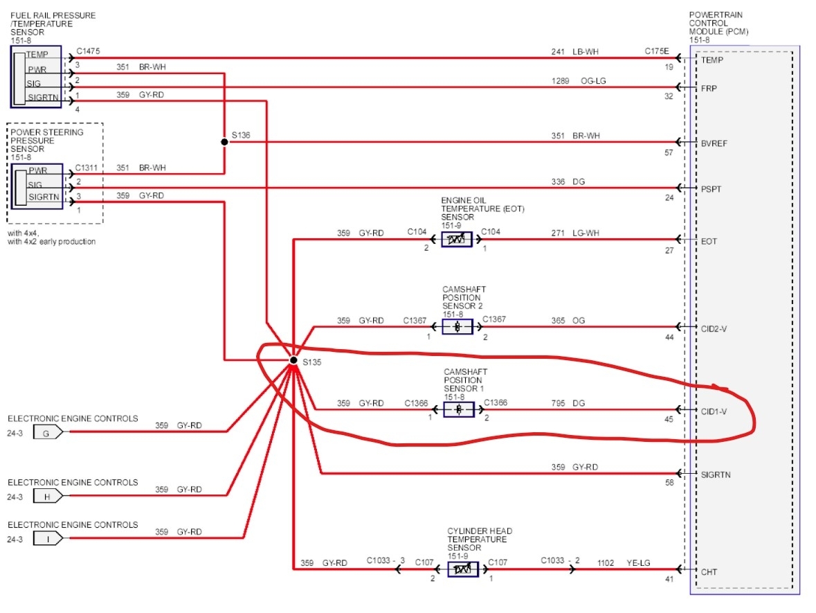
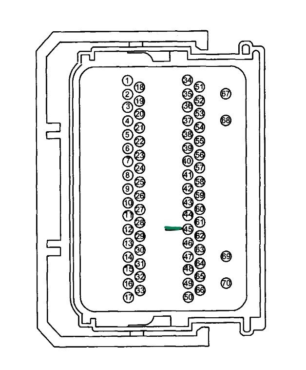
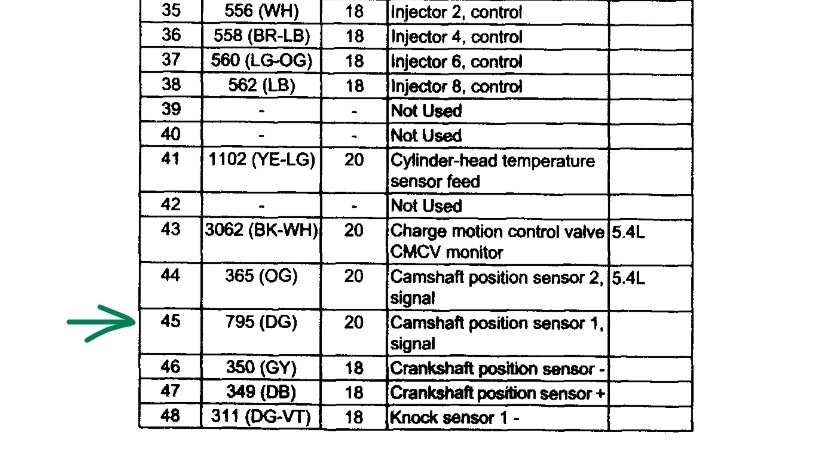
There won't be voltage there, the sensor generates the voltage itself. If you have no continuity on the dark green from pin 2 on the sensor connector to pin 45 on the ECM, that is the issue. An easy way to be sure is to check pin one in the connector to ground. Then jump pins one and two in the connector and now go to pin 45 and check if it is grounded in that connector. No ground, it's an open wire. It's going to be a pain, but you can open the loom and trace the wire, or much simpler. Get a section of new wire and replace the bad one. To see if the issue would let you simply splice into the wire, take your meter and a pin, go about 6 inches from the connector on one end and push the pin into the wire center. Now test, if you have continuity, cut the wire where the pin is and strip it back a bit. Now go to the ECM end and do the same. Now you can add in the new wire between those pieces.
Was this
answer
helpful?
Yes
No
Thursday, June 19th, 2025 AT 6:17 PM
Tiny
DANNYBOY5474
  • MEMBER
  • 39 POSTS
Do you by chance have a numbered Pic of the PCM harness connector #45? The connector isn't numbered. Thanks again.
Was this
answer
helpful?
Yes
No
Thursday, June 19th, 2025 AT 7:57 PM
Tiny
STEVE W.
  • MECHANIC
  • 15,233 POSTS
Try this. It's a black 70 pin connector 175E. Pin 44 is an orange wire (cam 2) #45 is dark green (cam 1) 46 is gray (crank 1)
Was this
answer
helpful?
Yes
No
Friday, June 20th, 2025 AT 8:26 AM
Tiny
DANNYBOY5474
  • MEMBER
  • 39 POSTS
So, I was able to get continuity in all 4 for wires gray/red (ground) and dk grn (sensor 1- problem) and orange sensor 2. Is there a way/ idea to test with KOEO or KOER? Maybe PCM problem? Thanks
Was this
answer
helpful?
Yes
No
Friday, June 27th, 2025 AT 4:11 PM
Tiny
STEVE W.
  • MECHANIC
  • 15,233 POSTS
Okay, if the wires check out, and you had 2 sensors showing faults it leaves only the PCM itself as the likely failed item. There are no other tests involved, unless you have a scope handy. With that you could probe the sensor and run the engine to see if the sensor is putting out the proper signal. Then check for that same signal at the PCM. If it's there, then you know it's the PCM. You might see an AC voltage if your meter is sensitive enough, Put the leads on the sensor terminals of sensor 2 (the one that works) run the engine and see what it shows. Repeat on the bad sensor. Should be the same.
Was this
answer
helpful?
Yes
No
Friday, June 27th, 2025 AT 4:50 PM
Tiny
DANNYBOY5474
  • MEMBER
  • 39 POSTS
The code was only for sensor#1.
Was this
answer
helpful?
Yes
No
Friday, June 27th, 2025 AT 5:34 PM
Tiny
DANNYBOY5474
  • MEMBER
  • 39 POSTS
Sensor was replaced with new one also.
Was this
answer
helpful?
Yes
No
Friday, June 27th, 2025 AT 5:35 PM
Tiny
STEVE W.
  • MECHANIC
  • 15,233 POSTS
Yes, but the new one could be bad, but the idea is to test the "good" sensor in position 2 and see if you get any reading of AC volts. Then reconnect it and test number 1. If you see the same reading on one that you saw on 2 then you know the sensor is working and generating a signal. So, say you connect to sensor 2 and see a volt of AC at idle that goes up to 3 volts at 3000 rpm. Now you probe sensor 1 and see the same voltages, now you know that the sensor and reluctor are okay. Now you can also back probe the two wires from the sensor at the PCM, seeing the same voltage at the PCM? Wiring is good and the problem is in the PCM itself.
Was this
answer
helpful?
Yes
No
Saturday, June 28th, 2025 AT 12:45 AM
Tiny
DANNYBOY5474
  • MEMBER
  • 39 POSTS
Ok, how do I test?
Was this
answer
helpful?
Yes
No
Sunday, June 29th, 2025 AT 9:18 PM

Please login or register to post a reply.