Overheating issue due to no fans running

Tiny
MAEMOND
  • MEMBER
  • 2008 HONDA CIVIC HYBRID
  • 1.3L
  • 4 CYL
  • 2WD
  • AUTOMATIC
  • 160,000 MILES
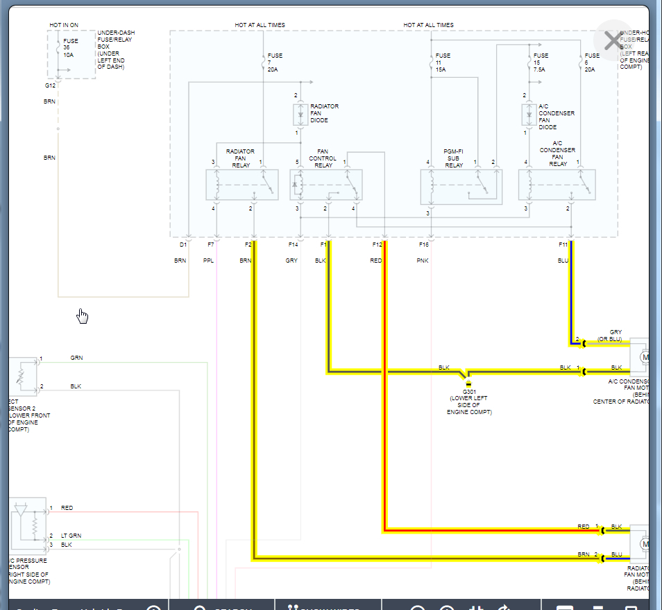
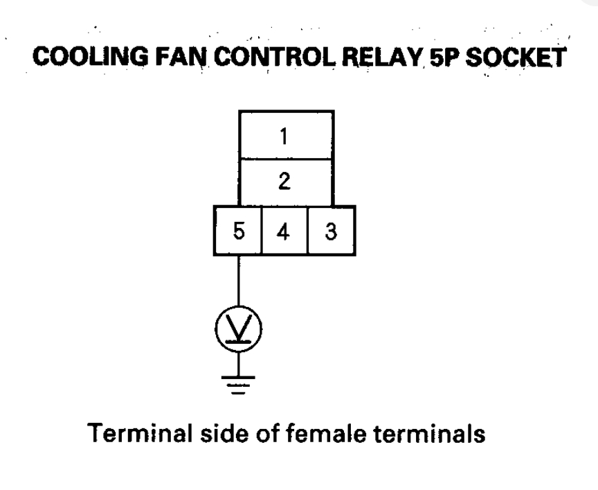
Both fans are not coming on. I have tested both fans directly and they both work. All fuses check okay. I have replaced the fan switch thinking that was it, but it was not. Just a bad conclusion on my part. Relays are good. So, this is where I am at. Switch is good. Fan is good. When I jumped the fan switch connector, I get nothing. The one pin out has connectivity to the blue wire that leads to the fan. The other pin out on the switch connector seems to have continuity when I have the key in the on position. I tested with a meter, negative on the battery, positive on that pin and I did get a reading. I did not get a reading when the key was in the off position.

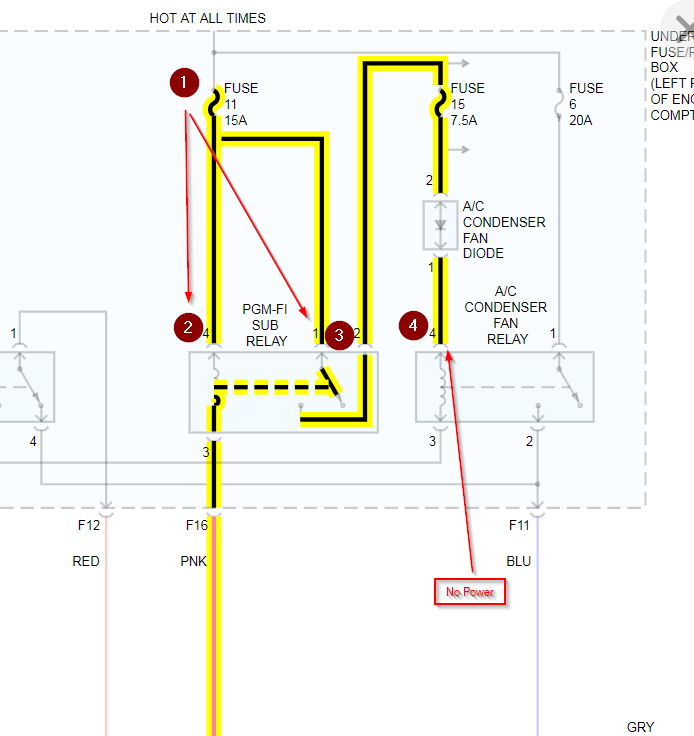
I have done little testing on the A/C fan side. I have confirmed the fan works. I also jumped the 1 and 2 pins and the A/C fan did come on. That is the extent of my testing.
Do you
have the same problem?
Yes
No
Sunday, June 28th, 2020 AT 9:48 PM

83 Replies

Tiny
KASEKENNY
  • MECHANIC
  • 18,907 POSTS
Take a look at the wiring diagram. When you say you jumped pin 1 and 2 and the fan came on, I assume you mean of the radiator fan relay?

Also, when you turn on the A/C does your condenser fan come on at all?

These are only connect or related through the PCM. Basically the PCM grounds both relays to turn the fans on. So we need to turn them all on and test the wiring coming from the PCM. I suspect you don't have power on that wire. Which means either the PCM is not functioning or something is telling the PCM that the fans are not needed. This is why we need to confirm that neither fan is working with the A/C on. This would point away from an ECT issue.

Let us know what you find with this info and we can go from there. Thanks
Was this
answer
helpful?
Yes
No
Monday, June 29th, 2020 AT 3:32 PM
Tiny
MAEMOND
  • MEMBER
  • 54 POSTS
When I turn on the A/C, no fans turn on. When I tested the relay outlet for the radiator fan, pin 1 had power. Pin 2 goes to the fan and runs when I jumper pin 1. Pin 3 has power when key is in the on position. Fan runs when pins 2 and 3 are jumped. Pin 4 no power.

The relay with the A/C and radiator symbols on it, all I have done is jumped pins 1 and 2 to rule out that the fans do work.
Was this
answer
helpful?
Yes
No
Monday, June 29th, 2020 AT 11:36 PM
Tiny
MAEMOND
  • MEMBER
  • 54 POSTS
How do I go about testing the PCM?
Was this
answer
helpful?
Yes
No
Tuesday, June 30th, 2020 AT 12:51 AM
Tiny
KASEKENNY
  • MECHANIC
  • 18,907 POSTS
Sounds like you already did. However, the way to confirm this is to test to see if the PCM can ground a 12 volt circuit. Remove the relay and put your negative meter lead on the 4 terminal. Then put the red lead on the positive post of the battery for the 12 volt source. Then turn the engine on and AC on so that both fans will come on. You meter should read 12 volts if the PCM is able to ground the circuit. If not, then PCM is suspect.

Take a look at the wiring diagram.
Was this
answer
helpful?
Yes
No
Tuesday, June 30th, 2020 AT 6:29 PM
Tiny
MAEMOND
  • MEMBER
  • 54 POSTS
There’s three relays. Radiator fan, A/C fan, and a radiator and A/C fan relay. Which one should I be checking?
Was this
answer
helpful?
Yes
No
Tuesday, June 30th, 2020 AT 10:45 PM
Tiny
MAEMOND
  • MEMBER
  • 54 POSTS
So, with checking just the A/C relay slot, with pin 4, positive on the battery, and negative on the pin. I am getting no reading. Ignition is in the on position with A/C on. I can hear the blower fan going. No cooling fans are running.
Was this
answer
helpful?
Yes
No
Wednesday, July 1st, 2020 AT 11:46 AM
Tiny
KASEKENNY
  • MECHANIC
  • 18,907 POSTS
You are correct that you have 3 relays. However, the PCM only actually grounds two of the relays because the Fan Control relay and the AC condenser relay control sides are tied together on the same circuit from the PCM. The third wire coming from the PCM (First wiring diagram with the black arrows) is to ground the PGM relay.

To address what you are seeing with not having voltage on pin 4 of the AC fan relay we need to look at the second wiring diagram.

The power starts at where I added number 1. We need to check fuse 11 to make sure you have power there. Then follow power down to number 2. The PCM grounds this relay on terminal 3 of the PGM relay. When this is grounded, the relay closes and power goes from terminal 1 of the relay to terminal number 2 of the relay (where I added number 3). It then goes to fuse 15 and then through the diode finally to number 4 that I added (also terminal 4 of the AC relay) which is where you are not getting power.

So you need to go backwards through this circuit to find where you have power and where you do not.

Let me know if you have questions. Thanks
Was this
answer
helpful?
Yes
No
Wednesday, July 1st, 2020 AT 7:37 PM
Tiny
KASEKENNY
  • MECHANIC
  • 18,907 POSTS
I am sorry. I think I misread this. You need to put your red lead on the terminal number 4 of the A/C relay and the black lead of the meter on ground. Let me know what the voltage is with the engine running and A/C on.
Was this
answer
helpful?
Yes
No
Wednesday, July 1st, 2020 AT 7:42 PM
Tiny
MAEMOND
  • MEMBER
  • 54 POSTS
I have power.
Was this
answer
helpful?
Yes
No
Wednesday, July 1st, 2020 AT 11:32 PM
Tiny
MAEMOND
  • MEMBER
  • 54 POSTS
A/C on, ignition in the on position, no fans are on though, but I do hear the blower motor running. Positive on pin 4 of A/C only relay socket, negative on battery, I have connectivity.
Was this
answer
helpful?
Yes
No
Wednesday, July 1st, 2020 AT 11:34 PM
Tiny
KASEKENNY
  • MECHANIC
  • 18,907 POSTS
Okay. Based on this it appears the PCM is the issue. It appears you have proven out the sensors and relays so if the fans are not coming on then I suspect the PCM is not grounding the relays.

Let's try to prove this out. Remove each of these relays that I am pointing to in this diagram and then put your red lead of your meter on the battery positive lead and then put the black lead on the relay terminal the arrow is pointing at one at a time and turn the engine on and A/C on. You should have 12 volts on the meter.
Was this
answer
helpful?
Yes
No
Thursday, July 2nd, 2020 AT 7:48 PM
Tiny
MAEMOND
  • MEMBER
  • 54 POSTS
The pin configuration isn’t in the same order as what I am looking at.

Which one would be pin 3?
Was this
answer
helpful?
Yes
No
Friday, July 3rd, 2020 AT 2:49 PM
Tiny
KASEKENNY
  • MECHANIC
  • 18,907 POSTS
I attached the pin out for the fan control relay. Just test this one and we can go from there.

After you do that, let me know what you get with this info as well. Turn the key on and remove the relay. Test voltage between number 5 and ground (diagram 1 shows this test). Did you get 12 volts? If not, replace the relay box.

If you did get 12 volts check continuity between number 2 and ground (second diagram shows this test). Let me know what you get with these and we can figure this out. Thanks
Was this
answer
helpful?
Yes
No
Saturday, July 4th, 2020 AT 7:17 PM
Tiny
MAEMOND
  • MEMBER
  • 54 POSTS
First two tests, positive on the battery, negative on radiator fan relay pin 4: nothing

Negative on fan relay pin 3: nothing.

Tests 3 and 4, black lead on battery ground.

Positive lead on fan relay pin 2: no voltage.

Positive lead on fan relay pin 5: I have continuity.
Was this
answer
helpful?
Yes
No
Tuesday, July 7th, 2020 AT 5:18 PM
Tiny
KASEKENNY
  • MECHANIC
  • 18,907 POSTS
Okay. Let's try these tests. I am thinking you have an issue on the relay box but this will tell us for sure.
Was this
answer
helpful?
Yes
No
Wednesday, July 8th, 2020 AT 8:00 PM
Tiny
MAEMOND
  • MEMBER
  • 54 POSTS
With ignition in on position, positive lead on pin 5, negative lead on battery, I get continuity.

With positive lead on pin 2, negative on battery, I do not get anything.
Was this
answer
helpful?
Yes
No
Thursday, July 9th, 2020 AT 4:29 PM
Tiny
KASEKENNY
  • MECHANIC
  • 18,907 POSTS
Okay. Do you have your meter set to voltage or ohms? We need to have it set to voltage and let me know what the number is. You should have battery voltage which would be 12 volts or higher.

Continuity means the wire from pin to pin is intact and not an open circuit. We need to know what the voltage is. Thanks
Was this
answer
helpful?
Yes
No
Friday, July 10th, 2020 AT 7:02 PM
Tiny
MAEMOND
  • MEMBER
  • 54 POSTS
Sorry, I meant voltage. Voltage is at 12v on Pin 5. Pin 2 doesn’t not read anything.
Was this
answer
helpful?
Yes
No
Friday, July 10th, 2020 AT 9:51 PM
Tiny
KASEKENNY
  • MECHANIC
  • 18,907 POSTS
Okay. Now on the second measurement, we need to actually check for continuity (ohms) from Pin 2 to ground. If you have OL or an open circuit on your meter then that is the issue. We need to go to ground G301 and make sure it is good and tight. Then if it is, remove it and ohm out the wire from pin 2 to the connection of the ground wire. I suspect you will have an open circuit if the ground was tight.

I attached the location of G301. Let me know what questions you have. Thanks
Was this
answer
helpful?
Yes
No
Saturday, July 11th, 2020 AT 6:32 PM
Tiny
MAEMOND
  • MEMBER
  • 54 POSTS
This is the reading I got. Doesn’t seem to matter which setting I use. X1, x10, or x1K.
Was this
answer
helpful?
Yes
No
Tuesday, July 14th, 2020 AT 1:51 PM

Please login or register to post a reply.

Sponsored links