OBD2 scanner will not connect to computer?

Tiny
HILLY59
  • MEMBER
  • 2008 FORD F-250
  • 6.4L
  • V8
  • TURBO
  • 4WD
  • AUTOMATIC
  • 190,000 MILES
My truck started having dash lights flash, wrench warning came on, I shut the truck off, it would not restart, I was able to restart by jumping the solenoid, shut the truck back of, hooked up my OBD2 code scanner, it lights up but will not connect to the computer. Can you give me an idea what it could be? And also, it now shows a padlock on the dash.
Wednesday, October 5th, 2022 AT 12:09 PM

40 Replies

Tiny
AL514
  • MECHANIC
  • 4,120 POSTS
Hello, it sounds like there may be an issue with one of the communication networks in the truck, or a problem with the Instrument Cluster. The cluster in this truck is the Gateway module, meaning all other modules go through the cluster to communicate with scan tools. This may also be the reason you're seeing random lights come on the cluster. The padlock symbol is the security system light. There are 3 different communication networks on this truck, I'll put a description of them below. But if you have just a basic odb2 scan tool it will only attempt to retrieve codes from the engine computer and will not do a full system scan of all the modules in the vehicle.
When it comes to the can bus networks (there are two in this vehicle, a high speed, and a medium speed), if there is a module that has or is failing and it's still attempting to communicate it can send corrupted message packets out on the network and disrupt the whole network. Or if the high or medium speed networks wires have shorted out to ground, to power, or together this will cause a network fault as well.
The first thing to check is all the fuses with a test light hooked to battery negative. Then there is a flow chart to follow to diagnose the issue. Checking power and grounds at the data link connector(dlc) where you plug you scan tool in. As well as checking the resistance of the network at certain pins of the dlc to determine if one of the terminating resistor has failed in a module, I will post the flow chart for diagnosing the network below shortly. Do you have a basic multimeter and what kind of scan tool are you using?
i would also check to see what your battery voltage is at right now with the key off and then with the key in the "on" position, engine off.

https://www.2carpros.com/articles/can-scan-controller-area-network-easy

https://www.2carpros.com/articles/how-to-check-a-car-fuse
Was this
answer
helpful?
Yes
No
Wednesday, October 5th, 2022 AT 3:55 PM
Tiny
AL514
  • MECHANIC
  • 4,120 POSTS
The first diagram below is the Data Link connector for your scan tool. The second is the wiring diagram for the connector, you can see on the left all the pins for the connector. The first thing to check is that Fuse 20 15amp in the smart junction box on the passenger side lower kick panel. And because of the location of this junction box, I would inspect a bunch of the fuses in that box for a corrosion that may have happened due to water intrusion. Those boxes and fuse panels in those locations are always susceptible to moisture due to a number of reasons. I have seen numerous fuse panels in those locations have problems. If you see any white or green crusty type corrosion in the pins for the fuses or any connectors going into that box, the box is most likely full of corrosion inside.
Also do you have any aftermarket devices installed in the truck?

https://www.2carpros.com/articles/how-to-use-a-voltmeter

https://www.2carpros.com/articles/how-to-use-a-test-light-circuit-tester
Was this
answer
helpful?
Yes
No
Wednesday, October 5th, 2022 AT 6:22 PM
Tiny
HILLY59
  • MEMBER
  • 23 POSTS
I have the scanner that reads all aspects including ABS, but it will not link to the truck. I have 12 volts across pin 16 and pin 4.
Was this
answer
helpful?
Yes
No
Wednesday, October 5th, 2022 AT 6:28 PM
Tiny
AL514
  • MECHANIC
  • 4,120 POSTS
So, you can't communicate with any modules at all. You have 12v across 16 and 5 as well? Does your scan tool have an oscilloscope as well? Being able to view the network in this situation is a huge help, if not you can try with a multimeter across pins 6 and ground and 14 and ground, those are CAN BUS high and low pins, with the key on, they should average about 2.5volts. The network is too fast for the multimeter to keep up but there is a 2.5volt bias voltage that you should be able to read. If you end up reading anything else let us know. For example, if it reads 12v or close to 0v then we know the network is shorted to either power or ground. I'd be curious to see what they are reading. What type of scanner do you have? How did this issue start, was it a sudden issue, or were things starting to act up over time?
Another quick check is to see if there is a 5v reference at one of the sensors, If you can get to the Fuel Rail pressure sensor, the blue wire should have 5 volts with the key on.
Was this
answer
helpful?
Yes
No
Wednesday, October 5th, 2022 AT 7:01 PM
Tiny
HILLY59
  • MEMBER
  • 23 POSTS
This is my code reader; I do not see an oscilloscope option. I ran out of time today, but I will do the pin check tomorrow.
Was this
answer
helpful?
Yes
No
Thursday, October 6th, 2022 AT 5:44 PM
Tiny
AL514
  • MECHANIC
  • 4,120 POSTS
Okay. yes, that scan tool is pretty limited. In a case where I did not have communication with an engine computer (ECM), the first thing I do is attempt communicating with a different module and look for a Check Engine light at just key On. If there's no Check engine light, then the ECM is most likely not being powered up and also there would be no 5-volt Reference to sensors. Those are two quick checks I would do to see if it's actually the computer not powering up. If the computer is powering up, then I would suspect a gateway module issue (which is the instrument cluster in this vehicle) or a possible wiring issue with the can bus circuit. The Instrument Cluster being the gateway translates high speed can messages to other networks such as the medium speed can bus network and is the only module that does this.

Going through some of the technical verified repairs, I found a couple of places to go right after and check. The first one was to remove the driver side fender wall and check for the wiring harness running behind the battery tray (it looks like), its states you may find the wiring harness running tight against the battery tray and some possible chaffed wires there. This repair also had a fuse that kept blowing, so I don't know if you have that happening but it's worth checking. This repair was a loss of communication with PCM and TCM as well.

The next one was also removing the driver's side front fender well, there are two connectors in front of the shock tower, and one of the connectors being bad, also causing a no comms no start condition.

If this yields no positive results, I'm posting below the instructions on a Technical Service Bulletin for No Network Communications checks that can all be done with just a multimeter. But you have to follow the instructions closely because you can't check the network resistance with the battery connected.
Let us know what you find.

https://www.2carpros.com/articles/can-scan-controller-area-network-easy
Was this
answer
helpful?
Yes
No
Thursday, October 6th, 2022 AT 6:55 PM
Tiny
HILLY59
  • MEMBER
  • 23 POSTS
Thank you.
Was this
answer
helpful?
Yes
No
Friday, October 7th, 2022 AT 5:54 AM
Tiny
AL514
  • MECHANIC
  • 4,120 POSTS
Were you able to do the checks on the can bus? Find any issues?
Was this
answer
helpful?
Yes
No
Friday, October 7th, 2022 AT 1:24 PM
Tiny
HILLY59
  • MEMBER
  • 23 POSTS
I have about a half volt from 14 to ground and 6 to ground, in ignition on position, I have the check a check engine light, battery light, ABS, brake and a flashing red padlock. I can't find any rub marks on the wiring harness, and everywhere there is a termination that I can find, they seem secure.
Was this
answer
helpful?
Yes
No
Saturday, October 8th, 2022 AT 10:57 AM
Tiny
AL514
  • MECHANIC
  • 4,120 POSTS
Okay, so, the PCM is powering up, there is another flow chart which is the OEM Ford flow chart which has you start to disconnect modules and check for shorts.

It sounds like the can network is shorted to ground somewhere. Some of these tests you have already performed but don't skip any steps in the procedure. There are a lot of checks to actual modules from the data link connector. Without an oscilloscope this is the route you'll have to take. With a scope we could just unplug modules until the network returned to normal function. The one thing to be careful with is the Restraints Control module (RCM), make sure the battery is disconnected at least 20 minutes before disconnecting this module, although you will probably be at that time limit when getting to that step, but you just don't want to set off any air bags. The RCM is step 25, so just be aware of the battery before performing that test.

The last diagram is the entire network topology (or network layout), so you can see which modules have terminating resistors in them and what is on the high speed and medium speed sides. Since this is such a long test procedure, do a good visual check under the dash on the driver side for any wiring issues near the DLC. I'm also putting up the Security system diagram last.

One last thing; have you gone through and checked all the fuses? I assumed you had done that first, but should have asked,
I would also do a check on any harness contact points in the engine compartment, any place where the harness is clipped onto the engine block or bracket, or where the harness makes a turn and is contacting the engine, look on the underside of the harness for any sections rubbed through. Do this before you start on the flow chart, just because I know these flow charts are long and can seem like they take forever. The can bus network wires are going to be a twisted pair or two wires, they are twisted to keep interference out, so that makes them easy to identify.
Was this
answer
helpful?
Yes
No
Saturday, October 8th, 2022 AT 2:48 PM
Tiny
HILLY59
  • MEMBER
  • 23 POSTS
Okay, I tested every fuse and every relay, so those are all good. It will probably take me a few days to figure out the flow charts, I will print them off so I can see them better. I do truly appreciate all of your patience on this.
Was this
answer
helpful?
Yes
No
Saturday, October 8th, 2022 AT 5:13 PM
Tiny
AL514
  • MECHANIC
  • 4,120 POSTS
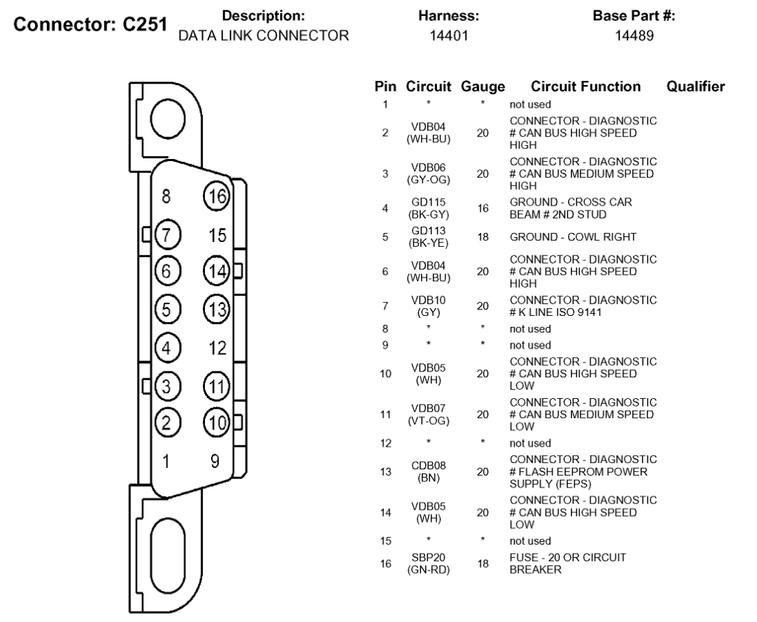
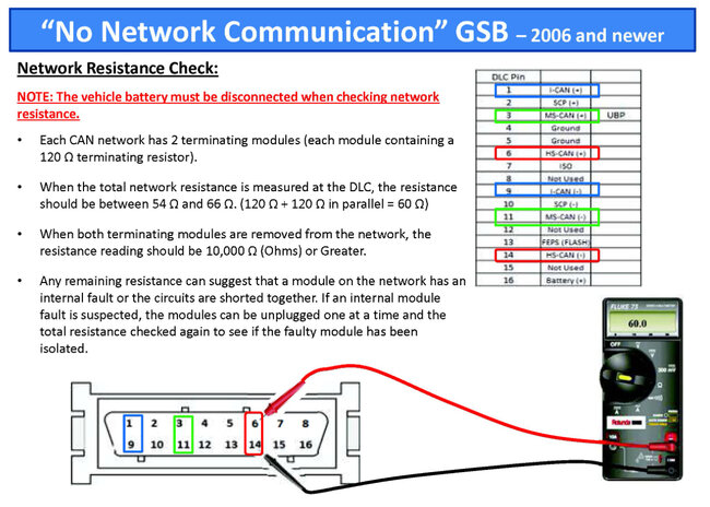
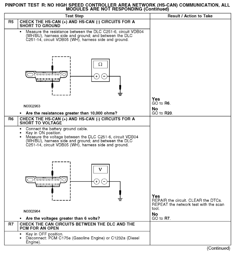
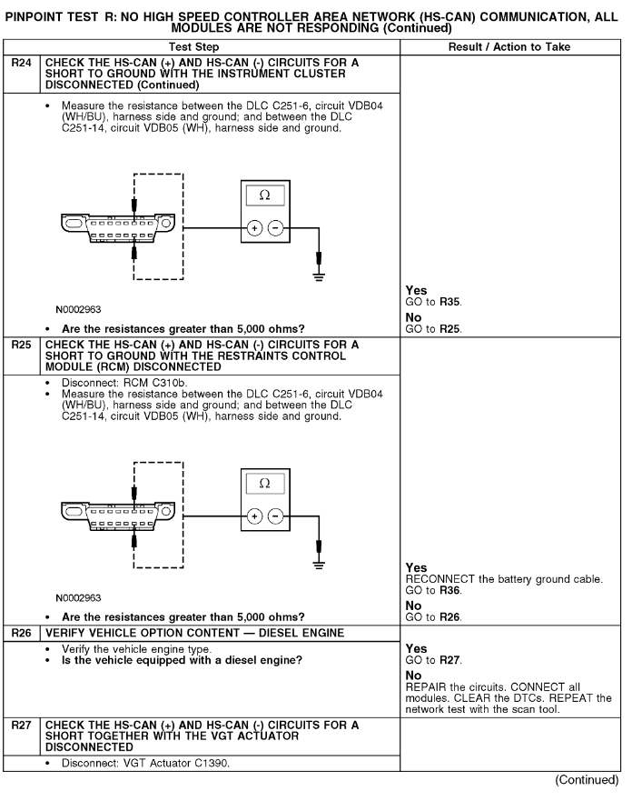
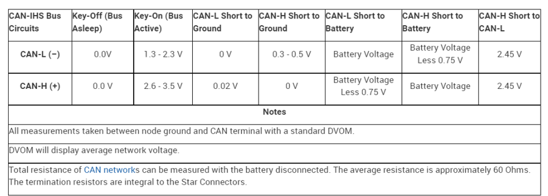
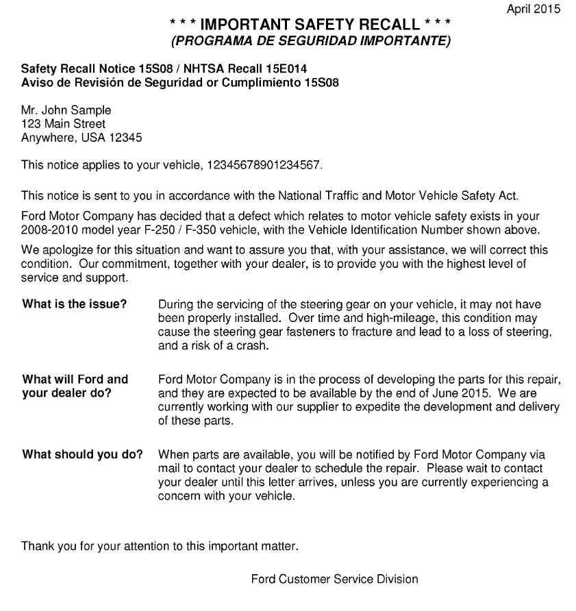
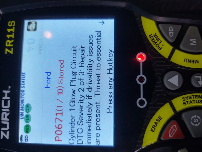
Honestly, I wish I could give you easier tests to do. I know the flow chart is a ton of steps and it can be easy to lose your place. But knowing that you are reading barely any voltage at all, I think maybe unhooking the battery negative, give it 10-15 minutes and then see what the resistance reading to ground is on pin 14 and 6. Using the battery negative cable for your ground instead of pin 4 or 5. And see what you get before you start on the flow chart. One other thing I was wondering, what were the readings on each pin 14 and then pin 6.

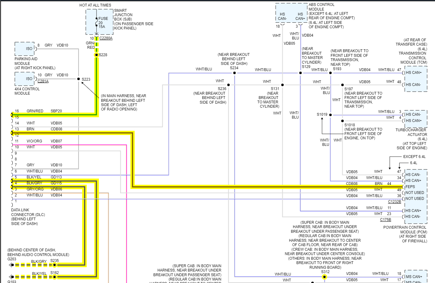
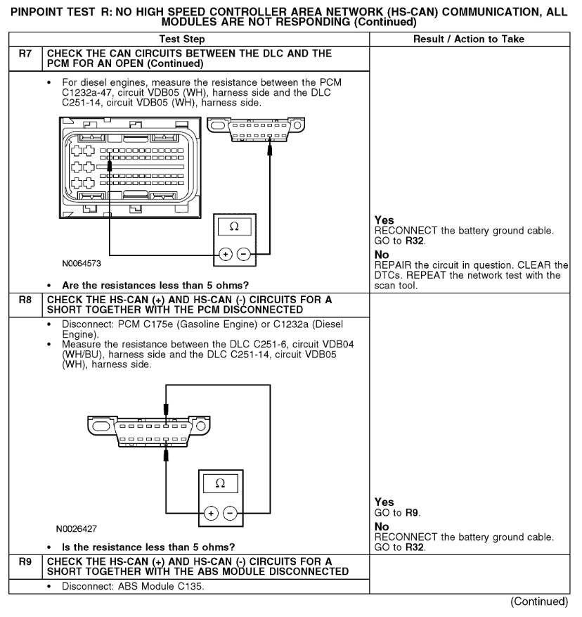
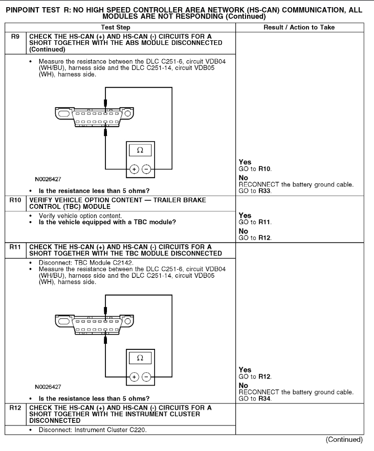
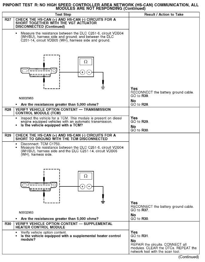
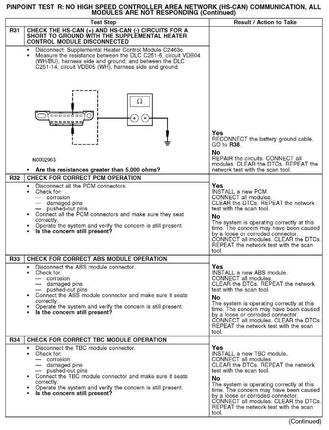
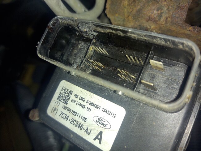
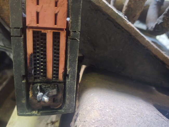
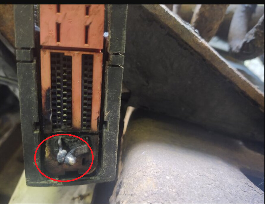
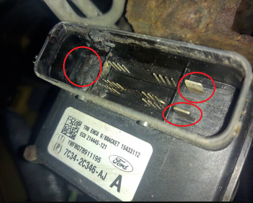
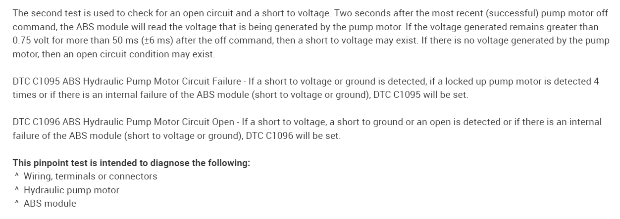
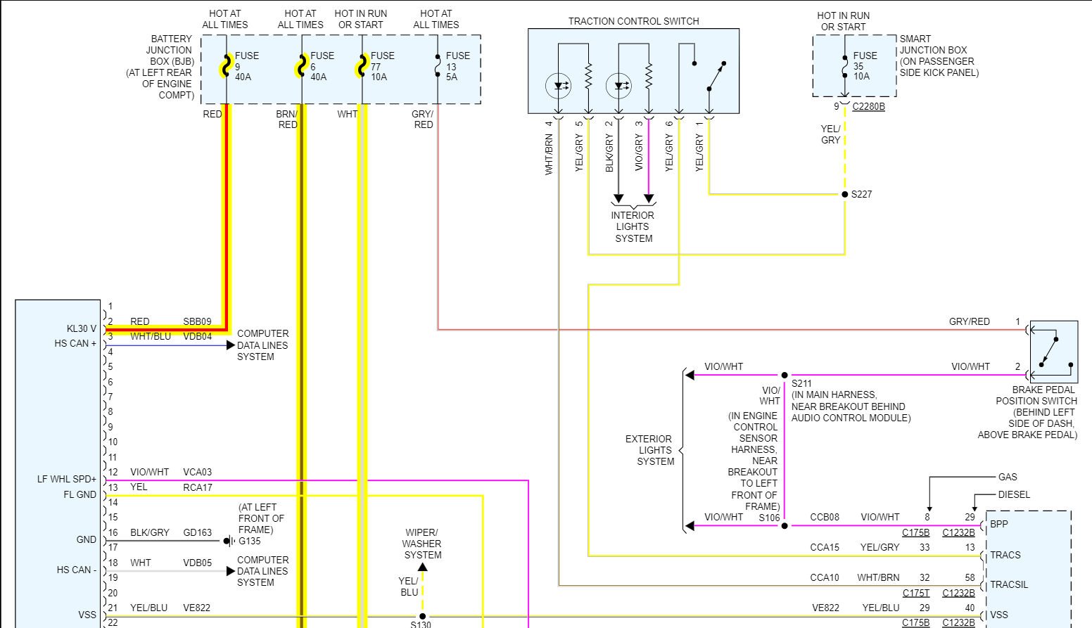
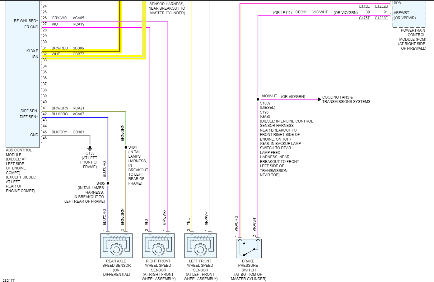
The reason I ask is if the Can High line is the one shorted to ground, pin 6 will read 0volts and pin 14 which is the Can Low line of this 2-wire network will read something a little bit higher, not much but it will be 0.3 to 0.5 volts because of the Terminating resistor in the circuit. If it's the opposite, pin 14 Can Low is shorted to ground, it will be reading 0volts and pin 6 Can High will read about 0.2volts. If we can determine which of the two wires is the actual shorted one, we can start following that wire. There are some splices and I'll post the diagrams showing you what I mean, and possibly find if this is a shorted wire, or if it's a module that has a short in it. Some modules we can get to easily enough such as the ABS module, the Turbocharger actuator, the PCM, we can unplug and see if the short disappears.

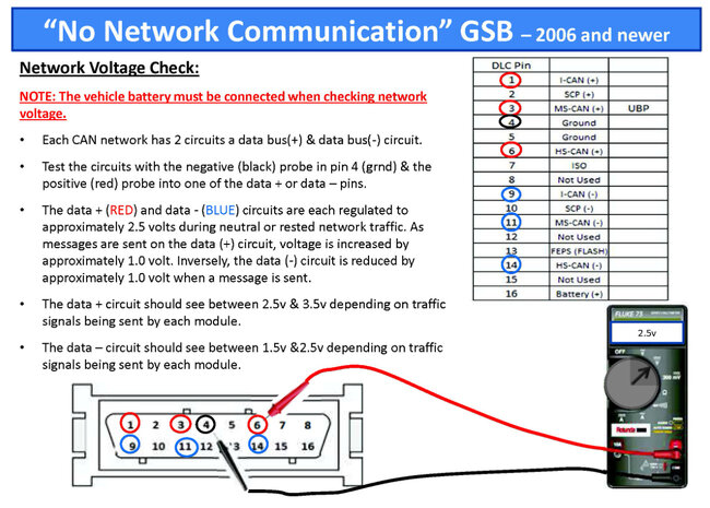
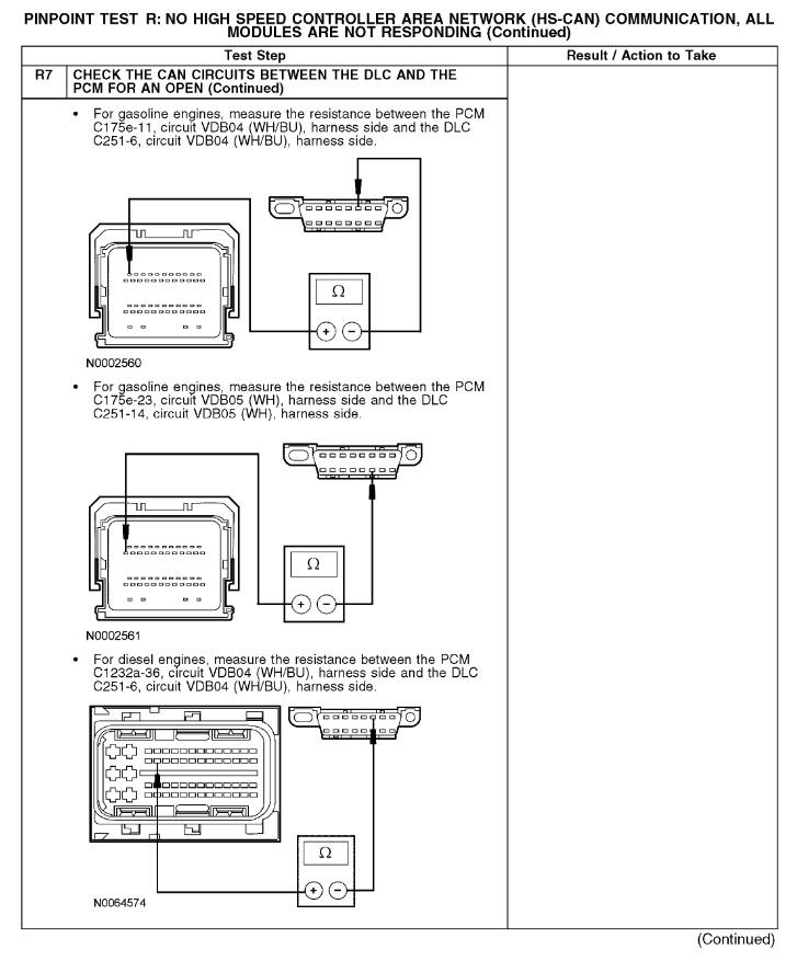
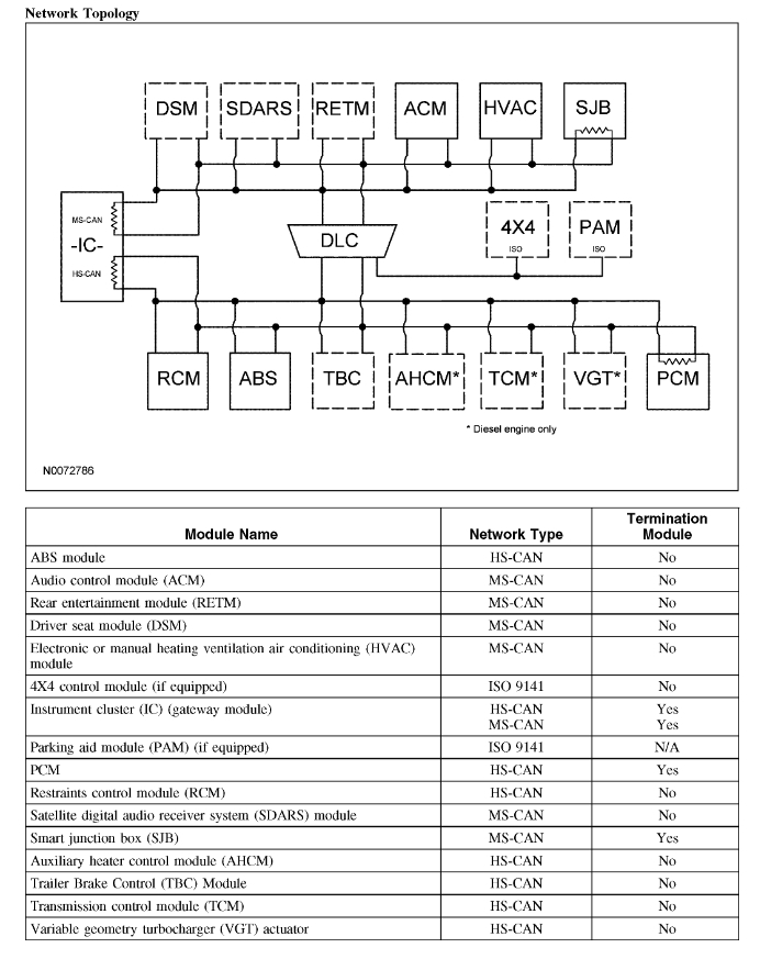
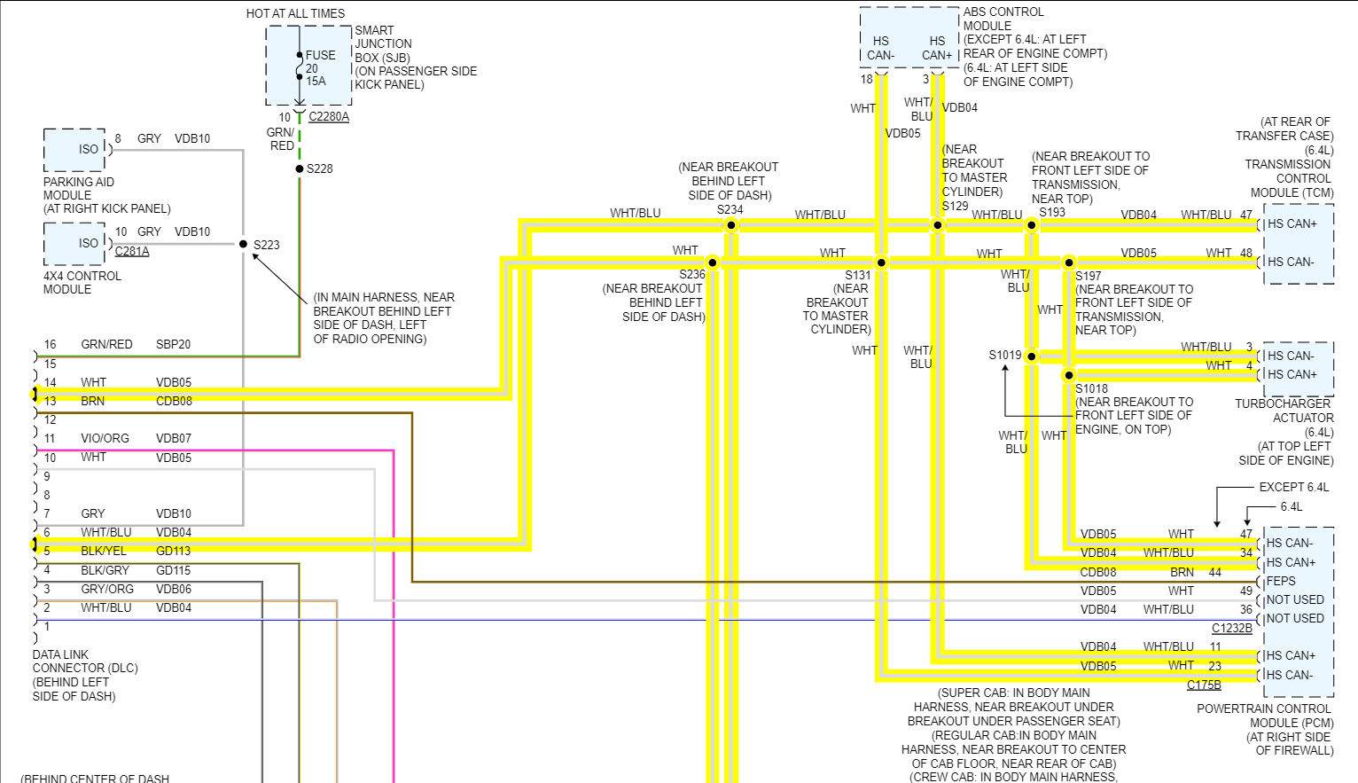
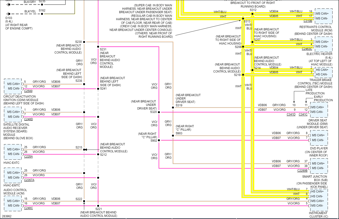
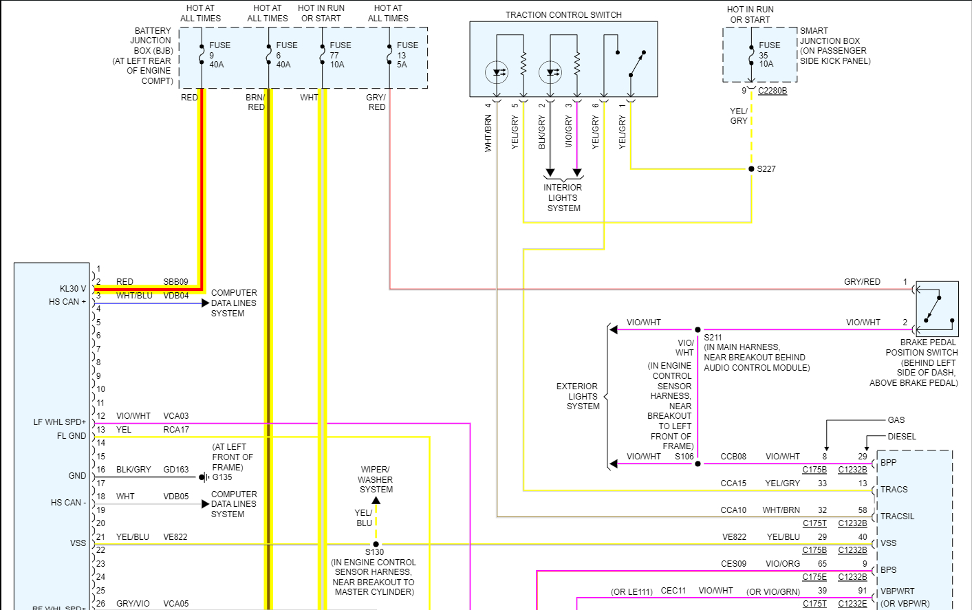
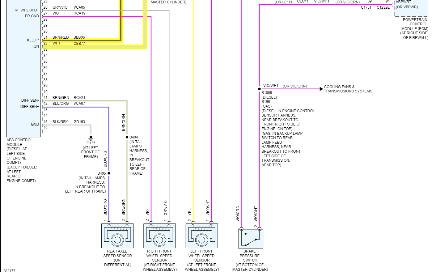
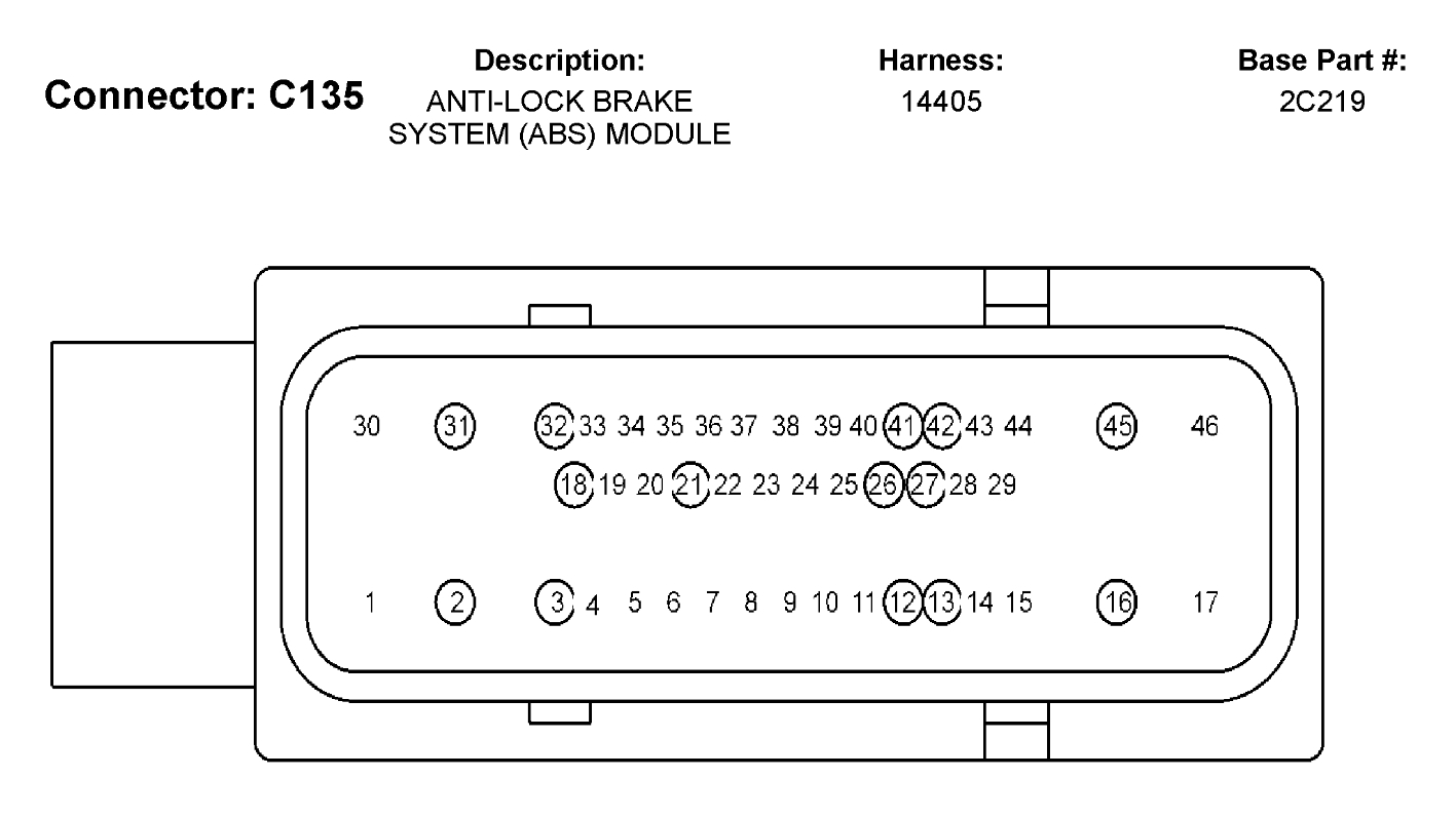
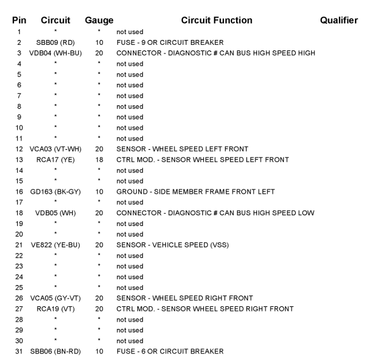
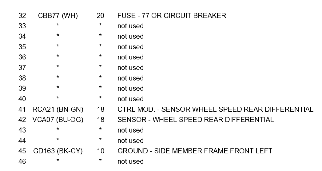
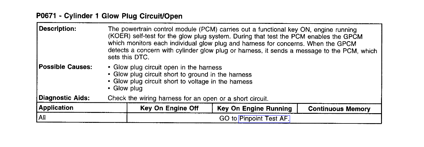
And if we can't get anywhere with that, then you can start going through the flow chart. The diagrams 2 and 3 below are the high speed can come from the DLC you can see on the left of diagram 2. Pins 11 and 2 are the Medium Speed can bus, so it appears that it's only the High speed that is down. You were not able to communicate with the ABS module either I assume. So, we can try that if you want, those two network wires are the same color throughout the entire truck.
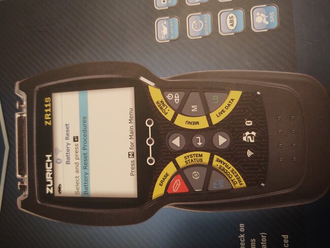
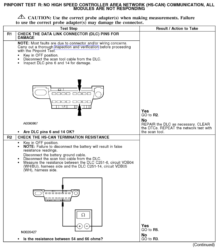
When you check at the data link connector, back probe the connector if you can so the pins don't get spread, since you'll have to have a meter lead hooked up to it for a while, unless we back probe the PCM connector. But start with getting a voltage reading for each pin and then disconnect the negative battery cable off and do a resistance test on pins 14 and 6 to ground. Maybe we can make this a little easier on you.
Was this
answer
helpful?
Yes
No
Saturday, October 8th, 2022 AT 6:37 PM
Tiny
HILLY59
  • MEMBER
  • 23 POSTS
The ABS light started the whole shooting match, it was the first warning light. I replaced all the sensors, even the one in the rear end, so we might get lucky. I will keep you posted. And once again, thank you.
Was this
answer
helpful?
Yes
No
Saturday, October 8th, 2022 AT 7:14 PM
Tiny
AL514
  • MECHANIC
  • 4,120 POSTS
Try unplugging the ABS module with the key off, then try your scan tool with the ABS module unplugged and see if you can communicate with the PCM.
Was this
answer
helpful?
Yes
No
Saturday, October 8th, 2022 AT 9:13 PM
Tiny
HILLY59
  • MEMBER
  • 23 POSTS
Will do.
Was this
answer
helpful?
Yes
No
Saturday, October 8th, 2022 AT 9:22 PM
Tiny
HILLY59
  • MEMBER
  • 23 POSTS
Thank you so much, the ABS module is fried, I unplugged it and was able to link to the computer, I will start by replacing that and go from there.
Was this
answer
helpful?
Yes
No
Sunday, October 9th, 2022 AT 11:47 AM
Tiny
AL514
  • MECHANIC
  • 4,120 POSTS
Oh my gosh, that thing is literally fried. I don't know what is it with Fords ABS modules, they seem to be the first to go. But glad you found the issue. I don't see any programming information. Looks like you can just replace the module section apart from the hydraulic unit. That was probably where the two network wires were shorted to the ABS modules case. Plus, the thing looked like it was about to catch fire.
Was this
answer
helpful?
Yes
No
Sunday, October 9th, 2022 AT 2:45 PM
Tiny
HILLY59
  • MEMBER
  • 23 POSTS
It was pretty close to it, when I pulled it apart, it was still smoking.
Was this
answer
helpful?
Yes
No
Sunday, October 9th, 2022 AT 5:07 PM
Tiny
AL514
  • MECHANIC
  • 4,120 POSTS
Wow, I've never seen an ABS module burn up like that. A first for me, but I've learned over 20 years that anything and everything can happen with vehicles. If it were that bad, I would really consider possibly changing the ABS module connector, The pins have been greatly overheated as well as the connector itself. I can see in the picture those larger pins are for higher current flow for the ABS solenoids in the hydraulic section of the module. Those pins are cooked, and that connector is no good either. I'm really surprised this didn't blow a fuse, it should have. I'll take another look at the ABS wiring diagrams and see why it didn't pop a fuse. It looks like there may have been a water intrusion issue there.

Okay, some service info is saying the hydraulic pump and the module are all one unit and some other info is saying the module (the electronic section) and the hydraulic unit can be replaced separately. So, obviously that information is useless. I just don't want to see you replace the computer just to have it turn out to be a shorted-out ABS pump. There are a couple of different codes it would have set for a shorted pump

You don't happen to remember the original codes you were getting before all this started do you? Were they just wheel speed sensor codes? Because the info here is saying the module runs self-tests on the pump to determine its condition and with this type of failure it should have disabled the ABS, the large pins also look like large ground pins that melted. The third diagram below are the codes for a failed pump. And of course, there is a flow chart for checking the pump which we can't do because of the connector and module failure right now.
Was this
answer
helpful?
Yes
No
Sunday, October 9th, 2022 AT 5:29 PM
Tiny
HILLY59
  • MEMBER
  • 23 POSTS
I am replacing the connector along with the module, it's pretty fried also. I truly appreciate all the help.
Was this
answer
helpful?
Yes
No
Sunday, October 9th, 2022 AT 5:45 PM

Please login or register to post a reply.

Sponsored links