Good morning,
Yes, it must be removed in order for the housing to be removed to access the heater core itself.
https://www.2carpros.com/articles/how-a-car-heater-works
https://www.2carpros.com/articles/car-heater-not-working
Roy
The instrument panel must be removed in order to remove the Housing Assembly HVAC. See: Instrument Cluster / Carrier > Service and Repair
WARNING: THE R-134a REFRIGERANT SYSTEM MUST BE RECOVERED BEFORE SERVICING ANY PART OF THE REFRIGERANT SYSTEM.
REMOVAL
1. Using a refrigerant recovery machine, remove the refrigerant from the A/C system, if equipped.
2. Remove instrument panel from vehicle. Refer to: Body and Frame, Interior Trim, Dashboard/Instrument Panel, Service and Repair, Instrument Panel Service Procedures, Instrument Panel Assembly Replacement, See: Dashboard / Instrument Panel > Removal and Replacement > Instrument Panel Assembly
3. Drain cooling system and remove heater hoses at the dash panel. Place plugs in the heater core outlets to prevent coolant spillage during unit housing removal.
4. Unfasten coolant recovery container and set aside.
5. Remove suction line at expansion valve. Cap open refrigerant lines to prevent moisture and/or dirt from entering.
6. Remove expansion valve from evaporator, and cap fittings.
7. Remove rubber drain tube extension from condensation drain tube.
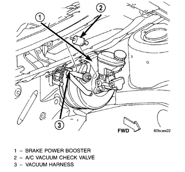
HVAC Vacuum Harness
imageOpen In New TabZoom/Print
8. Disconnect the vacuum harness at the power brake booster.
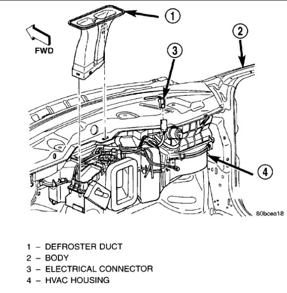
HVAC Housing Defroster Duct
imageOpen In New TabZoom/Print
9. Unsnap and remove the defroster duct.
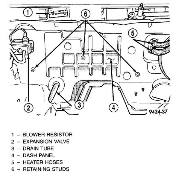
Dash Panel Retaining Studs
imageOpen In New TabZoom/Print
10. Remove three retaining nuts located in the engine compartment, on the dash panel.
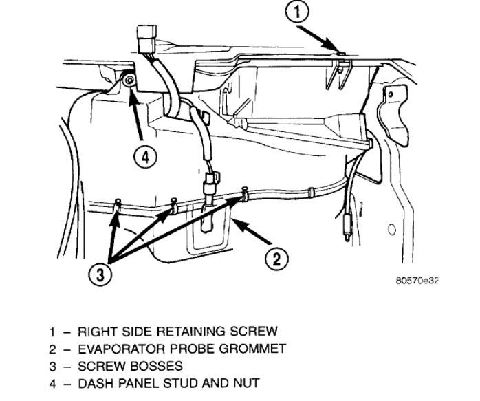
Housing Screws
imageOpen In New TabZoom/Print
11. Remove the right side retaining screw.
12. Remove remaining nut located on dash panel stud.
13. Disconnect the wiring connectors.
14. Remove assembly from the vehicle.
INSTALLATION
For installation, reverse the above procedures.
INSTRUMENT PANEL ASSEMBLY
DESCRIPTION
The purpose of the dash gauges and indicator lamps is to keep the driver informed about the operating condition of the vehicle. If an abnormal condition occurs, the driver is informed by indicator lamp. The driver can seek service before damage occurs.
Indicator lamps use ON/OFF switch functions for operation, while gauges use a sending unit or sensor.
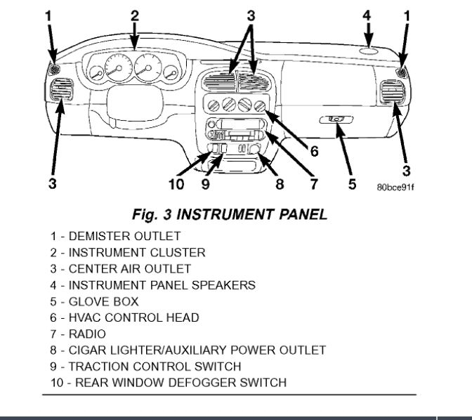
Fig. 3
imageOpen In New TabZoom/Print
The Instrument Panel (Fig. 3) can be removed as an assembly after a few part are removed to allow access to the retaining bolts. There is one self-aligning bulkhead connector on the left underside of the instrument panel replacing most of the main harness connectors. Once removed, the instrument panel can be serviced for replacement. Most of the parts of the instrument panel can be replaced individually without removing the complete instrument panel assembly.
REMOVAL
1. Disconnect and isolate the battery negative cable.
2. Push seats back to their full back position.
3. Using a trim stick (special tool #C-4755) or equivalent, gently pry out on left and right A-pillar trim moldings and remove.
4. Remove the instrument panel top cover.
5. Gently pull up on cluster bezel and remove from vehicle.
6. Remove two screws. Then gently pull rearward on left lower instrument panel cover and remove from vehicle.
CAUTION: Lock the steering wheel in the straight ahead position. This will prevent clock spring damage when the steering wheel rotates freely.
7. Remove steering column.
8. Remove left and right instrument panel end covers.
9. Remove left and right cowl side panels.
10. Remove center console.
11. Depress the sides of the Data Link Connector (DLC) and remove from instrument panel reinforcement.
12. Remove two center support mounting bolts.
13. Remove left and right A-pillar mounting bolts, two on each side.
14. Disconnect right side antenna connector.
Fig. 4
imageOpen In New TabZoom/Print
15. Remove left and right A-pillar door harness connectors (Fig. 4).
Fig. 5
imageOpen In New TabZoom/Print
16. Disconnect two harness connectors to HVAC at right top instrument panel (Fig. 5).
17. Disconnect one left side harness connector at top left of instrument panel for vanity and rear view mirrors.
18. Pull off the HVAC control head knobs.
19. Remove both A/C outlet barrels.
20. Remove two screws retaining the top front of the center bezel.
21. Using a trim stick or equivalent, gently pry out on the instrument panel center bezel and remove.
22. Remove the two retaining screws to the HVAC control head.
23. Disconnect the one instrument panel wire harness connector.
24. Disconnect the one vacuum harness connector.
Fig. 6
imageOpen In New TabZoom/Print
25. Pull HVAC control head out of instrument panel, twist 90 degrees and push back through the opening (Fig. 6). Do not disconnect the control cables.
26. Disconnect the center console wiring:
Airbag Control Module (ACM)
Parking Brake Warning Lamp Switch
Transmission Range Indicator Lamp
Shift Interlock Cable (ATX)
27. With help from an assistant, remove two bolts on top of the brake pedal support bracket. Pull rearward on instrument panel assembly and remove from vehicle.
Images (Click to enlarge)
Jan 5, 2021 at 4:03 AM