Welcome back:
Okay, you should have seen spark. Before we condemn the ECM, here is a flow chart for checking the ECM. It explains what to check for from the ECM side as well. Based on what you have done, I feel confident you can do this. However, if you need help, let me know.
________________________________
2008 Saturn Astra L4-1.8L
Electronic Ignition (EI) System Diagnosis
Vehicle Powertrain Management Computers and Control Systems Testing and Inspection Component Tests and General Diagnostics Electronic Ignition (EI) System Diagnosis
ELECTRONIC IGNITION (EI) SYSTEM DIAGNOSIS
Electronic Ignition (EI) System Diagnosis
Diagnostic Instructions
* Perform the Diagnostic System Check - Vehicle (See: Vehicle > Initial Inspection and Diagnostic Overview) prior to using this diagnostic procedure.
* Review Strategy Based Diagnosis (See: Vehicle > Initial Inspection and Diagnostic Overview) for an overview of the diagnostic approach.
* Diagnostic Procedure Instructions (See: Vehicle > Initial Inspection and Diagnostic Overview) provides an overview of each diagnostic category.
Circuit/System Description
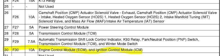
The ignition system consists of one integrated and sealed ignition coil/module assembly for the 4 cylinders. The engine control module (ECM) controls the individual coils by transmitting timing pulses on the ignition control (IC) circuit of each ignition coil to enable a spark event. When the engine is running the ECM monitors each IC circuit for improper voltage levels. The ignition coil/module assembly has the following circuits:
* An ignition voltage circuit
* A ground
* An IC circuit for each coil
Diagnostic Aids
* A slight to moderate resistance in the ignition voltage circuit, can cause a misfire condition or a crank/no start concern.
* Extended engine cranking time, will foul the spark plugs with excessive fuel and cause a crank/no start condition.
* A slight to moderate resistance on any IC circuit can cause a misfire.
Reference Information
Schematic Reference
Engine Controls Schematics (See: Powertrain Management > Electrical)
Connector End View Reference
Component Connector End Views (See: Vehicle > Connector Views)
Electrical Information Reference
* Circuit Testing (See: Vehicle > Component Tests and General Diagnostics)
* Connector Repairs (See: Vehicle > Component Tests and General Diagnostics)
* Testing for Intermittent Conditions and Poor Connections (See: Vehicle > Component Tests and General Diagnostics)
* Wiring Repairs (See: Vehicle > Component Tests and General Diagnostics)
DTC Type Reference
Powertrain Diagnostic Trouble Code (DTC) Type Definitions (See: A L L Diagnostic Trouble Codes ( DTC ) > Diagnostic Trouble Code Descriptions)
Scan Tool Reference
Control Module References (See: Vehicle > Programming and Relearning) for scan tool information.
Circuit/System Verification
Important: Verify that the engine is in good mechanical condition before continuing with this diagnostic.
Verify the following conditions:
* The ignition coil/module assembly is correctly connected.
* The proper spark plug type.
* The proper spark plug gap and torque.
Refer to Ignition System Specifications (See: Ignition System > Mechanical) and Spark Plug Inspection (See: Spark Plug > Component Tests and General Diagnostics) .
Circuit/System Testing
1. Ignition OFF, disconnect the harness connector at the ignition coil/module assembly.
2. Ignition OFF for 90 seconds, test for less than 5.0 ohms between the ground circuit terminal 1 and ground.
If greater than the specified range, test the ground circuit for an open/high resistance.
Important: If the ignition fuse is open, it will be necessary to test the spliced ignition circuits and the components for a short to ground.
3. Ignition ON, verify that a test lamp illuminates between the ignition circuit terminal 2 and ground.
If the test lamp does not illuminate, test the ignition circuit for a short to ground or an open/high resistance.
4. Ignition ON, verify that a test lamp does not illuminate between B+ and the affected IC circuit terminal listed below:
* IC 1 circuit: terminal 6
* IC 2 circuit: terminal 5
* IC 3 circuit: terminal 4
* IC 4 circuit: terminal 3
If the test lamp illuminates, test the IC circuit for a short to ground. If the circuit tests normal, replace the ECM.
5. Ignition OFF for 90 seconds, disconnect the ECM.
6. Test each IC circuit for less than 5.0 ohms between the ignition coil/module assembly harness connector and the ECM harness connector:
IC 1 circuit: terminal 6 and ECM connector X1, terminal 1 and X1, terminal 2.
IC 2 circuit: terminal 5 and ECM connector X1, terminal 17 and X1, terminal 18.
IC 3 circuit: terminal 4 and ECM connector X1, terminal 33 and X1, terminal 34.
IC 4 circuit: terminal 3 and ECM connector X1, terminal 49 and X1, terminal 50.
7. If the circuits test normal, replace the ignition coil/module assembly.
Repair Instructions
Ignition Coil Replacement (See: Ignition Coil > Removal and Replacement)
Control Module References (See: Vehicle > Programming and Relearning) for ECM replacement, setup, and programming
Repair Verification
If the customer concern was a flashing MIL, perform the following procedure:
1. Install any components that have been removed or replaced during diagnosis.
2. Perform any adjustments, programming or setup procedures that are required when a component is removed or replaced.
3. Clear the DTCs.
4. Turn OFF the ignition for 60 seconds.
5. If the repair was related to a DTC, duplicate the Conditions for Running the DTC and use the Freeze Frame/Failure Records, if applicable, in order to verify the DTC does not reset. If the DTC resets or another DTC is present, refer to the Diagnostic Trouble Code (DTC) List - Vehicle (See: A L L Diagnostic Trouble Codes ( DTC ) > Diagnostic Trouble Code Descriptions) and perform the appropriate diagnostic procedure.
6. To verify that the performance of the catalytic converter has not been affected by the condition that set this DTC, perform the Repair Verification for DTC P0420. Refer to DTC P0420 (See: A L L Diagnostic Trouble Codes ( DTC ) > P Code Charts > P0420) .
____________________________________________________
Let me know if this helps.
Joe
Sep 24, 2019 at 5:42 PM