Where is the A/C clutch relay located?

Tiny
DAVE FONZA
  • MEMBER
  • 1992 PLYMOUTH VOYAGER
  • 2.5L
  • 4 CYL
  • 2WD
  • 106,816 MILES
I'm trying to locate the relay for the air conditioning magnetic clutch. I am trying to jump wire the relay to get the clutch to engage or just replace the relay out right. A book I have shows a PIC of 5 relays on the driver's side inner fender. Mine only has 4. I bought a relay and tried to replace the new one with any of the 4 I have but it doesn't fit any of the harness plug-ins. So, I basically need to know exactly where the relay is located!
Sunday, November 13th, 2022 AT 1:29 PM

23 Replies

Tiny
CARADIODOC
  • MECHANIC
  • 33,754 POSTS
Here's two drawings that show it by the right front strut tower.

Have you checked the system pressures? If the refrigerant has leaked out, as it will over time, the low pressure cutout switch prevents the compressor clutch from engaging. That's done because then it would be possible to pump the low side into a vacuum. If there's a leak, that can draw in outside air along with the extremely harmful humidity with it. Moisture in the system can freeze and block the tiny orifice the refrigerant is controlled with, and it will lead to corroded parts.

Check out these related articles:

https://www.2carpros.com/articles/how-a-car-air-conditioner-works

https://www.2carpros.com/articles/air-conditioner-how-to-add-freon

They're recharging a newer system here with a different refrigerant. '93 and older models use R-12 unless your system has been retrofitted to use the newer R-134. The two refrigerants and the oils they use in their systems are not compatible, so don't mix them or add the wrong type.

Also be aware refrigerant is extremely dangerous to work with. Professionals wear gloves, safety glasses, and a face shield. Escaping refrigerant can cause frostbite and blindness.

also check out these articles:

https://www.2carpros.com/articles/re-charge-an-air-conditioner-system

https://www.2carpros.com/articles/car-air-conditioner-not-working-or-is-weak

If your system is totally out of refrigerant, it should be pumped into a vacuum for at least a half hour before recharging it. Once that is done, sometimes you do have to bypass the clutch relay to get the compressor to start drawing in the new refrigerant. The easiest way to do that is to unplug the low pressure cutout switch, then use a cotter pin or stretched-out paper clip to jump the two terminals in the plug.

If there's still some pressure in the system, you can add just enough refringent to fill it, but over-charging it can be much worse than having it under-charged. Chrysler used a sight glass to tell when the system is fully charged. You may need to remove the jack, then there's a small hole in the top of the inner fender where you can look through to see the sight glass on top of the receiver / drier. Add refrigerant with the compressor running just until you no longer see vapor bubbles flowing through that window.

(For our friends with older Fords that used a sight glass, this doesn't apply. There will always be vapor bubbles, even when the system is over-charged). For those and all other models without a sight glass, the only way to know how much the system is charged is to recover any that's still in there, then pump in the measured amount called for.

Let me know if this solves your problem, and how you make out.
Was this
answer
helpful?
Yes
No
Sunday, November 13th, 2022 AT 3:05 PM
Tiny
DAVE FONZA
  • MEMBER
  • 12 POSTS
Still having the same problem even after I located the correct relay. When I jumper wired that to make the clutch engage, the cooling fan came on. So, I still need help figuring out what to do to get the clutch fan to come on. I've tried the 2 on the passenger side engine compartment and jumping either of them causes the cooling fan to come on. So, please help.
Was this
answer
helpful?
Yes
No
Tuesday, November 22nd, 2022 AT 11:57 PM
Tiny
CARADIODOC
  • MECHANIC
  • 33,754 POSTS
I still don't know if there's any refrigerant in the system. If there is not, or it's real low, the low-pressure cutout switch will prevent the compressor clutch from engaging. A fast way to identify that is to bypass that cutout switch. I'm sorry the diagrams didn't show up in my first reply. I must have forgotten to upload them for you.

These diagrams cover the heating and AC system without a rear heater. The blue arrow in the first diagram is pointing to the switch on the "H-valve" assembly. That's an aluminum block bolted to the center of the firewall, right above the engine, and it has two aluminum pipes attached to it. Look for that two-wire switch. Unplug it, then use a stretched-out paper clip or cotter pin to connect the two terminals in the plug while the engine is running and the AC is selected or the heater is set to "defrost". If the compressor engages, the system is low and must be recharged.

If the clutch doesn't engage, put your fingers on the AC clutch relay and feel if it clicks when you put the jumper in and out. If the relay clicks, we'll have to look at the fuse link wire and rest of the circuit for the clutch coil. If the relay doesn't click, we'll have to look at the control system including the Engine Computer.

Note the second diagram lists the AC clutch relay as being on the left inner fender, but the last drawing shows it over the passenger side strut tower. Only one of those can be right.

I'll be out of town tomorrow. Will check in as soon as I get back to see how you're doing. Let me know what you find up to this point.
Was this
answer
helpful?
Yes
No
+1
Thursday, November 24th, 2022 AT 4:57 PM
Tiny
DAVE FONZA
  • MEMBER
  • 12 POSTS
Where did you find these pictures from? I wish I had the book they are so accurate!
Was this
answer
helpful?
Yes
No
Saturday, November 26th, 2022 AT 9:45 AM
Tiny
DAVE FONZA
  • MEMBER
  • 12 POSTS
So, I did that today. Nice day out whopping 50 degrees! I removed the boot that connects the two terminal low-pressure sensor. Nothing happened. So, while that was jumper-ed I also jumper-ed the harness plug in for the magnetic clutch. The cooling fan came on, but no clutch engaged. So, your next step mentioned something about checking the fuse link. I'm all ears. Let me know how to do this please. Thanks, David
Was this
answer
helpful?
Yes
No
Saturday, November 26th, 2022 AT 2:06 PM
Tiny
CARADIODOC
  • MECHANIC
  • 33,754 POSTS
These diagrams are from AllData, an online service manual provider. Independent repair shops pay over $1000.00 per year for access to the site. You can purchase a subscription for just one model. Last time I checked, it cost around $27.00 for one year and around $45.00 for five years. In this case, these diagrams are photocopies right out of the paper Chrysler service manual. In later years AllData only offers their version of diagrams that are not very easy to follow and they reproduce very poorly for posting here. I have always preferred paper manuals because I can put bookmarks in them, write notes, and have multiple pages open at once. I have hundreds of Chrysler manuals from auctions and one of their training centers that closed. You can find them on eBay too for a reasonable cost. Back in the '90s they cost $93.00 per set of books, and $53.00 per set when they were five or more years old. Because I'm used to them, I find the diagrams very easy to follow, but most people do not. I can help you follow them and I can explain what all the symbols and "page numbers" mean.

The first thing we need to do is feel if the compressor clutch relay is clicking. I'm still confused by finding drawings that show that relay in two different places. I have four of these at home, two older and two newer. The closest is a '94 model. It doesn't pay to look at that one as a lot had changed from a 1992 model.

We may need to approach this from a different direction. Look for the relay on the right inner fender as shown in the sixth drawing above. It's by the right strut tower. When I'm trying to verify I found the right relay, I go by the wire colors. There's always enough difference that two or more won't be confused with each other. Under the socket you should see a dark blue / black 12 gauge wire. It's listed on the diagram as "C3 12DB / BK". That's circuit C3 to just show it's different than all others, it's a 12 gauge wire, and it's dark blue with a black stripe, or "tracer". There will also be a gray wire and a dark green wire, both also 12 gauge. The last one will be a very thin 20 gauge wire, dark blue / orange. If you see those four wires under the relay socket, you have the right relay.

For these voltage readings, an inexpensive test light can be more accurate under some conditions than a digital voltmeter, but you can use either. I can explain that more once we have this problem solved. When you take readings in the relay socket, (or fuse sockets), be careful to just touch the terminals. If you stick the test probe into the terminals, you run the risk of spreading them resulting in weak or intermittent connections in the future.

If you need help with using the test light or voltmeter, look at these articles first:

https://www.2carpros.com/articles/how-to-use-a-test-light-circuit-tester

https://www.2carpros.com/articles/how-to-use-a-voltmeter

They're using an auto-ranging voltmeter here. That's an expensive feature you don't have to have. You can find a perfectly fine voltmeter at Harbor Freight Tools for around $7.00, and a test light for less. These are also found at Walmart, any hardware store, and any auto parts store. I can help with setting up the meter is needed.

If you look at the very bottom, center of the second diagram up above, you'll see "to charging system". The charging system has nothing to do with the operation of the AC system. That is just where the wire in question originates. Just to the left, that wire is listed as "A16 12GY". "A" wires always originate at the battery's positive post or right after a fuse that's connected to that post. There will not be any type of switch in between, so we know there should be full battery voltage on that wire all the time. No need to turn on the ignition switch. Just to the right of the relay, and my red arrow, they show the relay's terminals in a dashed box. Those CAN be hard to follow because some engineer drew them exactly as they look in the actual socket. It would be easier if they just drew four straight lines, but no one ever asked for my opinion. To make this process faster, just touch your meter or test light probe to all four terminals, one at a time. You should find 12 volts on one of them. If you do not, we have to work back and find the fuse link wire. That will be in a bundle of similar dull-colored wires, (usually white, gray, orange, or green, in a harness running around the left front strut tower. Those are tested by tugging gently on them. If one is good, it will act like a wire. If one is burned open, it will act like a rubber band. I'll go deeper into details about them later too, if necessary.

For now, just let me know if you find 12 volts on that one wire. I have to run home to do some more typing.
Was this
answer
helpful?
Yes
No
Sunday, November 27th, 2022 AT 12:53 AM
Tiny
DAVE FONZA
  • MEMBER
  • 12 POSTS
So, I did that today. Nice day out whopping 50 degrees! I removed the boot that connects the two terminal low-pressure sensors. Nothing happened. So, while that was jumper-ed I also jumper-ed the harness plug in for the magnetic clutch. The cooling fan came on, but no clutch engaged. So, your next step mentioned something about checking the fuse link. I'm all ears. Let me know how to do this please. Thanks, David
Was this
answer
helpful?
Yes
No
Monday, November 28th, 2022 AT 9:19 AM
Tiny
DAVE FONZA
  • MEMBER
  • 12 POSTS
I did a voltage check on both relays above the strut tower a while back. I know which one is correct because I bought a new relay for the clutch. It would only fit into one of those two but there is power to both.
Was this
answer
helpful?
Yes
No
Monday, November 28th, 2022 AT 1:24 PM
Tiny
CARADIODOC
  • MECHANIC
  • 33,754 POSTS
Okay, since you know which is the correct relay, lets jump that and see if the clutch engages. You'll hear it click if it does. Use a piece of wire, a stretched-out paper clip, or a cotter pin. Find the terminals that correspond to the dark blue / black wire and the gray wire. Lightly touch the wire to those two terminals. The ignition switch doesn't have to be on.

If the clutch engages, that part of the circuit has to be okay, then we have to look at the control side of the relay to see why it isn't being energized. This is where the most common cause is low refrigerant. You jumped the two terminals in the low-pressure cutout switch and that didn't make the clutch engage, so we are likely looking for something else.

As long as the system is near fully-charged, most failures for this problem will be caused by the circuit you're about to jump because that's the high-current side. Parts have to be beefier, but they're more likely to fail.

One more comment of value. I know you found voltage at the relays, but if you have a fuse box just above the brake power booster, check the fuses in there. I have a '95 model that was missing the fuse box cover, then some of the fuses corroded to powder. There were multiple symptoms from just one of them. One was the "Air Bag" light turned on. That was the warning to tell that other systems were dead that you wouldn't notice until you needed them. This would something simple to not overlook. While my fuses were corroded off, the terminals in the box were fine.
Was this
answer
helpful?
Yes
No
Monday, November 28th, 2022 AT 10:15 PM
Tiny
DAVE FONZA
  • MEMBER
  • 12 POSTS
Okay I did that and there is no clutch engagement. Only the cooling fan comes on.
Was this
answer
helpful?
Yes
No
Tuesday, November 29th, 2022 AT 2:11 PM
Tiny
CARADIODOC
  • MECHANIC
  • 33,754 POSTS
I'm suspicious you're on the wrong relay. Look again at the colors of the wires you're jumping. That socket should have a gray wire and a black wire that you're jumping, both 12 gauge, rather fat. Also a 12 gauge dark green and a smaller 20 gauge dark blue with orange. If that is what you have, the next test is going to be down by the two-wire plug on the compressor.

If you find the wire colors are light green and gray, both 12 gauge, and dark blue and dark blue / pink, both 20 gauge, that is the radiator fan relay and would explain why the fan is running.

Assuming you're on the right relay, check for 12 volts on the dark blue / black wire at the compressor's plug. That's the blue arrow in the first diagram. If it is missing there when you jump the relay, we'll have to work back to the ten-pin plug, (double purple arrow in the second drawing.

Point of interest, when you see both halves of a connector, fold one over on the other to see where a wire comes in and goes out. Here, with one part over the other one, if you flip the top half over on top of the lower half, the two dark blue / black wires line up. Those are the two mating terminals in the connector for that circuit. Here the color stays the same even though the gauge changes. Those connectors are a real good place to find the cause of a problem. One or both terminals could be corroded, the female terminal could be spread open by being picked too hard with a test probe, or there can be corrosion between two or more adjacent terminals. Corrosion between terminals usually can't conduct enough current to cause a power circuit to operate, such as a fan motor, but they can easily cause tiny sensor signal circuits to interact and cause elusive problems.

Same when you see the two connector halves side by side. Fold one half over horizontally over the other half to follow a wire.

If you do get 12 volts on the dark blue / black wire, check next on the black wire, (black arrow). That must be done with the plug connected, otherwise the reading is meaningless. I like to unplug it, stick a paper clip in on the backside of the plug alongside the wire, plug it back in, then I have a wire sticking out suitable for connecting a clip lead to, then to my voltmeter probe. You should not find any voltage on that wire when you jump the relay. It's not uncommon for a digital voltmeter to pick up a few hundredths of a volt. Consider that to be 0 volts. If you find 12 volts on the dark blue / black wire and 0 volts on the black wire, the clutch should be engaging. Either the clutch coil is defective or one of the terminals in that plug is not making contact with its mate.

If you find some voltage on the black wire, the ground wire has a break in it, (green arrow). That ground is shared with the radiator fan motor. I don't see a path for current to flow if that ground is broken. This is what we refer to as "back-feeding". When you jump the relay, current flows through the compressor clutch coil, then can't find a path to ground, so it looks for an alternate path to continue on back to the battery. In this case that alternate path is through the radiator fan motor, but as I said, I don't see where it can continue after that. If I'm overlooking something, the clue would be the fan runs, as you've observed, but it will run slower than normal, ... And backward. When it runs, air should be blowing onto the engine. If it's running the wrong way, it will be pushing air out the grille.

Let me know what you find at the clutch coil terminals. I could spend all night typing a description of all the possibilities and still be wrong. Instead, I'll figure out where to go next once I know what you find.
Was this
answer
helpful?
Yes
No
Tuesday, November 29th, 2022 AT 7:20 PM
Tiny
DAVE FONZA
  • MEMBER
  • 12 POSTS
Okay, I will refer to these two relays as right and left.
The left has four wires - green - 12, white - 20, black - 20, and gray - 12
The right has four wires - blue - 12, green - 12, gray - 12, and blue w/pink stripe - 20
I am getting 12 volts for the left from the green wire and the right from the blue.
Both checked unplugged from relays. Nothing operates trying to jumper either one. I have to assume one of them needs to be plugged in so using the colors i've given, I need to know which one is for the clutch, and the cooling fan. The engine size is 2.5 l - 4-cylinder engine. I'll need to know which wires to jump for the clutch relay is figured out.
Was this
answer
helpful?
Yes
No
Friday, December 2nd, 2022 AT 3:05 PM
Tiny
CARADIODOC
  • MECHANIC
  • 33,754 POSTS
For the right relay, could that 20-gauge wire be blue / orange? The stripe colors often cause confusion. That's the compressor clutch relay. Double-check there's 12 volts on the gray wire. If there is not, we have to work back toward the fuse. If there is, jump that to the dark blue / black terminal. Those wires are for the two switching contacts in the relay. The clutch should click into engagement. Nothing else should turn on. If the clutch engages properly, we're done in the high-current half of the circuit, and we'll have to look next at the low-current side of that relay and the controls that run it.

The wire colors you listed for the left relay are on the lower right of this diagram. They're for the AC condenser fan motor, next to the radiator fan motor. If you were jumping this one previously, it would explain why a fan turned on.
Was this
answer
helpful?
Yes
No
Friday, December 2nd, 2022 AT 3:32 PM
Tiny
DAVE FONZA
  • MEMBER
  • 12 POSTS
It might be blue/orange. Colors have faded some after all the years so it could be. I get power from the gray 12 wire. My mistake.
Was this
answer
helpful?
Yes
No
Saturday, December 3rd, 2022 AT 12:59 PM
Tiny
CARADIODOC
  • MECHANIC
  • 33,754 POSTS
Please keep me updated on your progress. I'm here almost every day.
Was this
answer
helpful?
Yes
No
Saturday, December 3rd, 2022 AT 4:33 PM
Tiny
DAVE FONZA
  • MEMBER
  • 12 POSTS
So how do all the wire colors line up for you that I gave to you last? Are we going to decide that the right relay is for the clutch? Then I will need to know which wires to jump to try to engage the clutch. Do I reconnect the other relay first?
Was this
answer
helpful?
Yes
No
Sunday, December 4th, 2022 AT 11:03 AM
Tiny
CARADIODOC
  • MECHANIC
  • 33,754 POSTS
Sounds like it's the right relay we want. The red arrow is pointing to the two switching contacts. The terminal corresponding to the gray wire should have 12 volts on it. Jump that one to the terminal corresponding to the dark blue / black wire and the clutch should click.
Was this
answer
helpful?
Yes
No
Monday, December 5th, 2022 AT 4:26 PM
Tiny
DAVE FONZA
  • MEMBER
  • 12 POSTS
Success! Clutch engaged. Now I can make sure to add the right amount of Freon. My next move is to add enough until the pressure stabilizes. I have used 2 of the small cans since I began the effort of trying to jumper the clutch. Now that I have done that, while the clutch was engaged, the pressure on the high side went from 40 PSI to zero. Any idea how many small cans I will need to add so I don't have to jumper the clutch anymore? Then I can plug the relay back in to see if that's working as well as check for amount of oil in the system. I've got some of those plastic press thingy's that you squirt out Freon through one of the fittings that gives a color change, but, I need to circulate the Freon in the system first once I get that in full operating status. So, for now, how many cans?
Was this
answer
helpful?
Yes
No
Tuesday, December 6th, 2022 AT 1:21 PM
Tiny
CARADIODOC
  • MECHANIC
  • 33,754 POSTS
You have something else going on.

First, for the benefit of others researching this topic, allow me to remind you how dangerous it is to work with refrigerant. It can cause blindness and frostbite. Professionals always wear gloves, safety glasses, AND a face shield. Watch for the telltale mist around a leaking connection such as a charging hose. I like to twist a rag around hose connections because of the escaping refrigerant when disconnecting those hoses.

The next warning is for the benefit of the AC system. If it was opened to replace a part, or if it was totally empty for a period of time, the system must be pumped into a vacuum for at least 30 minutes before adding refrigerant. When air gets into the system, it's the humidity that comes along with it that will cause the damage and possible poor or intermittent cooling. The receiver / drier is also supposed to be replaced at the same time, but we don't always do that. The desiccant in it can hold roughly ten droplets of water. If any water circulates in the system, it leads to corrosion of metal parts, most often the evaporator and condenser. It will also freeze at the expansion valve causing blockage that stops the flow of refrigerant until it melts. Then it will circulate through the system until it freezes there again. Until it thaws and circulates again, cooling will be lost. That can last from a few minutes to perhaps a half hour or more. Pumping the system into a vacuum causes the water to boil at 77 degrees F. And turn into a vapor that can be pumped out.

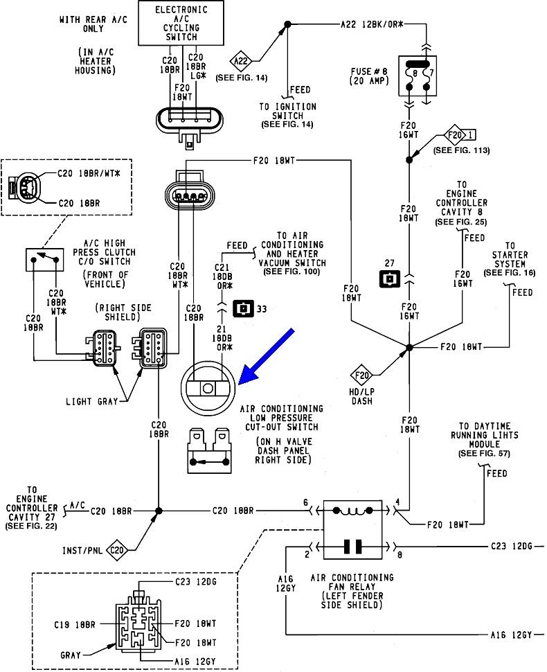
Once the system has been pumped into a vacuum, when refrigerant is added from a charging station, it expands as it warms up. That increased pressure turns on the low-pressure cut-off switch and allows the compressor clutch to be turned on by the control circuit.

When you're charging from the one-pound cans, the pressure should go high enough to also turn on that switch, however, the volume going in is rather low, so expect the compressor to quickly pump all that refrigerant into the high side, leaving the low side too low for a few seconds to keep the low-pressure cut-out switch engaged. The system will cycle on and off, with the "on-times" becoming longer and longer as the pressures build up.

As the low-side pressure increases, the rate of flow from the can will go down. Eventually the low side pressure will equal that in the can and all flow will stop. An easy trick to get the last 3/4 out of the can is to set it in a pot of hot water. It's not uncommon to totally empty the can that way in less than 30 seconds. The heat expands the refrigerant and raises its pressure well higher than that in the low side of the system. Always keep the top of the can up so only vapor goes into the charging hose, especially when using the hot water. Compressors can't pump or tolerate liquid refrigerant. If we're lucky, the compressor will just lock up and slip the drive belt until the refrigerant vaporizes. If we're not lucky, the compressor will be damaged.

For my next comment of value, '93 and older AC systems can be retrofitted to use the newer R-134 which is less expensive and easier to find. That was originally a rather expensive and complicated procedure. Different hoses were required with nylon liners because the R-134 molecules are smaller and will seep through the rubber hoses. The compressor was supposed to be replaced with one that develops about twice the high-side pressure to get the same efficiency. That meant replacing the evaporator and condenser with units that could withstand those higher pressures.

The good news is over time that got simplified to replacing the oil in the compressor with oil that is compatible with R-134, and installing non-removable charging fitting adapters that match R-134 equipment.

Okay, to continue, if you've already added two cans, the system might be seriously over-charged, or it has been leaking out somewhere. If your van has a rear heater and AC system, it calls for 45 ounces of refrigerant. If there's no rear unit, it calls for 34 ounces; just over two cans total.

Over-charging is more harmful than under-charging, both to the system and to efficiency. With the proper amount of refrigerant, the evaporator in the dash will have liquid in the bottom half and vapor in the top half. The point at which it changes state from liquid to vapor is the point at which it absorbs a real lot of heat and becomes cold. You want that point to be right in the middle of the fresh air flow coming in. When the system is over-charged, the evaporator is filled with liquid. It turns to a vapor in the hose under the hood going to the compressor. That's where it turns cold. It doesn't do any good turning cold under the hood. The other fear is that liquid could slosh into the compressor causing permanent damage to it.

Please let me add two more observations so I can get that over with. One is a neat fact about R-12. When it is at rest, meaning in a can or in the vehicle's system with the engine off, its pressure follows its temperature almost exactly. At 60 degrees, you'll find the pressure in the can and in the system is very close to 60 psi. Don't know if that applies to R-134 or R-22.

The second observation is if you start with that 60 psi in the system, then bleed some off, the pressure will drop. At a lower pressure, the refrigerant will boil, some will turn to a vapor which means it will expand a lot, and that makes the pressure go right back up to 60 psi. If you continue to bleed off, let's say half the refrigerant in the system, what's left will partially vaporize, expand, and the pressure goes right back to 60 psi. This fact can be summed up by, saying, "if there is even one drop of liquid refrigerant left in the system, the pressures on the gauges will very nearly equal the temperature". That means you can't tell how much charge is in the system by looking at a pair of gauges. Remember, that only applies to a system at rest. In that state the high and low sides need time to equalize.

Now is where the fun begins. I became confused when you started talking about gauges. Most charging from one-pound cans is done without any gauges or with a single gauge on the hose. If you have a gauge on the high side, you must be using a pair of gauges made for this purpose. Regardless, the pressure can't go from 40 psi to "0" when the compressor starts pumping. That's what could happen on the low side. If you're charging with a single hose from the can, that hose will only fit on the low-side fitting.

If you already have added two cans of refrigerant, and the low side is getting drawn down to 0 psi, or into a vacuum, that indicates there's a blockage in the system. Follow the hoses and look for a place where frost is forming. That will be the point where it's going from a higher pressure to a low pressure, and that will be the point of the blockage. If you see that on the expansion valve on the firewall, the system could be under-charged. The refrigerant is supposed to change to a low pressure there, but still be a liquid. It shouldn't turn to a vapor until it gets into the evaporator.

I never learned how to interpret gauge readings as well as the specialists seem to be able to do. The two sides will start to equalize when the compressor cycles off, then when it cycles on, the high side will go higher, and the low side will drop down. The systems are designed so the compressor will turn off when the low side drops to near 40 psi. This goes back to my comment about temperature closely equaling pressure. The biggest goal of AC systems is not to make the air cold; it's to remove the humidity. That occurs when the warm air passes through the cold evaporator in the dash. The humidity condenses and drops into a drain pan with a tube that exits under the passenger's foot area. If the system was allowed to get down to 32 psi / 32 degrees F, that "condensate" would freeze into a block of ice and block air flow. 40 psi is the pressure commonly used when designing AC systems for cars to prevent evaporator freeze-up.

Once you clarify what kind of gauge setup you're using, and where the hoses are connected, this finally brings me to the fun part. Given that you can bleed off a lot of refrigerant and the gauge pressures will still read the same, we know you can't tell the state of charge by looking at them. There's only two ways to know how much refrigerant is in the system. This first method applies to every vehicle. You have to completely recover / remove all the refrigerant, then pump in the measured amount called for. As a point of interest, that is not done by volume as it is with gas, oil, or transmission fluid. It is done by weight. Professional charging stations have their refrigerant cylinders sitting on a scale. They stop adding when the desired weight change takes place on that scale. For those of us using the little cans, we have to go by the weight stamped on the can, typically 14 ounces.

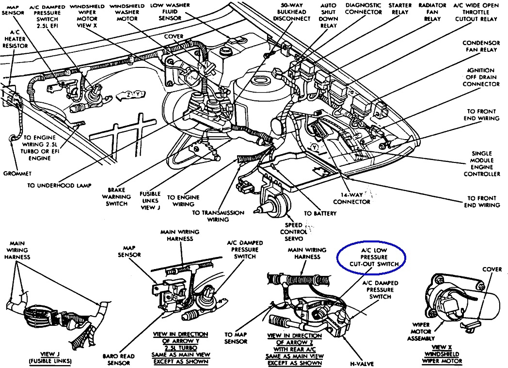
The second method only applies to Chrysler products, including your van. Chrysler provided a sight glass specifically for this purpose, and they're very accurate. The photo below shows what it looks like. My red arrows are pointing to that sight glass. You may need to remove or loosen the jack by the right hood hinge. I have four of these vans, so I'm doing this from memory. On two of them, the jack doesn't have to be moved. But you have to look through a small hole in the lip of the fender. The sight glass is right below that hole. With this, you don't have to know how much refrigerant was in the system when you started, and you don't have to know how much you're adding. You simply add until you no longer see vapor bubbles flowing through the glass window. If you start with the system completely empty, you'll start to see bubbles after adding as little as a quarter can. The bubbles will stop appearing each time the compressor cycles off. I've been known to add an additional two ounces for good measure, but remember, over-charging is more harmful than under-charging. That extra two ounces can destroy the compressor in a home refrigerator, but automotive systems go up and down over bumpy roads, so they're designed to tolerate a small over-charge.

I have to add a note here for our Ford friends. Ford added a sight glass as far back as the mid '80s, but they should not be used, other than to verify refrigerant is flowing. There will always be vapor bubbles flowing through the window, even when the system is fully charged and when badly over-charged. The bubbles never completely go away, leaving you thinking more refrigerant is needed. Someone will correct me if that doesn't apply to newer models. I'm not aware of any other car brand that uses a sight glass, although there may be some out there.

Now that I shared all of that, we're back to why the compressor isn't being turned on by the control system. Sometimes, when pumping the system into a vacuum, moisture could be trapped in the refrigerant oil that circulates through the system. We may run the engine, then jump the low-pressure cut-off switch to make the compressor run for a few seconds to stir things up, so to speak. If we're trying to charge a system in cold weather, the incoming refrigerant may never reach 40 psi on its own to turn on that low-pressure cut-off switch. That is the other time we may have to jump that switch to get things started. A lot of us will keep it jumped throughout the charging process to prevent the compressor from cycling off normally. That is just to make the process go faster. Once fully charged, that switch doesn't need to be jumped and shouldn't be. That switch is just one of the controls that prevents the compressor from pumping the high side too high. That can still happen if there's blockage in a hose before one of the sensors or switches. There will always be a safety valve that blows out to prevent damage to other components, especially the evaporator in the dash. That safety valve could be replaceable, but often it's part of the receiver / drier and has to be replaced as the complete unit.

I hope you were able to pick out some useful tidbits from this. If you've already added two small cans of refrigerant, the compressor should be engaging. If it is not, try running the heater in "defrost" mode and see if it engages. It should run in that mode to remove the humidity from the heated air before it is blown onto the cold windshield where it would condense and cause fogging.

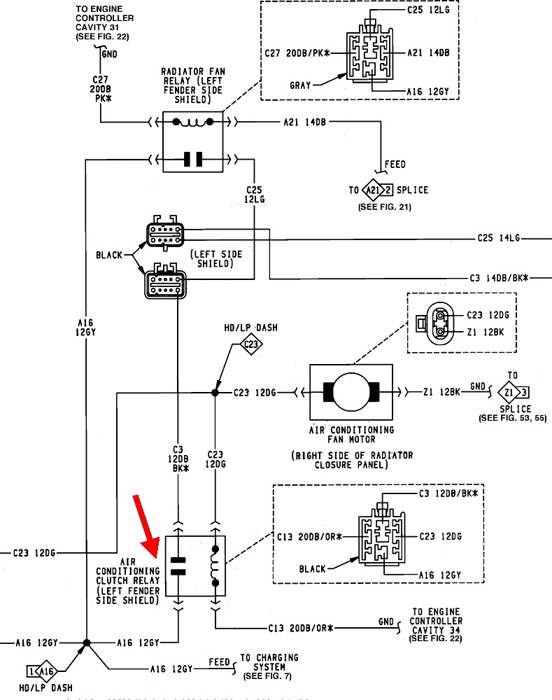
The next step will be to look at the other two wires on that relay and see which part of the circuit is preventing it from turning on.
Was this
answer
helpful?
Yes
No
Tuesday, December 6th, 2022 AT 4:55 PM
Tiny
DAVE FONZA
  • MEMBER
  • 12 POSTS
I am using the fitting that's on top of the compressor. The system has been retrofitted with 134 fittings. My Freon installation kit consists of one end that screws on to the can, a gauge, and an end that snaps on to the fitting on the compressor.
The gauge has two ways to read - PSI and "Add, Full and Overcharged".
40 PSI/Full is what I was reading and when I jumped the clutch to operate, the needle went from 40 to below zero. I just figured that if the gauge is showing below 0 PSI it needs more Freon since I don't see a reading and since I am now able to jump the clutch to work. I don't own a vacuum pump so I can't evacuate the system. I've used the sight glass method before so I will see if there are bubbles or not.
Was this
answer
helpful?
Yes
No
Tuesday, December 6th, 2022 AT 5:39 PM

Please login or register to post a reply.

Sponsored links