Wont start looking for ideas cause I really have none

Tiny
94 TRANSAM
  • MECHANIC
  • 680 POSTS
Ok so Im more lost now than when I began. Im thinking exorcism now. There is absolutely nothing wrong in the motor. I have no idea what the grinding was I guess the hard spot was compression cause the plugs were in. I yanked the plugs and it spins quiet and easy now so I have no idea.
I still cant see how a harness issue would cause this.
So tomorrow Im going to rip the harness open and check every wire for end to end continuity. If I dont find anything then I give up and ill just dump it at the dealer.
Was this
answer
helpful?
Yes
No
Saturday, June 26th, 2021 AT 9:43 PM
Tiny
DANNY L
  • MECHANIC
  • 5,648 POSTS
Burn it with fire! Hahahahahaha Kidding. I love 88-98 OBS Chevy's. I've owned 2.
Was this
answer
helpful?
Yes
No
Wednesday, June 30th, 2021 AT 10:38 PM
Tiny
94 TRANSAM
  • MECHANIC
  • 680 POSTS
Hey guys I dont have access to our 2 resources for info. Can someone look up a 97 tahoe 5.7 4x4 auto and tell me were the 2 grounds on the top center plug on the PCM go to.
Was this
answer
helpful?
Yes
No
Saturday, July 10th, 2021 AT 11:56 AM
Tiny
STEVE W.
  • MECHANIC
  • 12,993 POSTS
What color connector? There are a few for the PCM. C1 (blue) pin 23 and C3 (white) pin 17 are black/white wire and goes to the thermo housing stud.
C3 (white) pin 18 (solid black wire) is a primary ground that runs through the system and also connects to pin 12 in C4 (black) and pin 26 in C2 (red).
Was this
answer
helpful?
Yes
No
Sunday, July 11th, 2021 AT 7:33 AM
Tiny
94 TRANSAM
  • MECHANIC
  • 680 POSTS
Thanks Steve, Yes I have a blue, red, white and black but there is a 5th connector that has 5 pins and 3 are empty. It just has 2 black wires coming off of it. I need to know where they go.
Was this
answer
helpful?
Yes
No
Sunday, July 11th, 2021 AT 9:22 AM
Tiny
STEVE W.
  • MECHANIC
  • 12,993 POSTS
Okay, that is C5 and those wires are just a loop. They are listed as "Service Power" which is something you plug into with the PCM on a bench. Not a ground wire.
Was this
answer
helpful?
Yes
No
Sunday, July 11th, 2021 AT 11:35 AM
Tiny
94 TRANSAM
  • MECHANIC
  • 680 POSTS
Thanks brother
Was this
answer
helpful?
Yes
No
Sunday, July 11th, 2021 AT 4:57 PM
Tiny
94 TRANSAM
  • MECHANIC
  • 680 POSTS
Ok so unless Im stupid this is a nightmare. Need some help tracing this cause I dont have access yet to our sources.

Cam, crank, MAF etc all have pink wires which I assume is the reference voltage feed. All my pink wires in the harness read 38.8 ohms to the black and white harness ground everywhere. Also I have 118 ohms between all the green and white and pink. Traced the green and white back to the relays in the fuse box under the hood. Dont know if I should have a reading between them but I know I shouldnt have one pink to black.

Can anyone tell me if the pink to green is normal?
Was this
answer
helpful?
Yes
No
Thursday, July 15th, 2021 AT 12:10 PM
Tiny
STEVE W.
  • MECHANIC
  • 12,993 POSTS
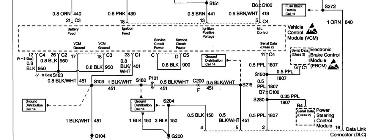
That is going to be impossible to say as the Pink wire should be battery voltage feed to all those items and is fed from multiple fuses. ECM-1 and ENG-1 cover most of the powertrain feeds. However the resistance is going to vary depending on what is on the circuits.
ENG-1 feeds the EGR, purge valve, cam sensor, O2 sensors, MAF as well as a feed to the ECM.
ECM-1 feeds crank sensor, injectors, ignition coil and driver module, and a feed for the ECM.
To test them you would be better off pulling the connections and testing to see if the 12 volt feed changes. For instance if you test it and the battery voltage is at 12.6 volts but testing the pink wire shows 10.6 then you have a problem, pull the connectors off each part in the circuit until the full voltage returns, then test the part that you pulled last.
Was this
answer
helpful?
Yes
No
Thursday, July 15th, 2021 AT 5:14 PM
Tiny
94 TRANSAM
  • MECHANIC
  • 680 POSTS
Nothing is connected. No battery, motor is out and the whole harness is cut open to trace wires. So Im not testing voltage Im testing continuity from each wire at the sensor plug to each pin on the PCM plugs. Thats how I found continuity from the pink on every sensor to 5 other wires at the harness connectors.

So thus my confusion cause as you listed ENG 1 and ECM 1 run different sensors but both those circuits test 38.8 ohms to ground. Which is off the planet odd that 2 circuits test the same to ground. And there is no reason I should have any reading at all to ground when neither end of the harness is plugged into anything. And I can find any melted wires. Blowing my mind.

I literally traced the pink from one end to the other and found nothing wrong so how is it finding a path to the black/white? There has to be a branch that goes through the firewall or something.
Was this
answer
helpful?
Yes
No
Thursday, July 15th, 2021 AT 9:54 PM

Please login or register to post a reply.

Sponsored links