Voltage fluctuation?

Tiny
PETER1974
  • MEMBER
  • 2007 CHRYSLER SEBRING
  • 2.4L
  • 4 CYL
  • 2WD
  • AUTOMATIC
  • 149,129 MILES
In 2008, when the car's engine was running, the air volume of the air conditioner was large, the hourly fog lights flashed abnormally, and the air volume of the air conditioner fluctuated abnormally when the accelerator was stepped on. If the engine is turned off, the air volume of the air conditioner is normal, and the fog lights are normal, what is the problem?
Replaced it with a new alternator, new battery pulley electric blower, resistance blower, TIPM fuse box but the problem is still not resolved.
Tuesday, July 26th, 2022 AT 10:15 AM

15 Replies

Tiny
AL514
  • MECHANIC
  • 4,099 POSTS
Hello, that is definitely a voltage drop issue, or charging system cutting in and out. Did you have the whole vehicle scanned for diagnostic trouble codes? There may be codes stored in other modules besides the engine computer and if you go to autozone or other parts store they can scan the only the engine computer. Do you notice any warning lights on the instrument cluster, any battery lights, anything like that?
I will post the wiring diagrams and a couple things to check. Do you own a basic multimeter that can read voltage up to 20 volts DC?
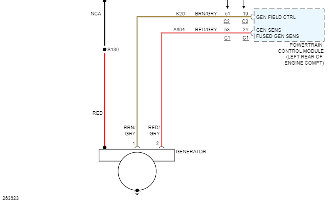
The computer in the vehicle controls the Alternator output by monitoring the charging system voltage on one wire and sending a pulsed signal on other wire to the Alternator, This system is actually a very simple one. But I will post more information shortly.
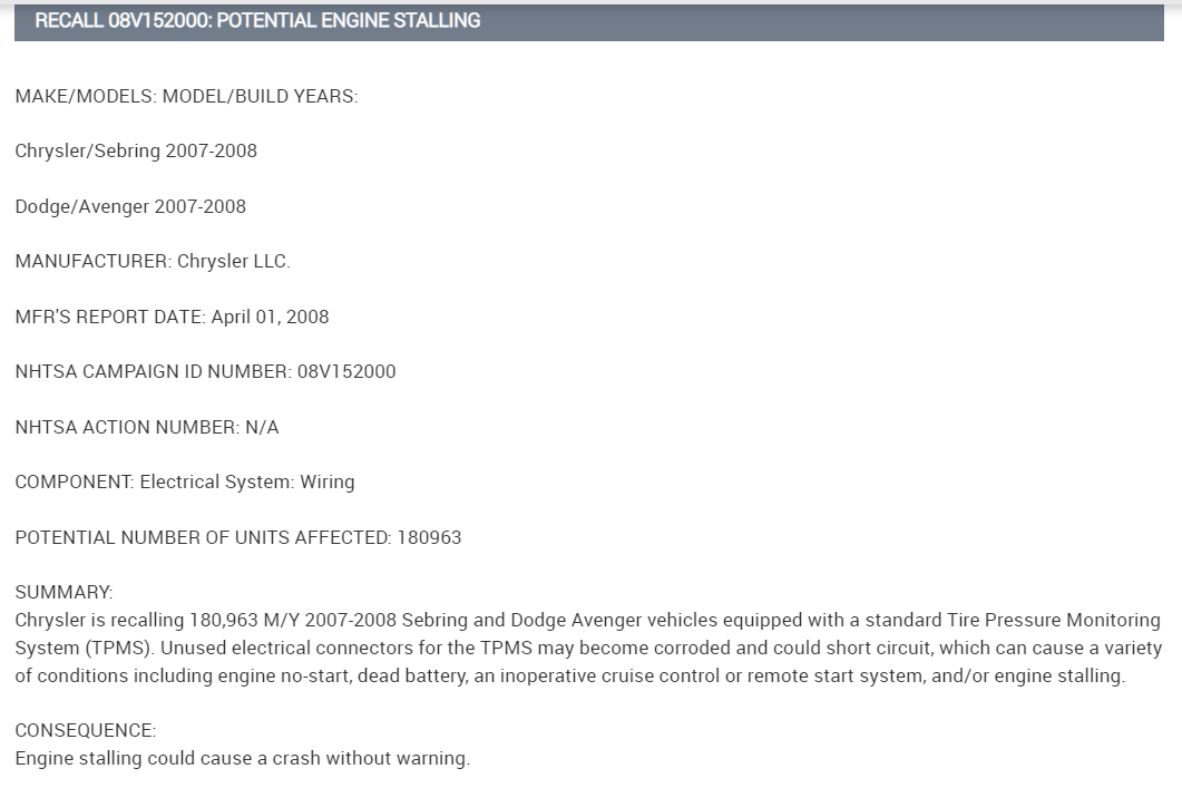
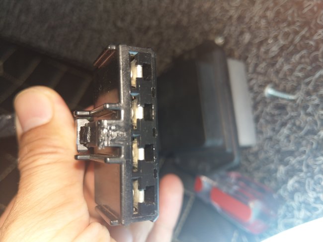
When you replaced the TIPM did you inspect all the connectors, even ones that may be unused. There is a Recall for the unused TIPM connections getting corroded because they are not sealed up from the elements. Since the TIPM is responsible for most of the electrical system. You may want to take a quick look at the TIPM connectors. I will still post more information and if you have a multimeter we can take some voltage readings coming from and going to the TIPM.
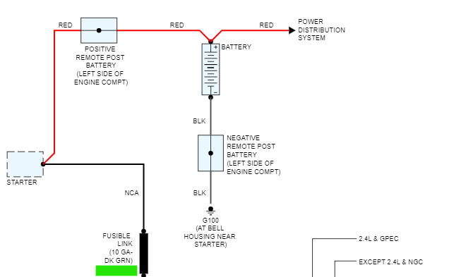
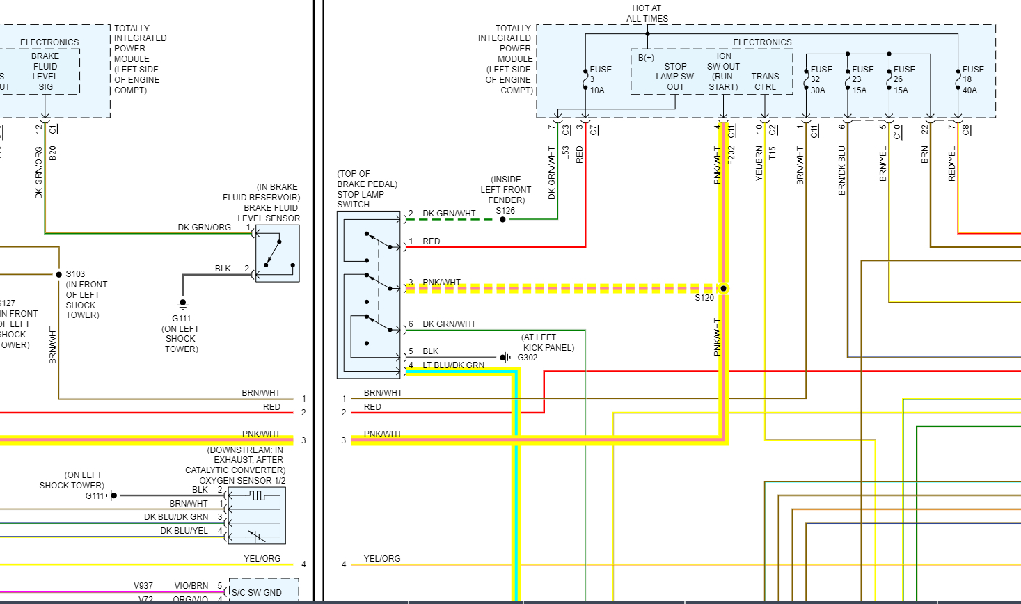
Ok so the first checks after looking at the TIPM connectors is this Fusible Link coming from the Alternator. Diagrams 3 and 4 go together. The Red wire on the left of diagram 4 from the Alternator(Generator) goes to the Fusible Link underlined in Green. It may be near the Starter Motor. Just make sure all connections are tight and clean at the Alternator to begin with. You'll notice the Red wire from the Alternator goes to the Fusible Link, down to the Starter Motor, then to the Positive Remote Post Battery(for jump starting) then to the Battery.
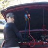
If you have a multimeter, just put the multimeter leads on Battery Positive and Negative with the meter set on 20volts DC. With the engine running and lights, blower motor on what does it read?
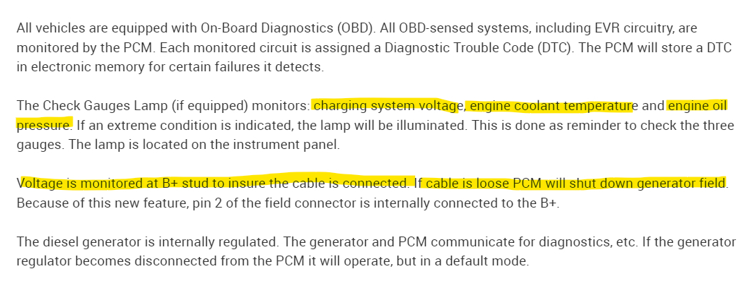
Also you will notice on the last diagram below, Engine coolant temperature and Oil Pressure are Highlighted. If there is any issues with either of these, the charging system will shut down or go into a default state of charging, so if you have those gauges and they look like they are not at their normal readings, that is an issue. I have more checks for you to do, but start with these.

https://www.2carpros.com/articles/how-a-car-electrical-system-works

https://www.2carpros.com/articles/how-to-use-a-voltmeter
Was this
answer
helpful?
Yes
No
+1
Tuesday, July 26th, 2022 AT 10:28 AM
Tiny
PETER1974
  • MEMBER
  • 13 POSTS
Thank you, I will find a professional technician to help me study it.
The problem of unstable voltage has troubled me for 6 months, and there has been no fault code, but these days, the fault code P0703 is sometimes normal.
Was this
answer
helpful?
Yes
No
Tuesday, July 26th, 2022 AT 11:16 AM
Tiny
AL514
  • MECHANIC
  • 4,099 POSTS
You can do a lot of these checks with just a very basic multimeter, I can walk you through a lot of it. But that's up to you. This code is a good lead. This might just be a loose Ground wire or another connector.
Let us know what you find in the end if you take it somewhere to be looked at. Try unplugging the connector on the Brake pedal switch and just start the engine and see if the vehicle responds. You don't have to drive it. If there's a short somewhere on that circuit, the voltage may stabilize.
Was this
answer
helpful?
Yes
No
+1
Tuesday, July 26th, 2022 AT 11:29 AM
Tiny
PETER1974
  • MEMBER
  • 13 POSTS
Thank you very much I will try to find out the problem and get back to you.
Was this
answer
helpful?
Yes
No
Tuesday, July 26th, 2022 AT 11:33 AM
Tiny
PETER1974
  • MEMBER
  • 13 POSTS
Multimeter I still need to learn.
Tried unplugging the connector on the brake pedal switch and starting the engine, but nothing happened.
But I tried fitting these two together, an electric blower with wheels and a resistance blower. To my surprise, the wind speed was steady, and the fog lights didn't flicker. The problem has been solved. After much deliberation, maybe chips of different years are compatible. Thanks to Al 514 for helping me solve my problem.
Was this
answer
helpful?
Yes
No
Wednesday, July 27th, 2022 AT 8:43 AM
Tiny
AL514
  • MECHANIC
  • 4,099 POSTS
Oh, it was the resistor block, that's because on some models it's not a resistor anymore, it's a control module. So, it's not controlled by limiting current but by pulse width modulation. I think that's what happened. Well, I didn't really do anything, you just got the right part in there. Glad it's fixed though. Have a good day.
Was this
answer
helpful?
Yes
No
+1
Wednesday, July 27th, 2022 AT 9:24 AM
Tiny
PETER1974
  • MEMBER
  • 13 POSTS
During this time, the air-conditioning wind speed problem reappeared, but it was not that serious and did not solve the problem at all. How to restart observation and maintenance?
Was this
answer
helpful?
Yes
No
Friday, August 12th, 2022 AT 1:52 AM
Tiny
AL514
  • MECHANIC
  • 4,099 POSTS
What did you actually replace last time, because you did something, either moved a connector, or a circuit is over drawing on current, you replaced a blower control module and its now burned out again. Did the P0703 return? Check the connectors on the blower motor and the control unit and see if they are discolored from getting hot. I have no idea what year components you tried plugging together last time, or what they were. Are the lights dimming as well this time too?
Was this
answer
helpful?
Yes
No
Friday, August 12th, 2022 AT 7:06 AM
Tiny
AL514
  • MECHANIC
  • 4,099 POSTS
The reason your blower motor is being affected so much is because the A/C compressor and the blower motor put a huge load on the electrical system. Thats most likely why it's the first thing you are noticing. The first system to look at would be the charging system. Make sure the voltage level is up where it should be and also make sure that the AC voltage ripple coming out of the Alternator is not exceeding a certain limit. If any of the diodes go bad in the Alternator (there are three sets) you will get AC voltage where you're only supposed to have DC voltage. There is a very low level of AC ripple allowed in automotive electrical systems. If it is too high is can cause all kinds of strange symptoms, I know you replaced it already, but I guarantee the one you bought was a remanufactured one. If there is a problem with the charging system, it can damage the modules and computers in the vehicle.

https://www.2carpros.com/articles/how-to-use-a-voltmeter
Was this
answer
helpful?
Yes
No
Friday, August 12th, 2022 AT 2:34 PM
Tiny
PETER1974
  • MEMBER
  • 13 POSTS
Last time I replaced these two new ones (picture 1 this is the old one)
I checked the connector for discoloration. Color is normal (Picture 2)
After the replacement, the color of the heat sink of the control module is abnormal (Figure 3)
Currently, air conditioners sometimes have normal (not severe) wind speeds when parked and idling. When driving on the highway, the air volume of the air conditioner will decrease when the accelerator is stepped on, and the air volume of the air conditioner will return to normal when the accelerator is released.
Fog lights sometimes flicker (not serious).
Two fault codes P0703, C107C pop up.
Thank you for your hard work.
Was this
answer
helpful?
Yes
No
Thursday, August 18th, 2022 AT 9:30 AM
Tiny
AL514
  • MECHANIC
  • 4,099 POSTS
Okay, I don't think this has anything to do with the HVAC system or air conditioning. They are just a high load, high current draw on the charging system and they are the result of what's happening not the cause. Both codes are for the Brake Pedal Switch, one is stored in the engine computer, and one is stored in the ABS module. The C107C is "Brake Pedal Switch Stuck" and the P0703 is Torque Converter/Brake Pedal Switch B Circuit Malfunction. The Brake Pedal Switch signal tells the Powertrain control module to deactivate the Torque Converter Lock up Solenoid. The Torque Converter locks up to a 1 to1 ratio when the Crankshaft speed and the input shaft speed are the same. When you're on the highway and at a cruising speed, this helps with gas mileage. But I don't think there is any issue with the Torque Converter lock up clutch here,

This might be the whole problem; the first code is pointing towards the Brake Pedal Switch number 2 Circuit which runs from the Totally Integrated Power Module (TIPM) to the Brake Switch and to the ECM. In the diagram the highlighted wires are the problem circuit. They have a splice at S120 and the dotted line wire means there are other circuits involved. If this circuit is in a spot that is intermittently touching/shorting to Ground or shorting to another circuit, this could be causing all these issues. Especially since all these wires run in a harness that is all bundled together. There's no telling which wires it could be shorting to. When the Brake pedal is not pressed you can see on the diagram that the circuit is a complete circuit, it only opens when the brake pedal is pressed.
I have the entire flow chart pulled up for diagnosing the P0703 code. Its step-by-step instructions. But I'm also going to find this Splice S120 and see what else is on that circuit. It doesn't look like there is much protection on that wire, The Fuse 3 is for the Brake Light circuit, not the Number 2 Switch circuit.
The first diagram is the ECM diagram, and the fifth is the ABS diagram, and the fourth is the Code setting criteria for P0703.

The sixth diagram is the location of Splice S120, on the driver side front, very close to the headlights. I would check this location, it's going to be a pink/white wire.
Was this
answer
helpful?
Yes
No
+1
Thursday, August 18th, 2022 AT 1:01 PM
Tiny
PETER1974
  • MEMBER
  • 13 POSTS
Thanks a lot, I'll look into it.
Was this
answer
helpful?
Yes
No
Monday, August 22nd, 2022 AT 12:50 AM
Tiny
AL514
  • MECHANIC
  • 4,099 POSTS
You're going to have to test the circuits on the Brake pedal switch for any voltage or lack of voltage that should or shouldn't be there. It's not difficult with a multimeter, it's only testing on dc volts, it is very easy. I can walk you through all of it.
Was this
answer
helpful?
Yes
No
+1
Monday, August 22nd, 2022 AT 11:53 AM
Tiny
PETER1974
  • MEMBER
  • 13 POSTS
Okay, I got the multimeter ready and I started doing it step by step your way. Thanks
Was this
answer
helpful?
Yes
No
Monday, August 22nd, 2022 AT 9:33 PM
Tiny
AL514
  • MECHANIC
  • 4,099 POSTS
Here's the flow chart for diagnosing the Brake Pedal Switch.
Was this
answer
helpful?
Yes
No
Tuesday, August 23rd, 2022 AT 12:28 PM

Please login or register to post a reply.

Sponsored links