Hi,
Replacing a cylinder head gasket is an in-depth procedure. However, with the right tools, most people should be able to do it. One thing I suggest is to confirm the gasket is the issue. Before starting the job, take a look through this link. It explains how to determine if the head gasket is bad.
https://www.2carpros.com/articles/head-gasket-blown-test
If you determine it is bad, here are the directions specific to this vehicle. The attached pics correlate with the directions.
_______________________________________________
The first thing that will need to be done is removal of the timing chain. Here are the directions for removal and replacement.
______________________________________________
2007 Nissan-Datsun Altima L4-2.5L (QR25DE)
Removal and Replacement
Vehicle Engine, Cooling and Exhaust Engine Timing Components Timing Chain Service and Repair Removal and Replacement
REMOVAL AND REPLACEMENT
TIMING CHAIN
Removal and Installation
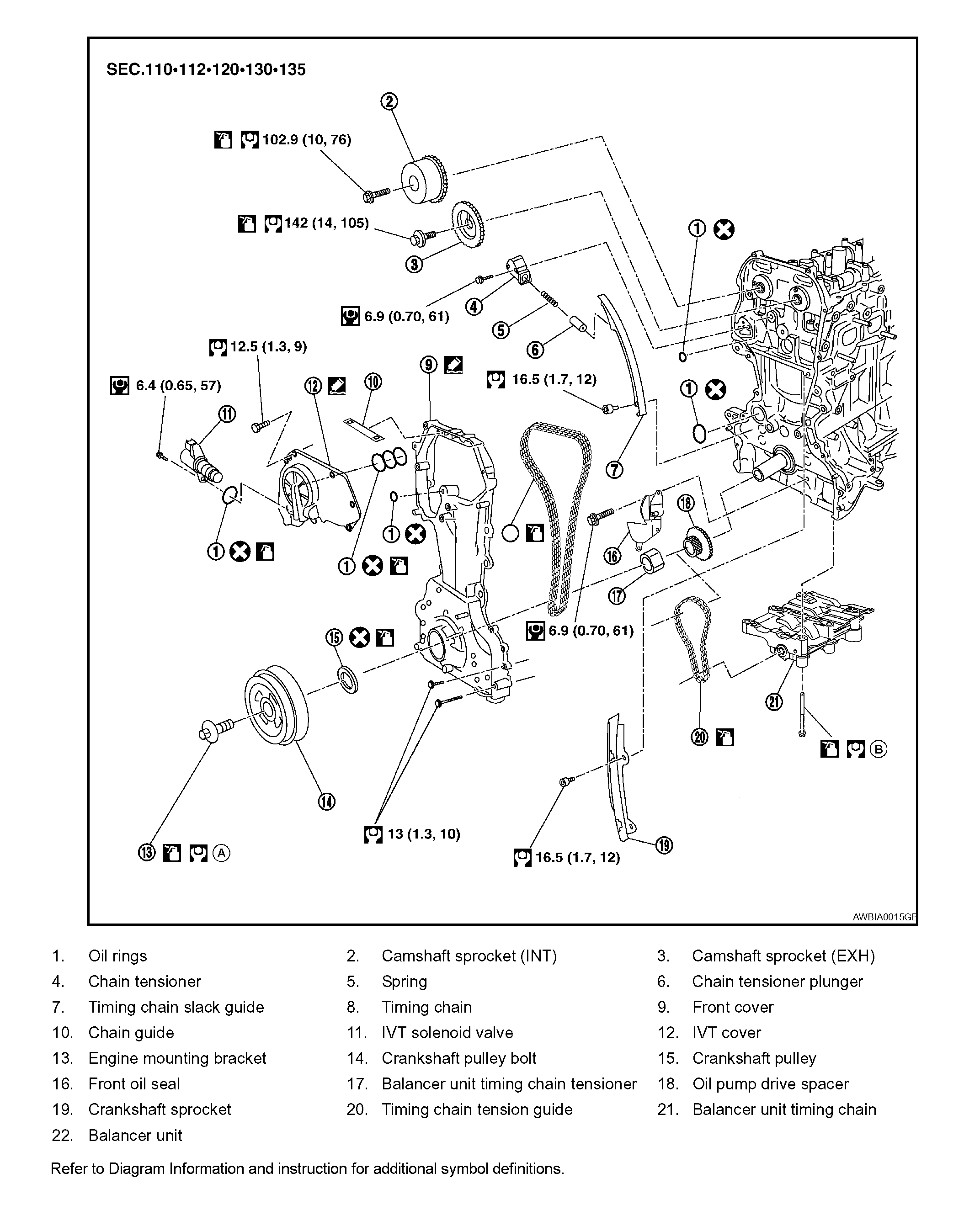
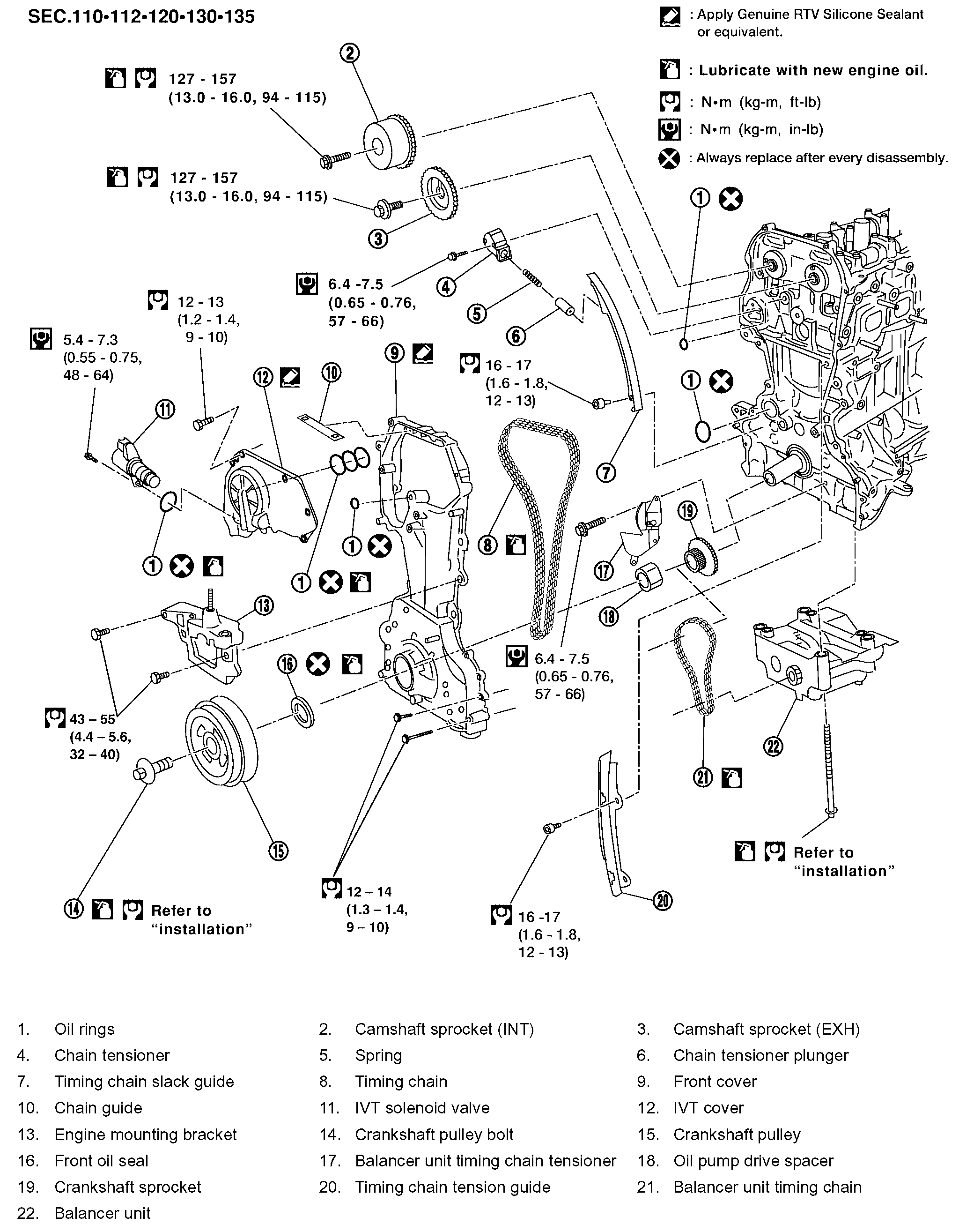
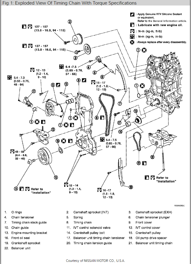
Exploded View EM-51
Pic 1
CAUTION: Apply new engine oil to parts marked in illustration before installation.
REMOVAL
1. Support the engine and transaxle assembly with suitable tools.
2. Remove RH splash shield.
3. Remove the upper and lower oil pan, and oil strainer.
4. Remove generator.
5. Remove engine cover.
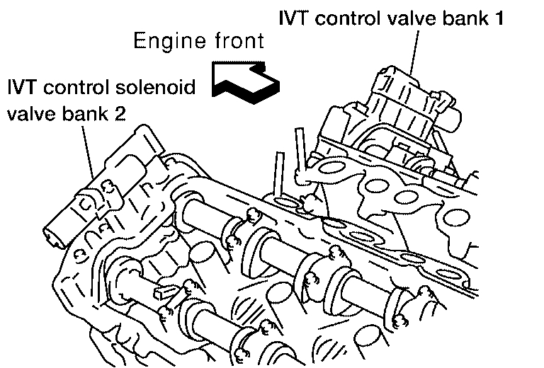
6. Disconnect variable timing control solenoid harness connector.
7. Remove engine ground.
8. Remove the coolant overflow reservoir tank.
9. Position the RH engine compartment fuse and relay box aside.
10. Remove the RH engine mount and bracket.
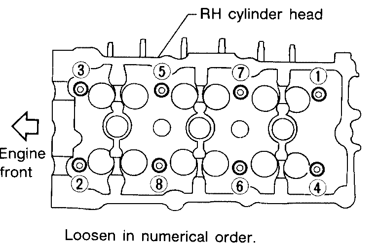
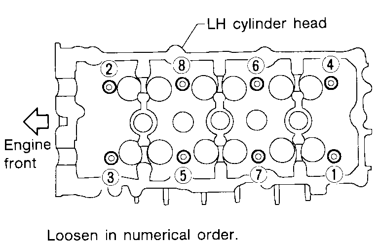
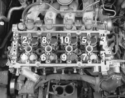
pic 2
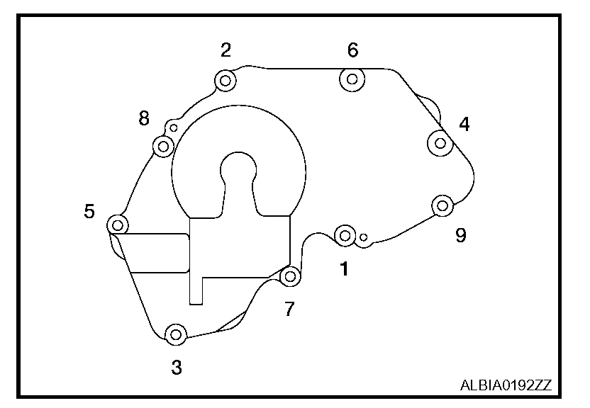
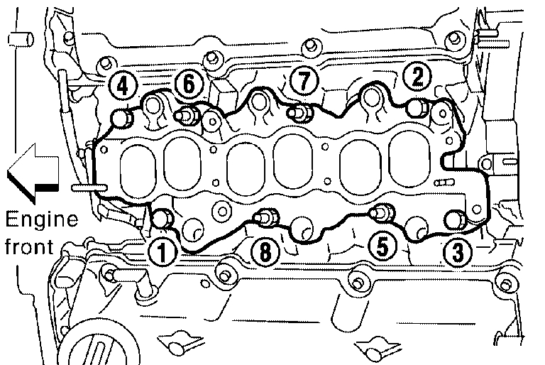
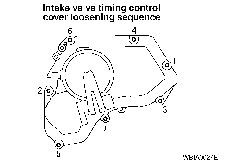
11. Loosen bolts in the numerical order as shown.
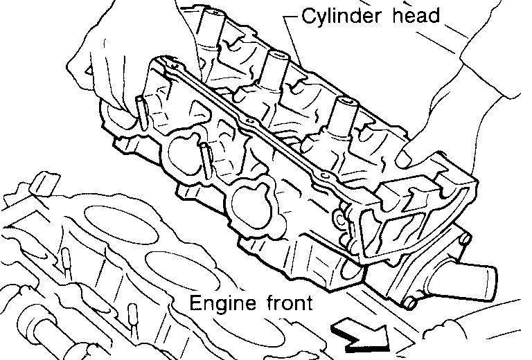
pic 3
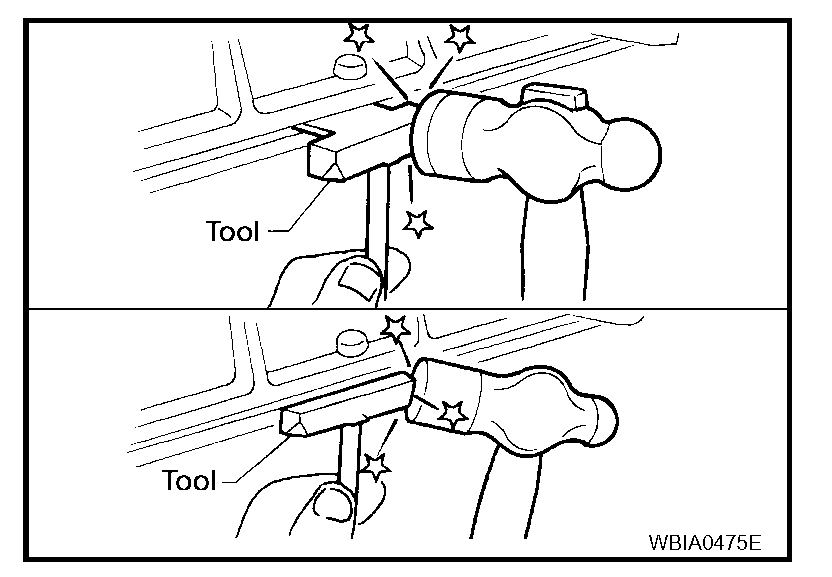
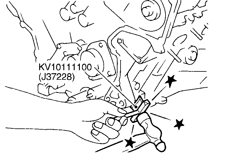
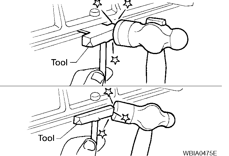
- Remove the IVT (intake valve timing) control cover using Tool.
Tool number: KV10111100 (J-37228)
12. Pull chain guide between camshaft sprockets out through front cover.
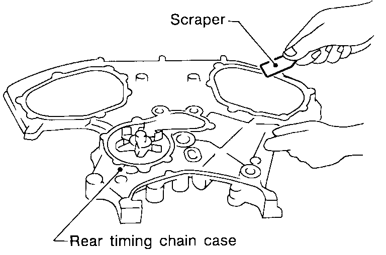
pic 4
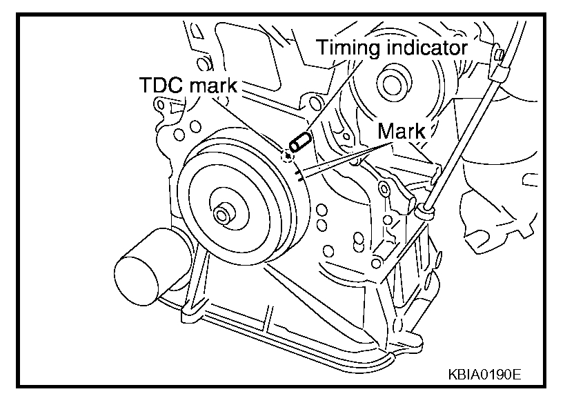
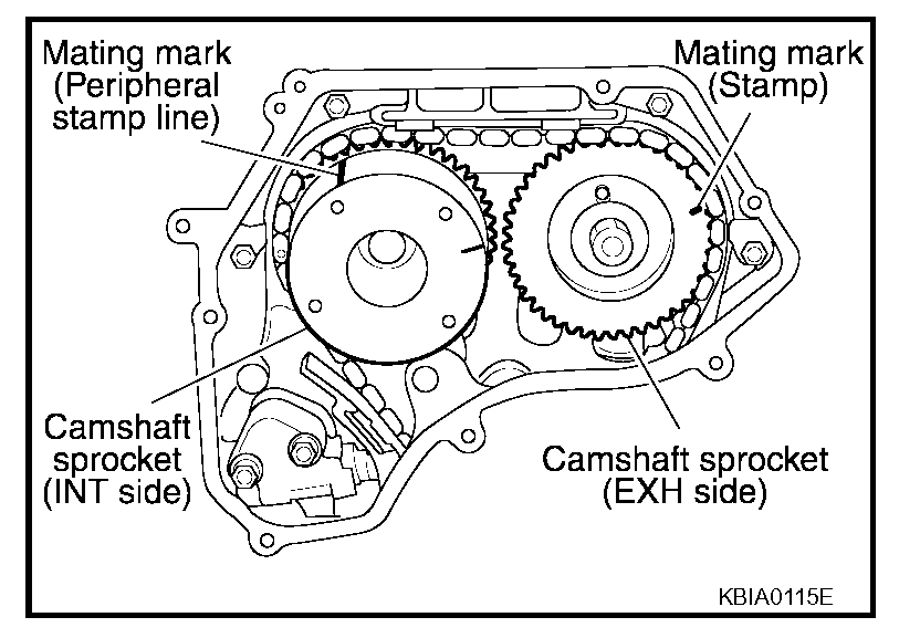
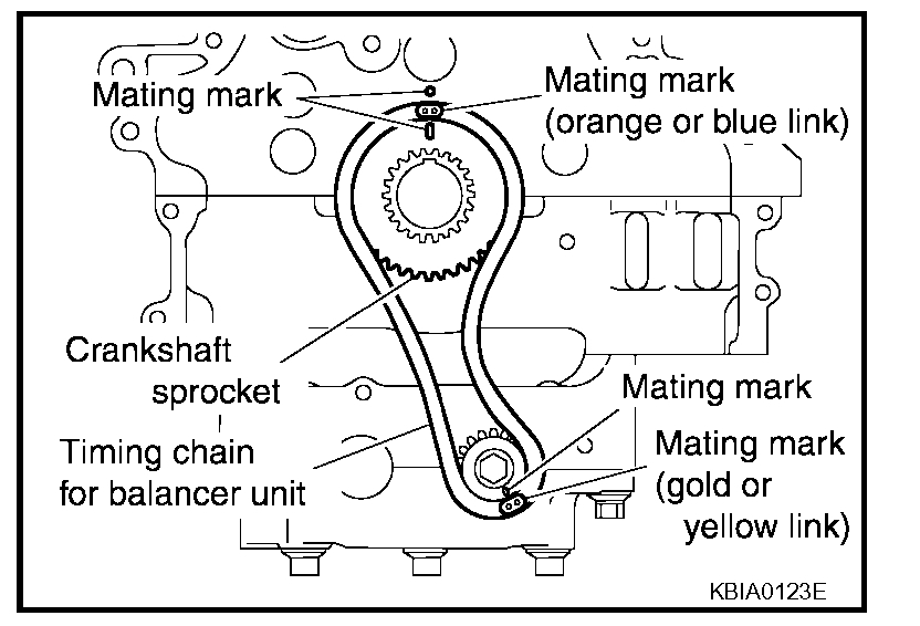
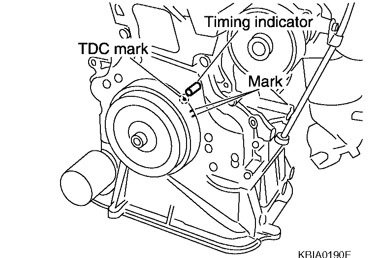
13. Set the No.1 cylinder at TDC on the compression stroke with the following procedure:
a. Rotate the crankshaft pulley clockwise and align the mating marks to the timing indicator on the front cover.
pic 5
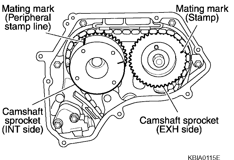
b. Line up the mating marks on camshaft sprockets with the yellow links in the timing chain, and paint an indelible mating mark on the sprocket and timing chain link plate.
- If not lined up, rotate the crankshaft pulley one more turn to line up the mating marks to the positions as shown.
pic 6
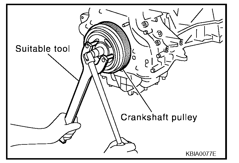
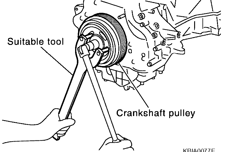
14. Remove crankshaft pulley with the following procedure:
a. Hold the crankshaft pulley using suitable tool, then loosen the crankshaft pulley bolt, and pull the pulley out about 10 mm (0.39 in).
pic 7
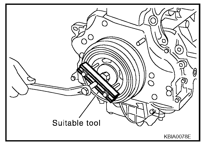
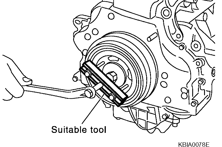
b. Attach suitable pulley puller in the M6 (0.24 in diameter) thread hole on crankshaft pulley, and remove crankshaft pulley using a suitable puller.
pic 8
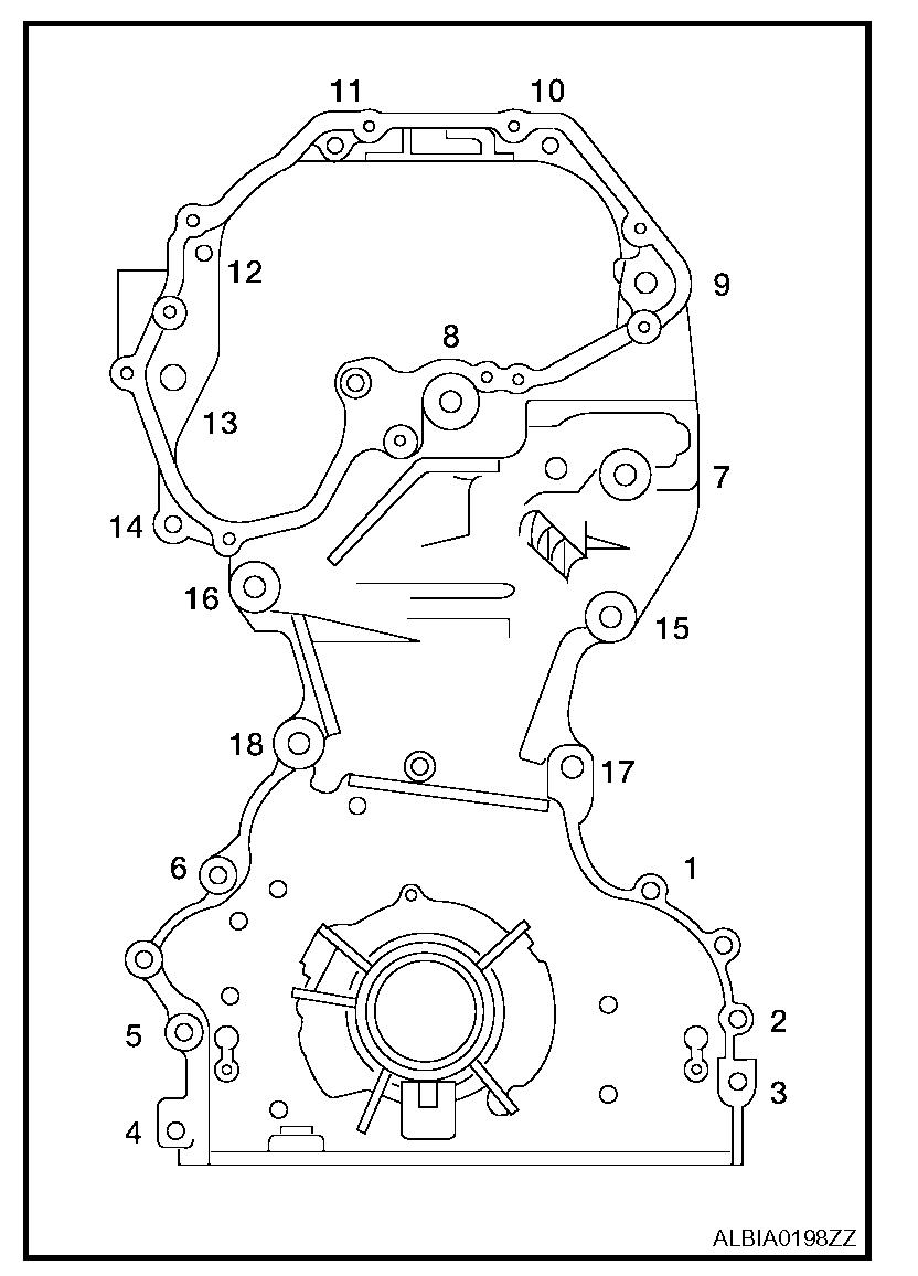
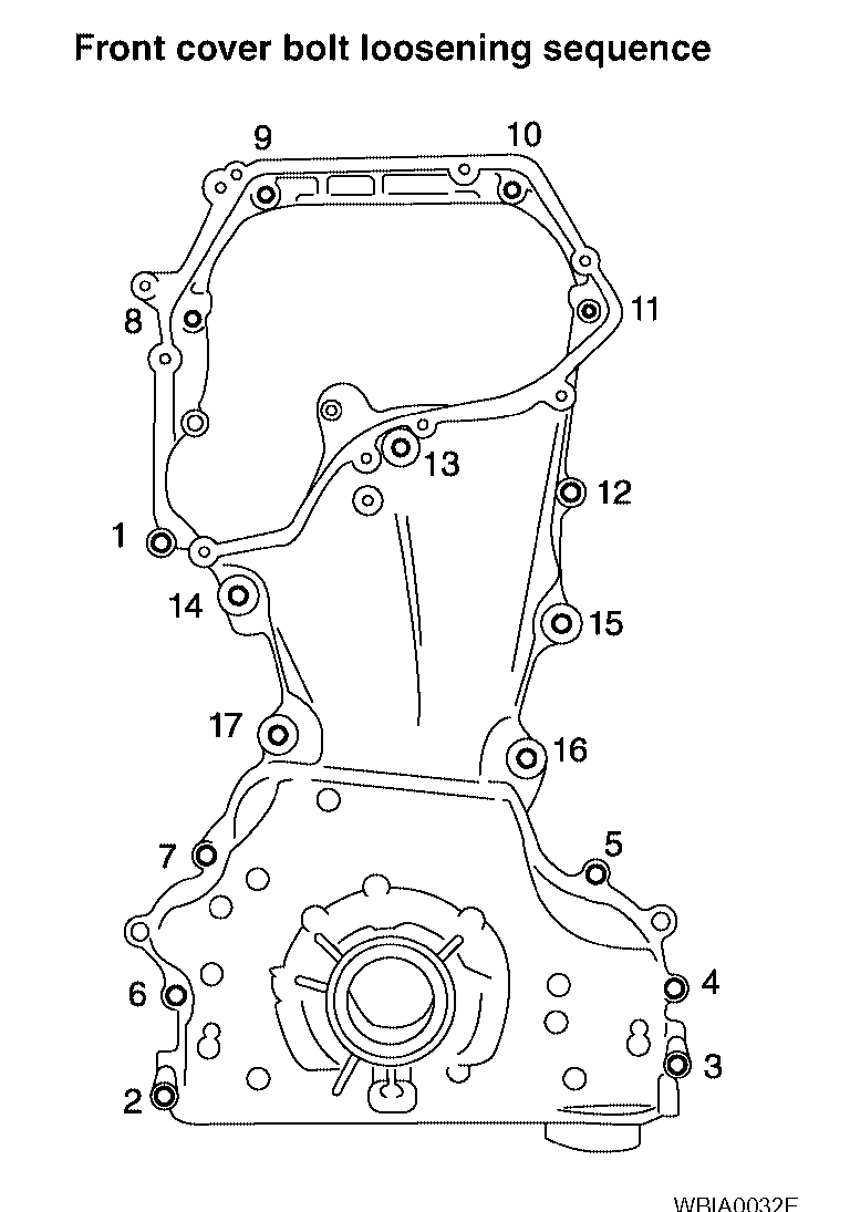
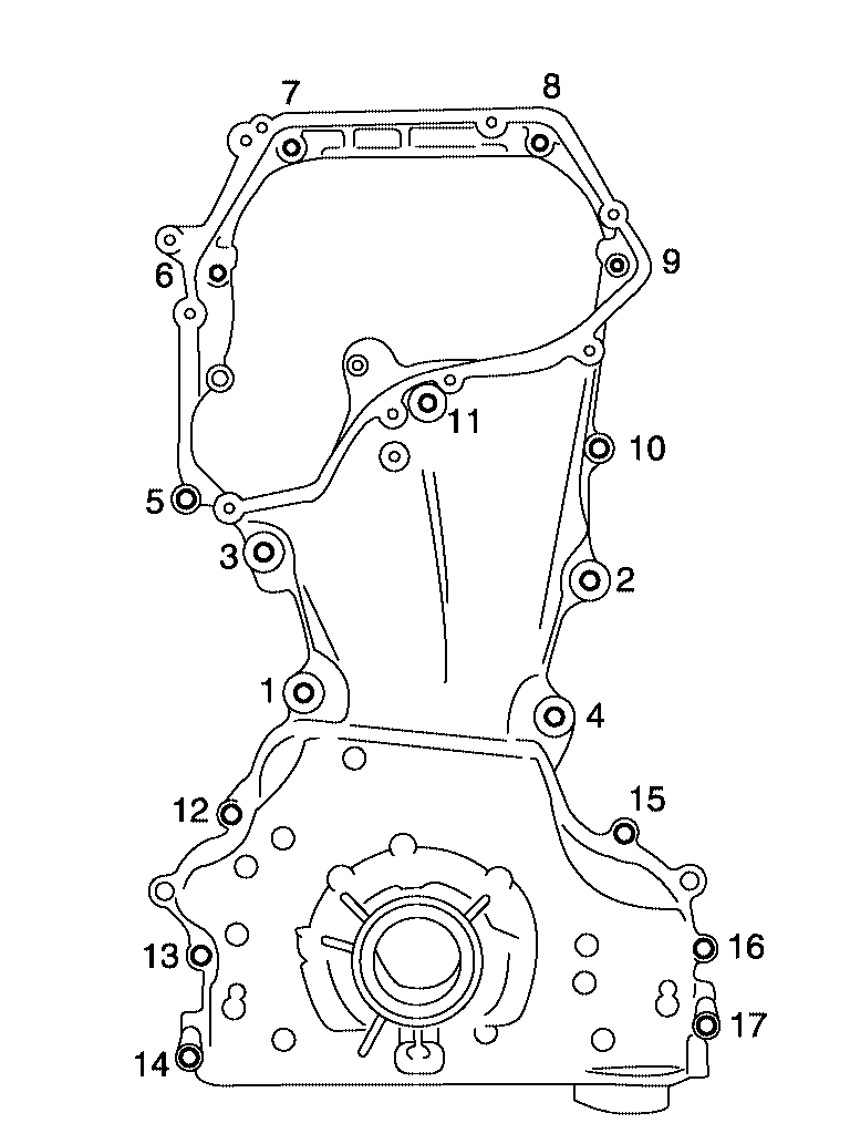
15. Remove the front cover with the following procedure:
a. Loosen the bolts in the reverse order as shown, and remove them.
b. Remove the front cover.
CAUTION:
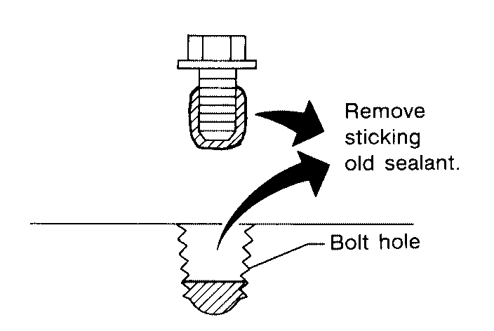
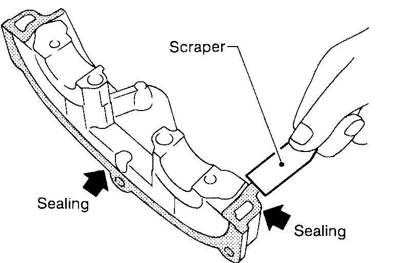
- Be careful not to damage the mounting surface.
16. If the front oil seal needs to be replaced, lift it out with a screwdriver to remove it.
pic 9
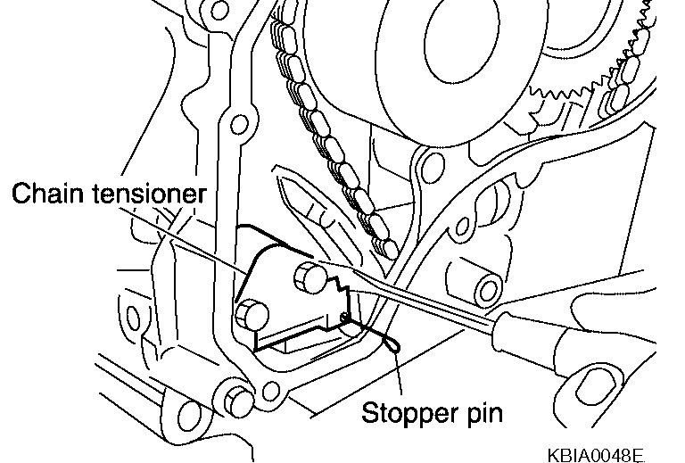
17. Remove timing chain with the following procedure:
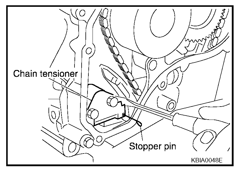
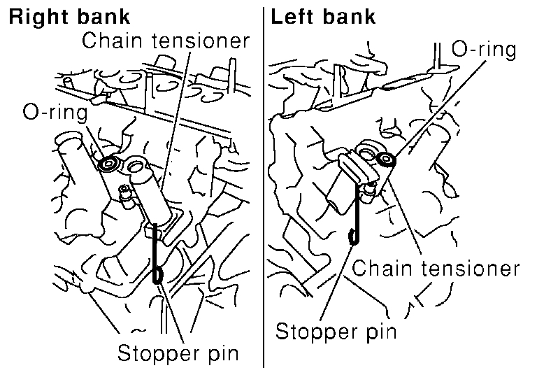
a. Push in the tensioner plunger. Insert a stopper pin into the hole on the tensioner body to secure the chain tensioner plunger and remove chain tensioner.
- Use a wire of 0.5 mm (0.02 in) diameter as a stopper pin.
b. Remove the timing chain.
pic 10
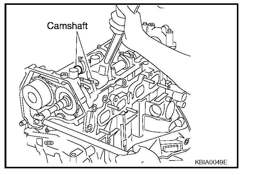
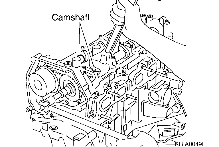
c. Secure hexagonal part of the camshaft with a wrench and loosen the camshaft sprocket bolt and remove the camshaft sprocket for both camshafts.
CAUTION:
- Do not rotate the crankshaft or camshafts while the timing chain is removed. It can cause damage to the valve and piston.
18. Remove the chain slack guide, tension guide, timing chain, and oil pump drive spacer.
pic 11
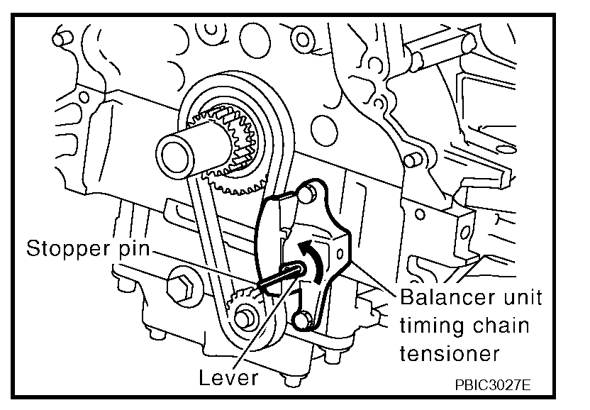
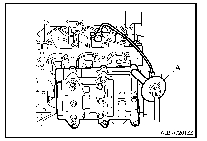
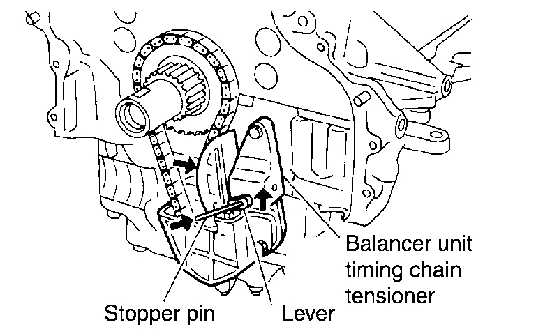
19. Remove balancer unit timing chain tensioner with the following procedure:
a. Lift lever up, and release the ratchet claw for return proof.
b. Push tensioner sleeve in, and hold it.
c. Matching the hole on lever with the one on body, insert a stopper pin to secure tensioner sleeve.
NOTE: Use approximately 1 mm (0.04 in) dia hard metal pin as a stopper pin.
d. Remove the timing chain tensioner for the balancer unit.
20. Secure width across flats of the balancer LH side shaft using a suitable tool. Loosen the balancer sprocket bolt.
21. Remove balancer unit timing chain, balancer unit sprocket and crankshaft sprocket.
pic 12
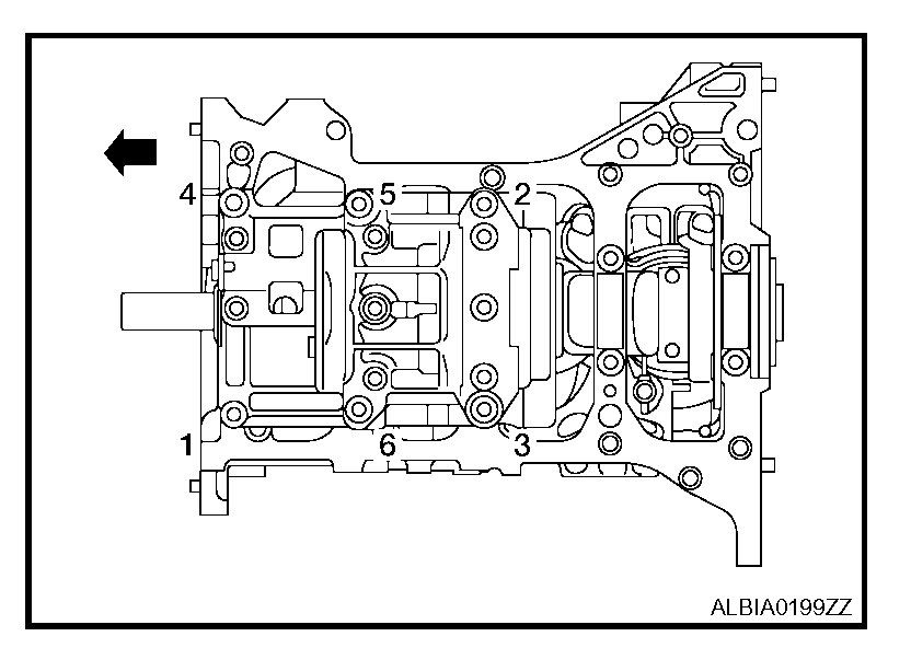
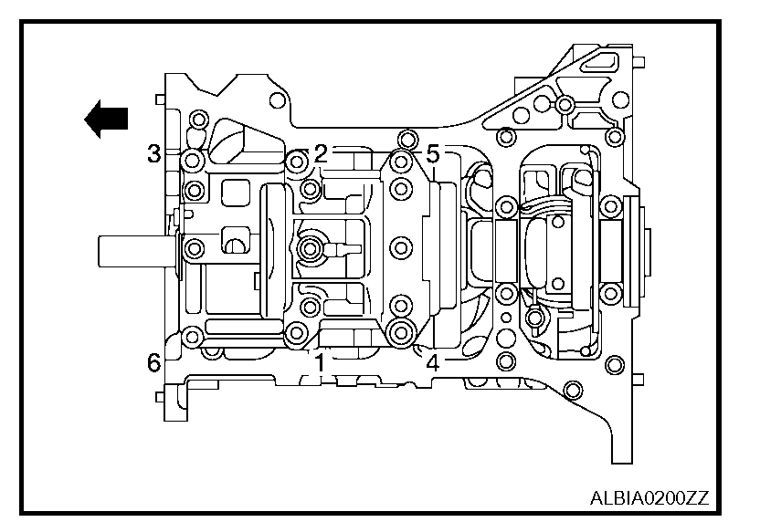
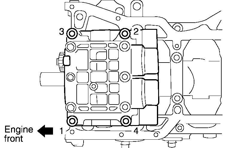
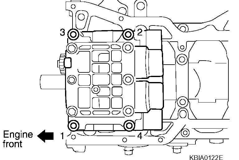
22. Loosen bolts in order as shown, and remove balancer unit.
- Use Torx socket (size E14)
CAUTION:
- Do not disassemble balancer unit.
INSPECTION AFTER REMOVAL
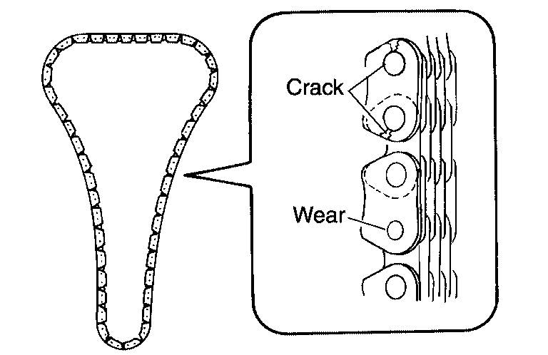
Timing Chain
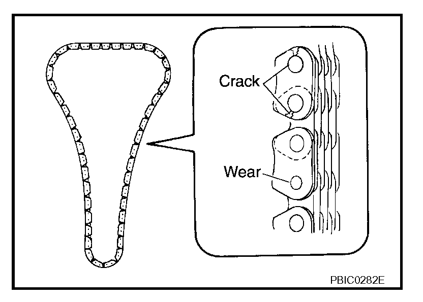
pic 13
Check the timing chain for cracks or serious wear. If a defect is detected, replace it.
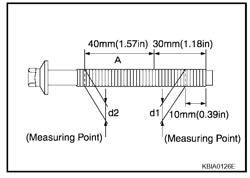
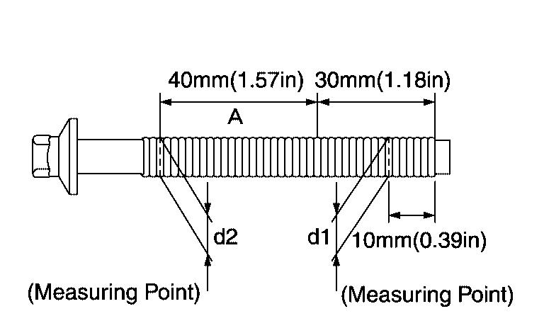
Balancer Unit Bolt Outer Diameter
pic 14
- Measure outer diameters (d1, d2) at the two positions as shown.
- Measure d2 within the range A.
- If the value difference (d1 - d2) exceeds the limit (a dimension difference is large), replace it with a new one.
Limit: 0.15 mm (0. 0059 in) or more
INSTALLATION
NOTE:
- There may be two color variations of the link marks (link colors) on the timing chain.
- There are 26 links between the gold/yellow mating marks on the timing chain; and 64 links between the camshaft sprocket gold/yellow link and the crankshaft sprocket orange/blue link, on the timing chain side without the tensioner.
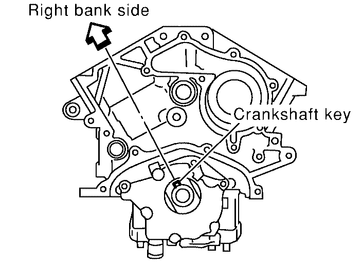
1. Make sure the crankshaft key points straight up.
pic 15
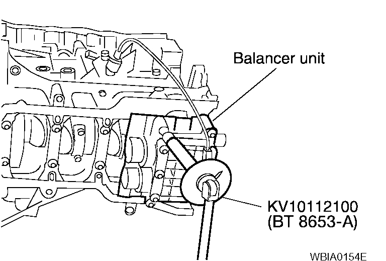
2. Install the balancer unit and tighten the bolts in the numerical order as shown:
CAUTION:
- When reusing a bolt, check its outer diameter before installation. Refer to "Balancer Unit Bolt Outer Diameter".
Tool number: KV10112100 (BT-8653-A)
CAUTION:
- Check tightening angle with an angle wrench or a protractor. Do not make judgment by visual check alone.
- Apply new engine oil to threads and seating surfaces of bolts.
pic 16
Balancer unit bolts
Step 1
Bolts 1-5: 42 Nm (4.3 kg-m, 31 ft-lb)
Bolt 6: 36 Nm (3.7 kg-m, 27 ft-lb)
Step 2
Bolts 1-5: 120°
Bolt 6: 90°
Step 3 (Loosen in reverse order or tightening): 0 Nm (0 kg-m, 0 ft-lb)
Step 4
Bolts 1-5: 42 Nm (4.3 kg-m, 31 ft-lb)
Bolt 6: 36 Nm (3.7 kg-m, 27 ft-lb)
Step 5
Bolts 1-5: 120°
Bolt 6: 90°
pic 17
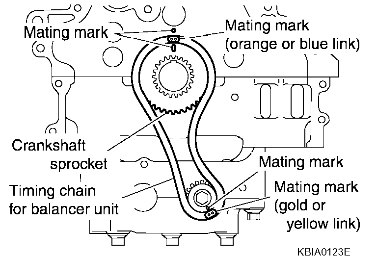
3. Install the crankshaft sprocket and timing chain for the balancer unit.
- Make sure that the crankshaft sprocket is positioned with mating marks on the block and sprocket meeting at the top.
- Install it by lining up mating marks on each sprocket and timing chain.
pic 18
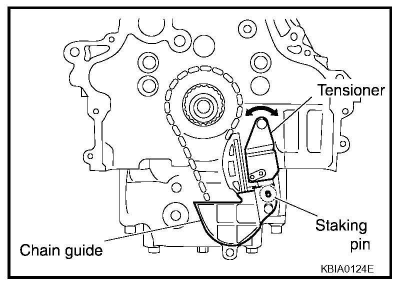
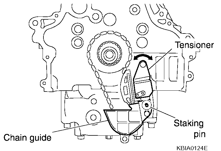
4. Install timing chain tensioner for balancer unit.
NOTE: Chain guide and tensioner move freely with the staking pin as the axle. Therefore, bolt hole position of the three points could be changed during removal. If points change, temporarily tighten the two bolts on the chain guide and move the tensioner to match the bolt holes.
- Be careful not to let mating marks of each sprocket and timing chain slip.
- After installation, make sure the mating marks have not slipped, then remove stopper pin and release tensioner.
pic 19
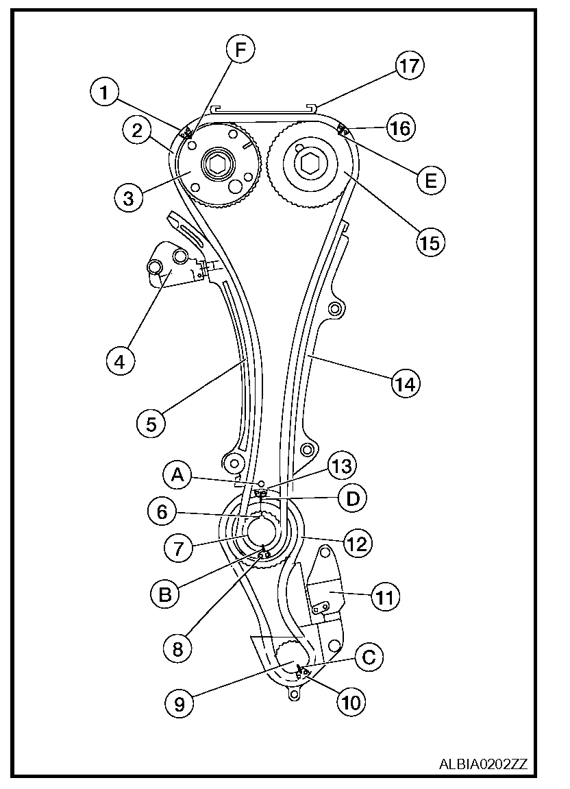
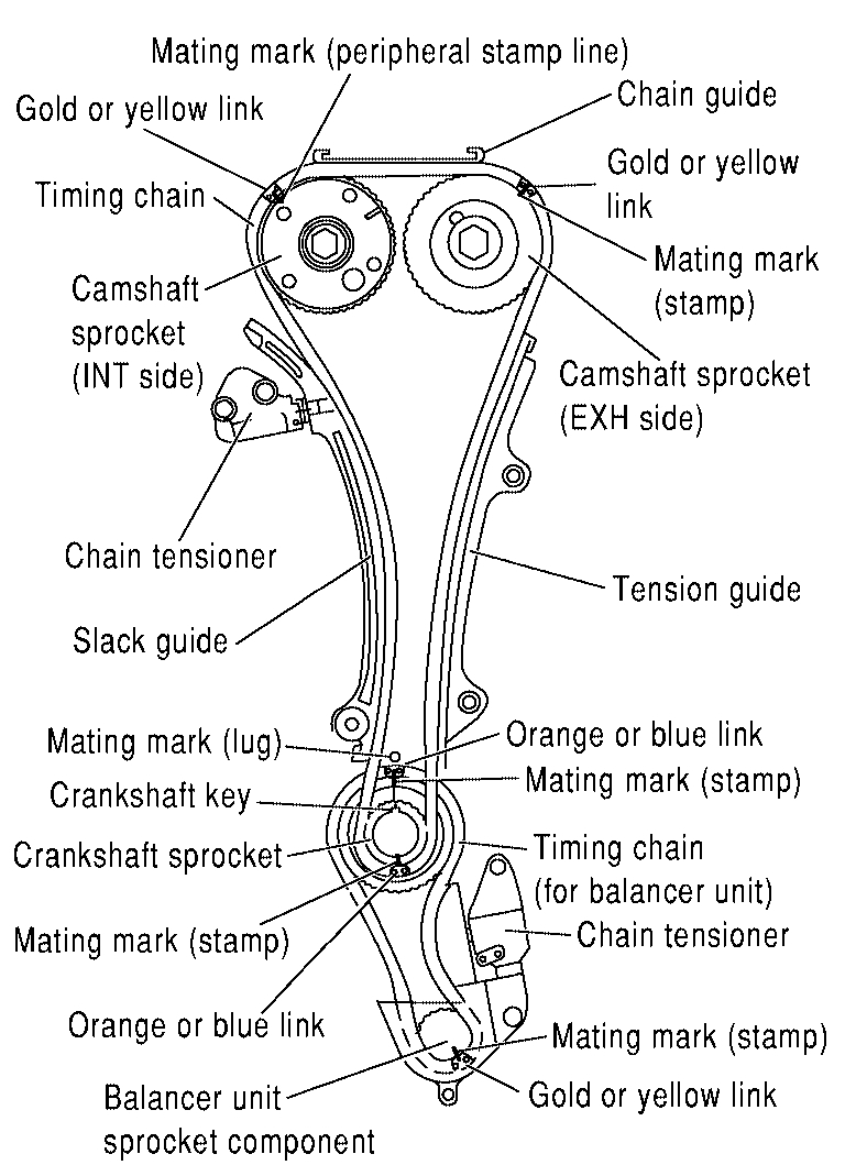
5. Install timing chain and related parts.
- Install by lining up mating marks on each sprocket and timing chain as shown.
- 1 Yellow link
- 2 Timing chain
- 3 Camshaft sprocket (INT side)
- 4 Chain tensioner
- 5 Slack guide
- 6 Crankshaft key
- 7 Crankshaft sprocket
- 8 Orange link
- 9 Balancer unit sprocket component
- 10 Yellow link
- 11 Chain tensioner
- 12 Timing chain (for balancer unit)
- 13 Orange link
- 14 Tension guide
- 15 Camshaft sprocket (EXH side)
- 16 Yellow link
- 17 Chain guide
- A Mating mark (lug)
- B Mating mark (stamp)
- C Mating mark (stamp)
- D Mating mark (stamp)
- E Mating mark (stamp)
- F Yellow link
CAUTION: For the above reason, after the mating marks are aligned, keep them aligned by holding them with a hand.
NOTE:
- Before installing chain tensioner, it is possible to change the position of mating mark on timing chain for that of each sprocket for alignment.
- Before and after installing chain tensioner, check again to make sure that mating marks have not slipped.
- After installing chain tensioner, remove stopper pin, and make sure the tensioner moves freely.
- To avoid skipped teeth, do not move crankshaft and camshaft until front cover is installed.
pic 20
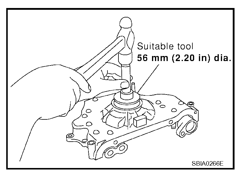
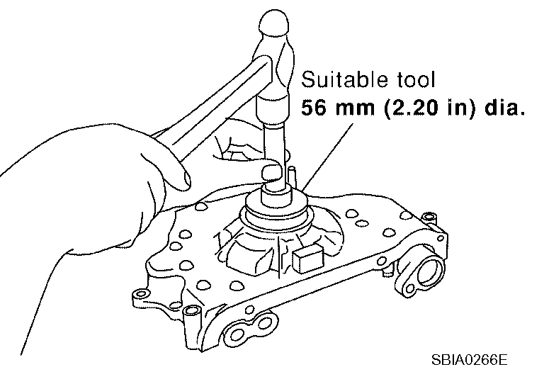
6. Install new front oil seal to front cover, using suitable tool
- Install new oil seal in until it is flush with front end surface of front cover.
CAUTION:
- Be careful not to cause damage to circumference of oil seal.
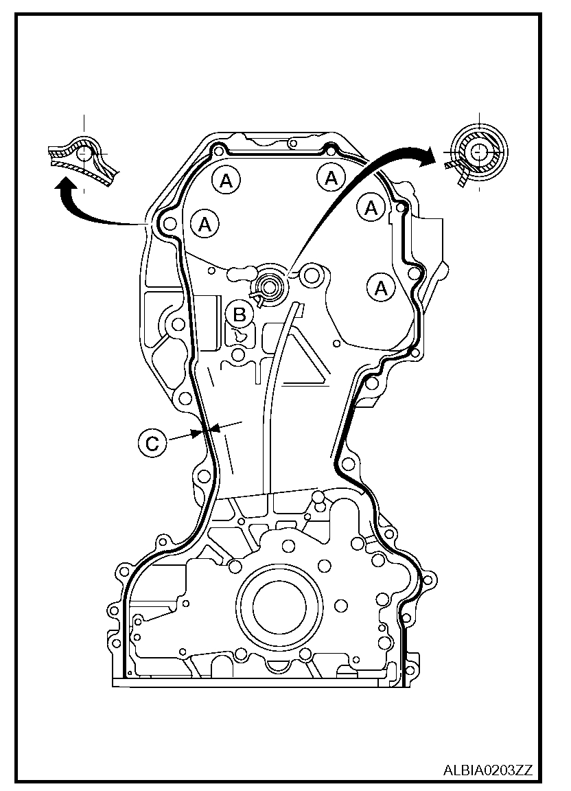
pic 21
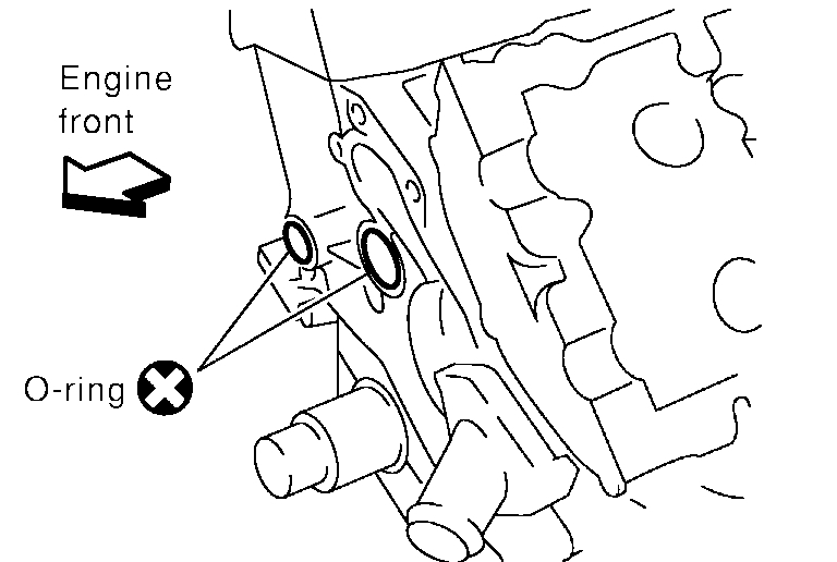
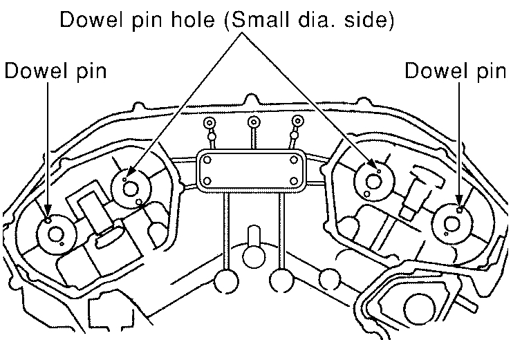
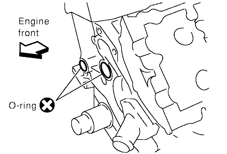
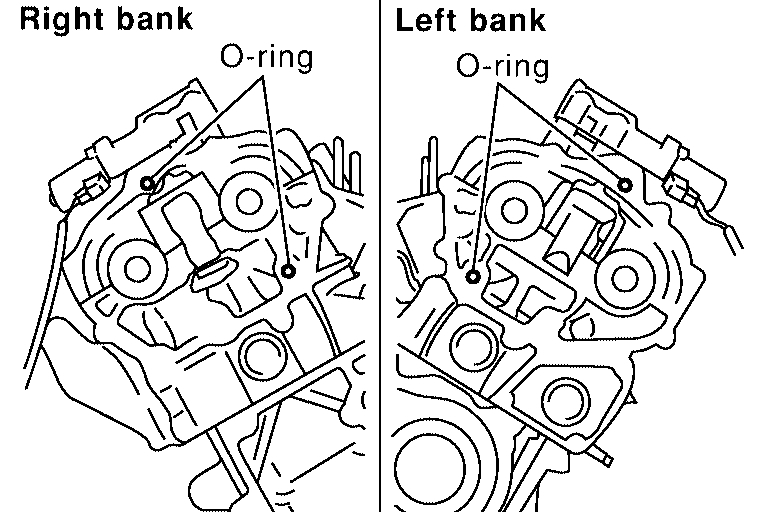
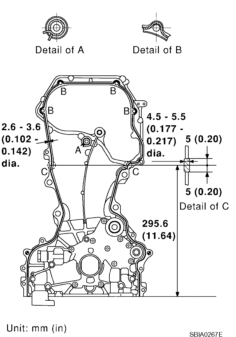
7. Install front cover with the following procedure:
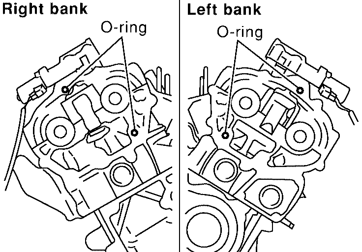
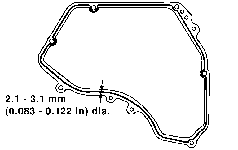
a. Install O-rings to cylinder head and cylinder block.
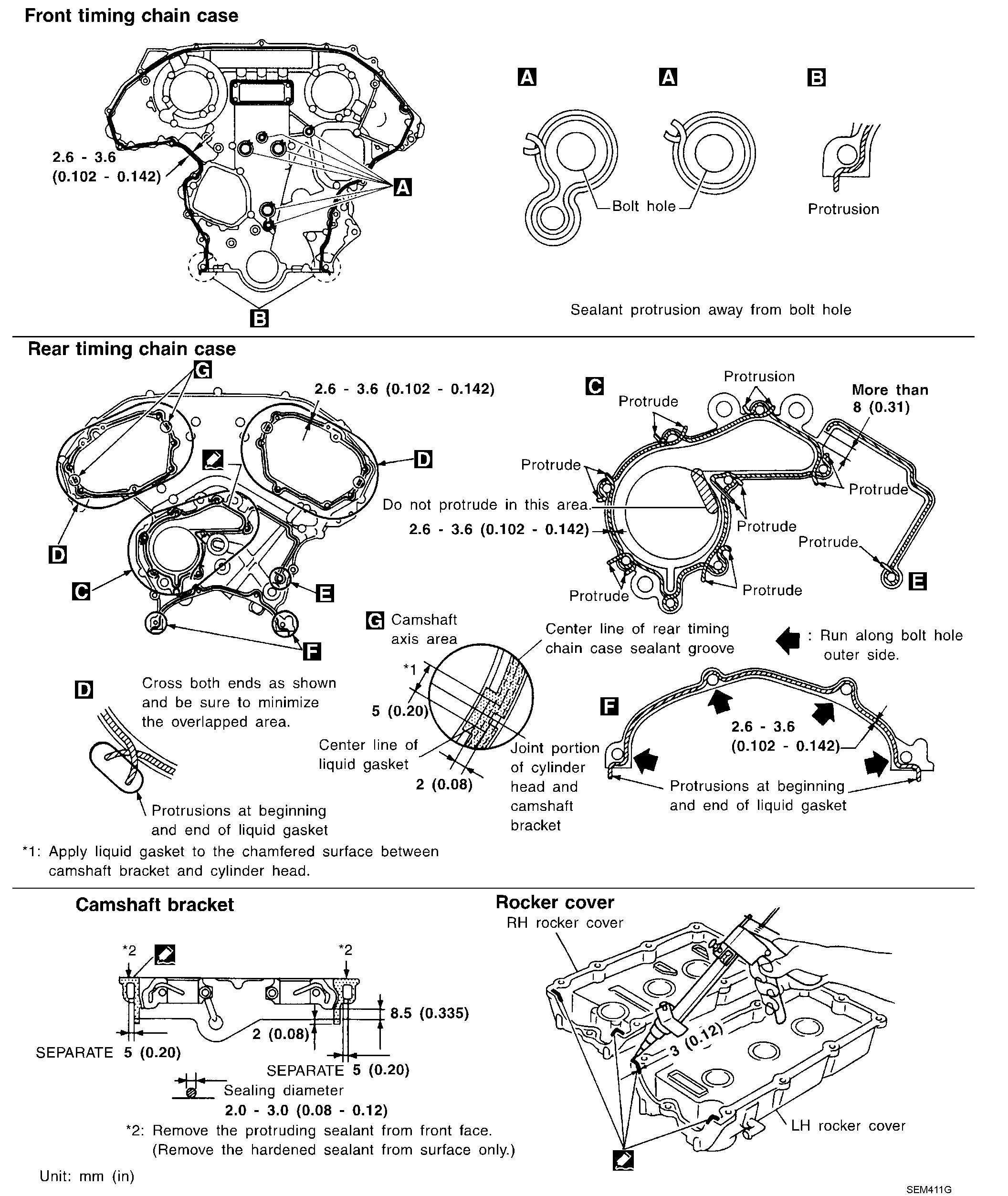
b. Apply Genuine Silicone RTV Sealant or equivalent, to positions specified as shown.
c. Make sure the mating marks on the timing chain and each sprocket are still aligned. Then install the front cover.
Sealant dimension: 3.9 mm (0.154 in) dia.
CAUTION:
- Be careful not to damage the front oil seal during installation with the front end of the crankshaft.
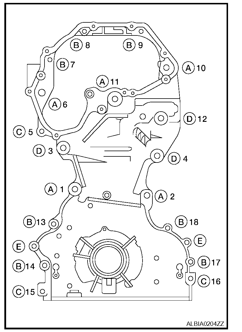
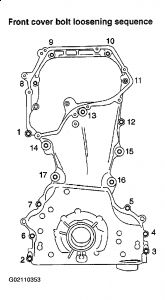
pic 22
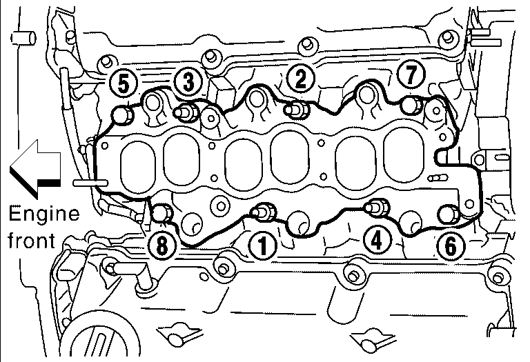
d. Tighten front cover bolts in the numerical order as shown.
e. After all bolts are tightened, retighten them to the specified torque.
Front cover bolts
Bolts A: 49 Nm (5.0 kg-m, 36 ft-lb)
Bolts B: 12.7 Nm (1.3 kg-m, 9 ft-lb)
Bolts C: 12.7 Nm (1.3 kg-m, 9 ft-lb)
Bolts D: 49 Nm (5.0 kg-m, 36 ft-lb)
E Dowel pins
CAUTION: Wipe off any excess sealant leaking at the surface for installing the oil pan.
8. Install the chain guide between the camshaft sprockets.
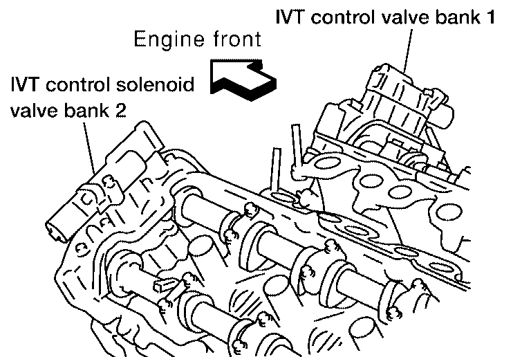
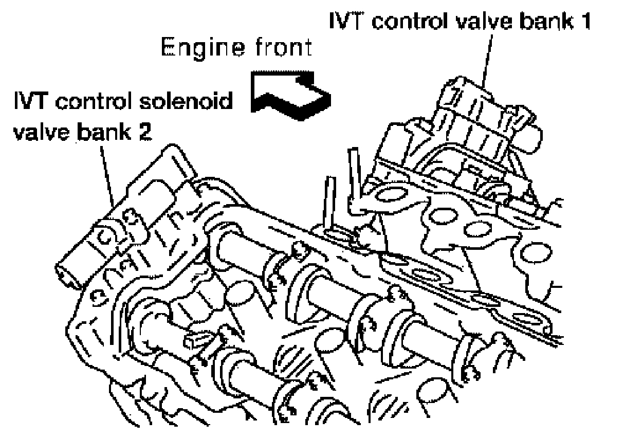
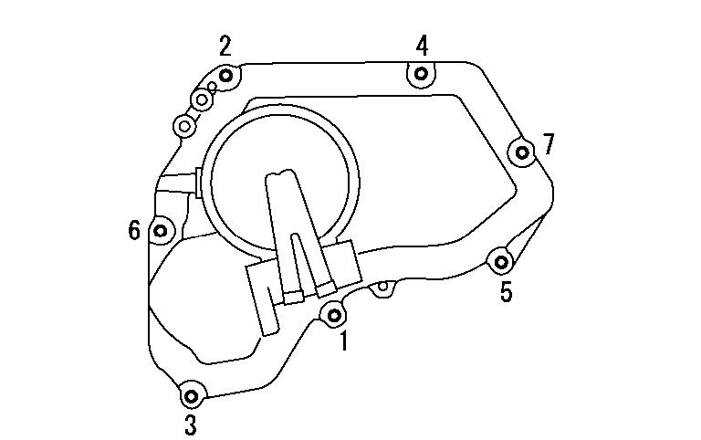
9. Install IVT cover with the following procedure:
a. Install IVT solenoid valve to IVT cover.
b. Install new O-ring to front cover.
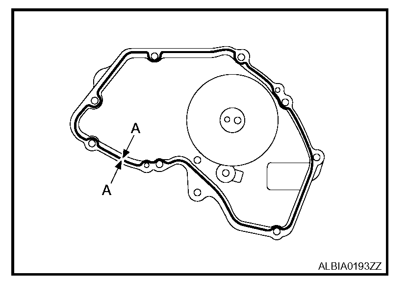
pic 23
c. Apply Silicone RTV Sealant to the IVT cover as shown.
- Apply Genuine Silicone RTV Sealant or equivalent, to positions specified as shown.
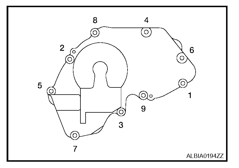
pic 24
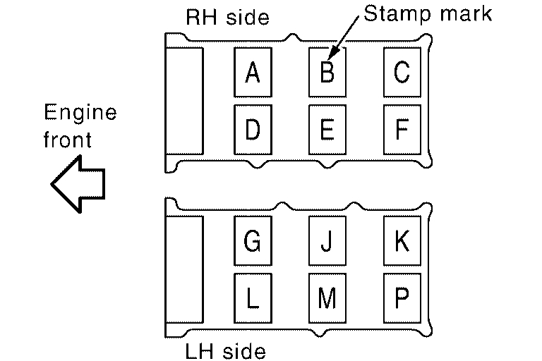
d. Tighten the IVT cover bolts in the numerical order as shown.
10. Insert crankshaft pulley by aligning with crankshaft key.
- Tap its center with a plastic hammer to insert.
- Do not tap the belt hook.
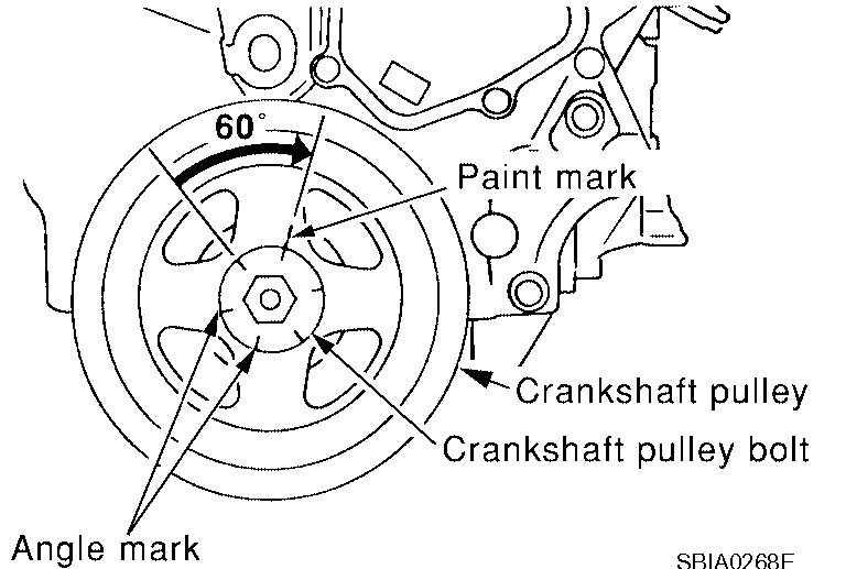
11. Tighten crankshaft pulley bolts.
- Secure crankshaft pulley with a pulley holder to tighten the bolt.
- Perform angle tightening with the following procedure:
a. Apply new engine oil to threads and seat surfaces of bolts.
b. Tighten to initial specifications:
Crankshaft bolt: 42.1 Nm (4.3 kg-m, 31 ft-lb)
pic 25
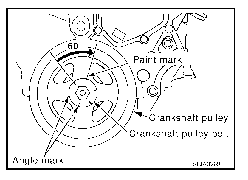
c. Apply a paint mark on the front cover, mating with any one of six easy to recognize stamp marks on bolt flange.
d. Turn crankshaft pulley bolt another 60° to 66° [Target: 60°].
- Check vertical mounting angle with movement of one stamp mark.
12. Installation of the remaining components is in reverse order of removal.
_____________________________________
Cylinder Head Removal and Replacement
Removal and Replacement
Vehicle Engine, Cooling and Exhaust Engine Cylinder Head Assembly Service and Repair Removal and Replacement
REMOVAL AND REPLACEMENT
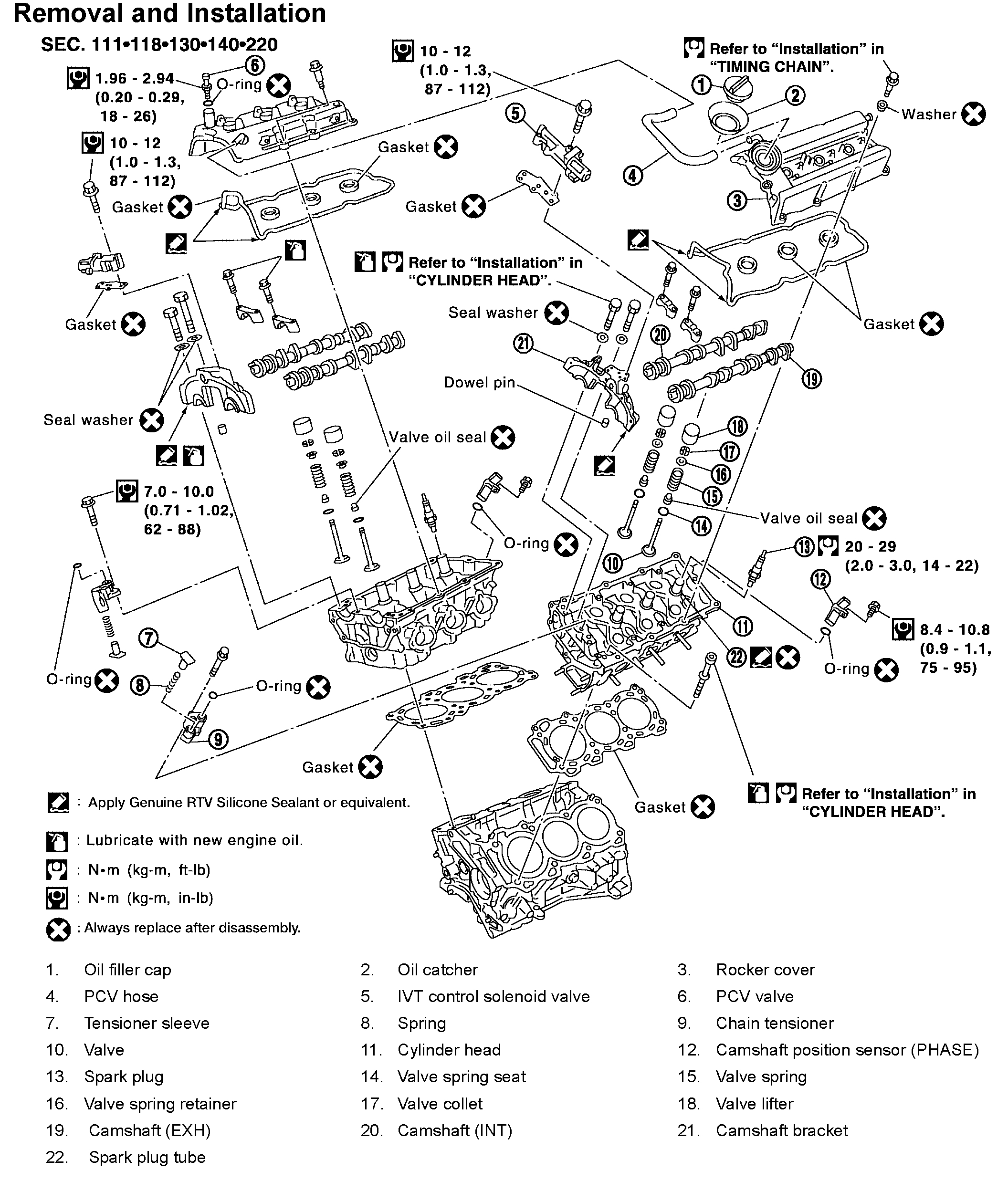
Removal and Installation
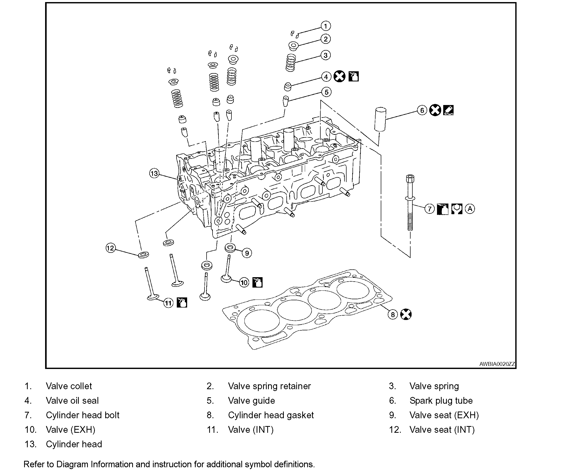
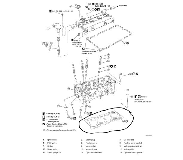
Exploded View EM-63
Pic 26
REMOVAL
1. Remove the timing chain.
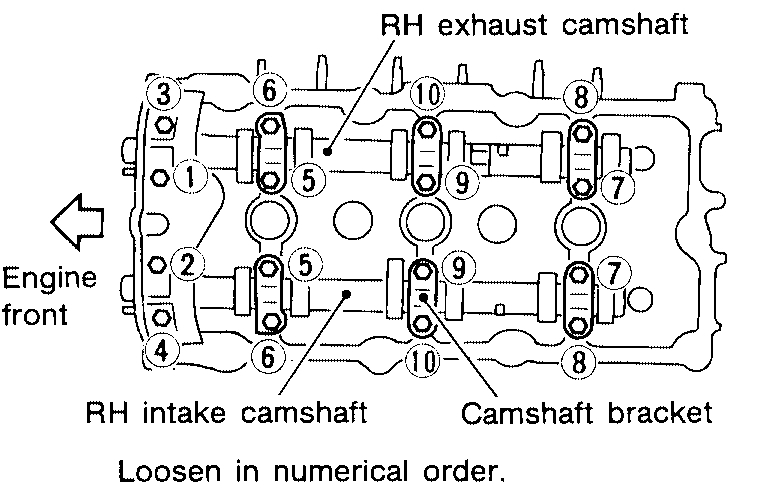
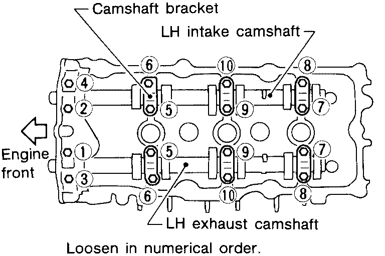
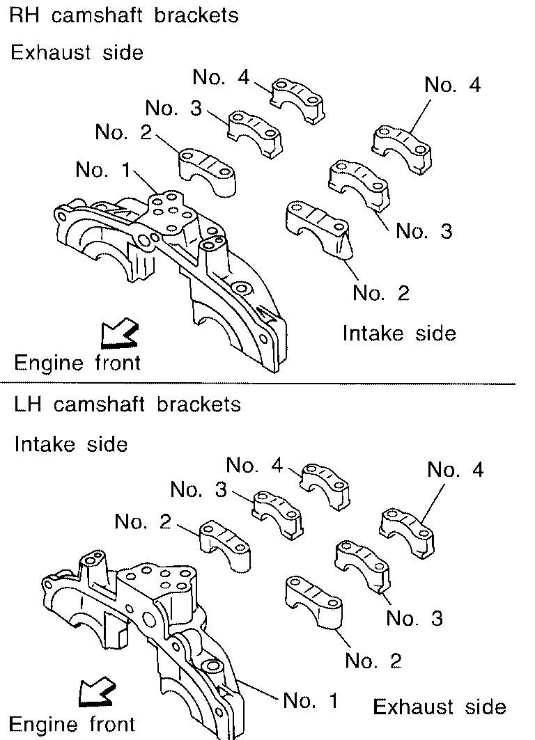
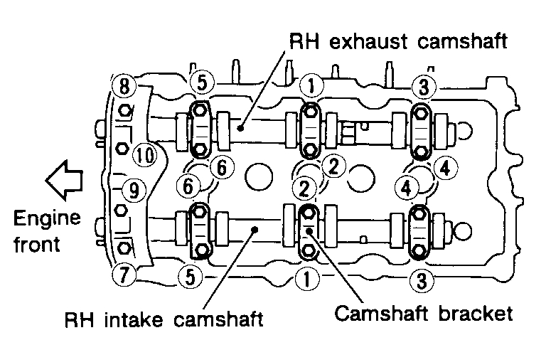
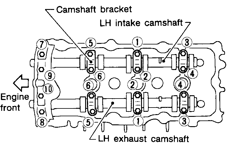
2. Remove the camshafts.
3. Remove spark plugs.
4. Remove the front suspension member.
5. Position the power steering pump and reservoir aside.
6. Disconnect the A/C compressor and position it out of the way with wire.
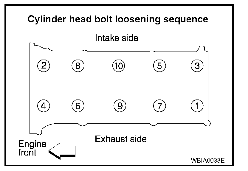
pic 27
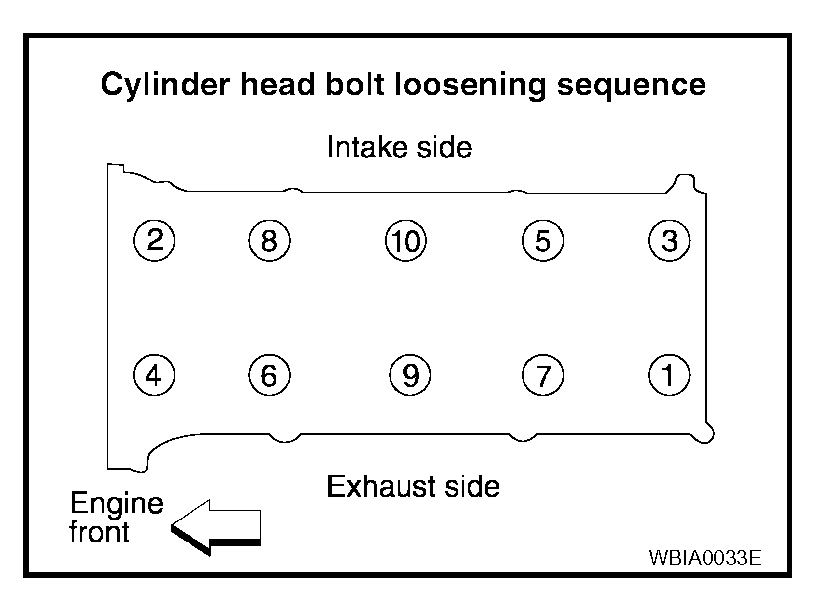
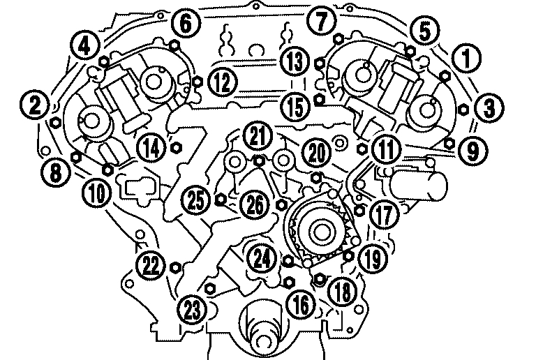
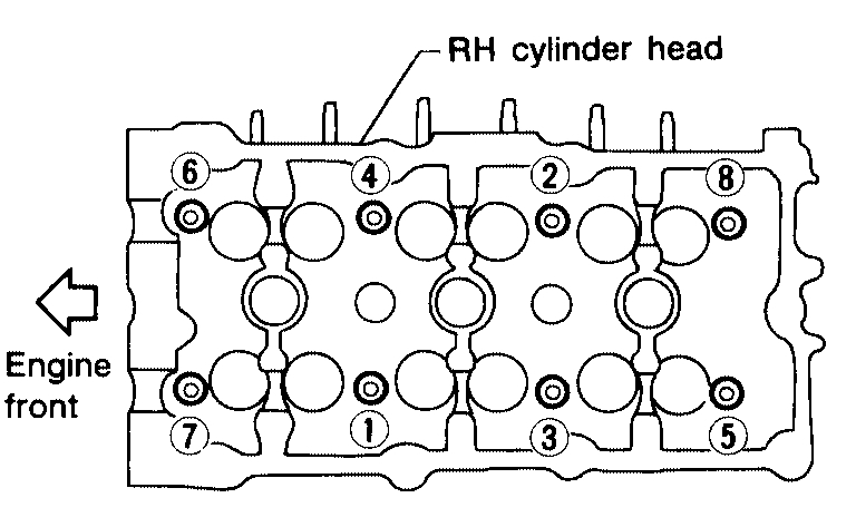
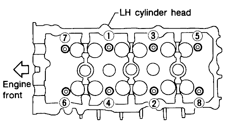
7. Remove cylinder head loosening bolts in the order as shown, using power tool.
8. If necessary to transfer to new cylinder head or remove for reconditioning, remove the intake manifold collector, intake manifold, and fuel tube assembly.
INSPECTION AFTER REMOVAL
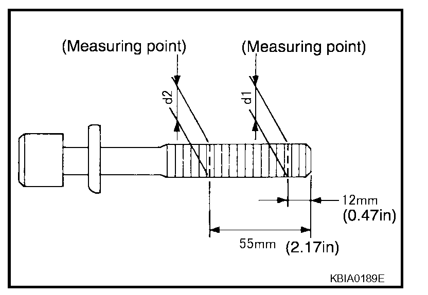
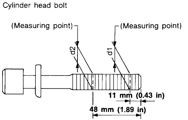
Outer Diameter of Cylinder Head Bolts
^ Cylinder head bolts are tightened by plastic zone tightening method. Whenever the size difference between d1 and d2 exceeds the limit, replace the bolts with new ones.
pic 28
Limit (d1 - d2): 0.23 mm (0.0091 in) or less
^ If reduction of outer diameter appears in a position other than d2, use it as d2 point.
INSTALLATION
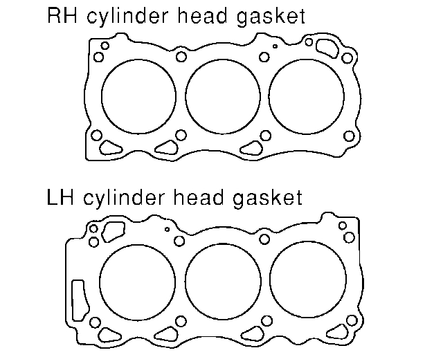
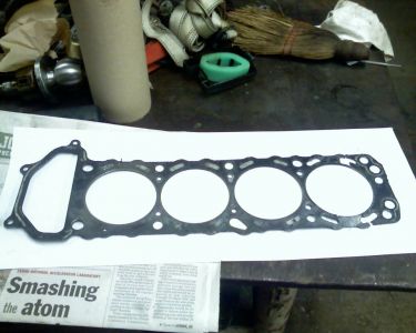
1. Install a new cylinder head gasket.
pic 29
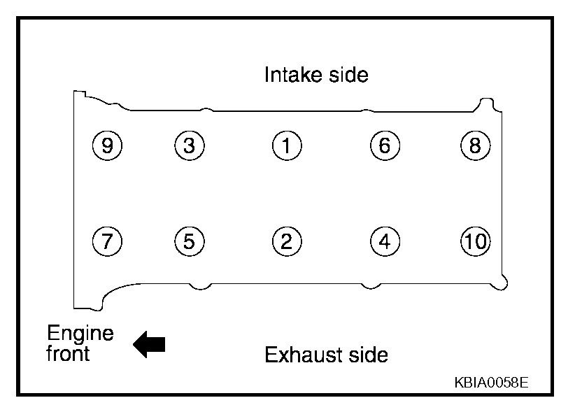
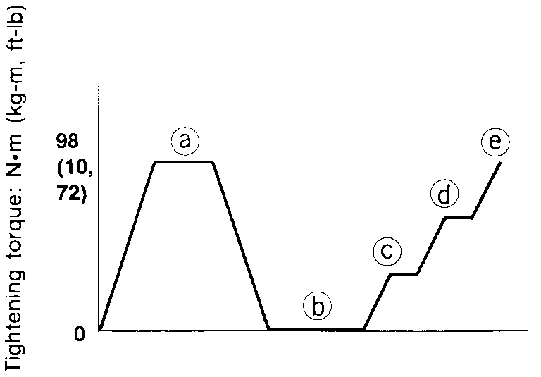
2. Follow the steps below to tighten the cylinder head bolts in the numerical order as shown.
CAUTION:
^ If cylinder head bolts are re-used, check their outer diameters before installation. Refer to "Outer Diameter of Cylinder Head Bolts".
Step a: 98.1 Nm (10 kg-m, 72 ft-lb)
Step b: Loosen to 0 Nm in the reverse order of tightening.
Step c: 39.2 Nm (4.0 kg-m, 29 ft-lb)
Step d: 75° clockwise
Step e: 75° clockwise
pic 30
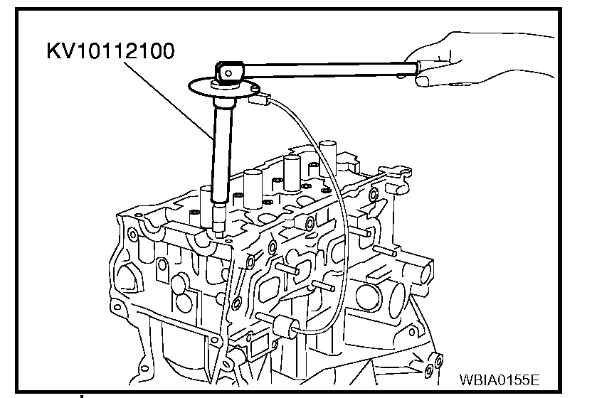
^ Apply new engine oil to the threads and the seating surfaces of bolts.
CAUTION: Check and confirm the tightening angle by using angle wrench or protractor. Avoid judgment by visual inspection without the tool.
Tool number: KV10112100 (BT-8653-A)
pic 31
3. Installation of the remaining components is in reverse order of removal.
_____________________________________________
I hope this helps. Let me know if you have other questions.
Take care and God Bless,
Joe
Images (Click to enlarge)
Feb 19, 2021 at 7:43 PM