Stereo wiring has power but no sound

Tiny
SETIGOC
  • MEMBER
  • 1998 DODGE CARAVAN
  • 4.8L
  • V6
  • 2WD
  • AUTOMATIC
  • 122,000 MILES
I hooked all the wires properly. I get power to the new after market stereo but no sound from any speakers. No wiring harness is available so I had to hard wire it. The van listed above is an LE model with infinity acoustic 10. As far as the old wires go (the following had no info on the diagram I found and aren't connected). I have 1 black wire with a dark green stripe on a plug by itself, I have 2 wires on a plug together white with black stripe and a purple. Then where the power wires come from I have 2 yellow with black stripe and an orange. Then I have the blue power antenna wire from the aftermarket. Those are not connected and can't find any info as to their purpose. Please help. If it helps here are the model numbers. Old stock radio Chrysler corporation p04704383ad, new radio boss audio 550b.
Tuesday, May 11th, 2021 AT 1:27 PM

12 Replies

Tiny
CARADIODOC
  • MECHANIC
  • 33,737 POSTS
I've worked on a number of that model radio. It is by far the highest quality radio I've ever seen. It was built by Mitsubishi for Chrysler. That's a CD / cassette combo. I sell a lot of them for upgrades when people buy used cars and want a factory CD player. Even if you don't have cassettes, it is a much better radio than the CD-only radio built by Alpine.

The Infinity system you have includes a remote amplifier. That gets its turn-on signal from the power antenna wire you listed as not connected. Without the amp, the only sound you might get is if the van has unamplified tweeters in the "A"-pillars.

With Ford and GM systems, radios that used remote amps have to be used with remote amps. Chrysler's are different. All Chrysler radios will run speakers directly, and all Chrysler radios can work with their remote amps. The amplifiers don't increase volume or power. They only modify tone conditioning for the shape of the body. What is different is the Infinity systems put out less bass, then that is made up in the amp. If you start out with a standard radio and use the amplifier, it will have too much bass unless you turn it down all the way. Conversely, if you use an Infinity model without the remote amp, you won't have enough bass unless you turn it up all the way.

This drawing shows your old plugs. The wire colors could be different in different years, but the terminal location was the same since the early '80s. The last one on the list is for the amplifier's turn-on circuit. That wire must be connected to the "power antenna" wire on your new radio.

When downgrading to an aftermarket radio, if it doesn't sound right, the amp will have to be bypassed. There might be an aftermarket plug to do that, otherwise you'll have to cut and splice the input and output wires together. With the old radio, and usually with aftermarket radios, none of the speakers wires can be grounded. There's six volts on them all the time.
Was this
answer
helpful?
Yes
No
Tuesday, May 11th, 2021 AT 5:28 PM
Tiny
SETIGOC
  • MEMBER
  • 8 POSTS
So the ground is a back strap the bolted into the back where the antenna plugs in. I wired that to the ground wire on the new stereo. I figured out the black and green wire (as per the amp label on the plug) is the amp wire. I wired that to the blue wire and still nothing. Also, I bought the new stereo because I'm sick of the static from the Bluetooth transmitter I have. The old one doesn't even have a aux port and I don't listen to the radio. My music is on my phone, I'm not even going to use the CD player. If I'm wrong please correct my error.
Was this
answer
helpful?
Yes
No
Tuesday, May 11th, 2021 AT 5:59 PM
Tiny
SETIGOC
  • MEMBER
  • 8 POSTS
I'll try that other wire later. But what's with the 2 identical yellow/black stripe wires?
Was this
answer
helpful?
Yes
No
Tuesday, May 11th, 2021 AT 6:34 PM
Tiny
CARADIODOC
  • MECHANIC
  • 33,737 POSTS
I can't speak to wire colors for sure, so I can only go by their locations in the plug. There's eight speaker wires on the old radio, and the same on almost all new radios. One is from the tail lights to tell the display to dim. One is from the dash lights to tell the display how much to dim. Those two are usually not used with aftermarket radios. Two 12-volt wires. One constant for memory and one switched. Other than those two for the display, those should all have matching wires on your new radio. The "muting" wire was only used for the talking instrument clusters in the early '90s. That just leaves the 12-volt switched wire for the amp's turn-on signal, as I mentioned previously. That one will have 12 volts on it when the ignition switch is on and the radio is turned on.

The only other point of confusion is there's no ground wire in those plugs. Your new radio might work with the ground that's the shield as part of the antenna cable, when it's plugged in, but that is not a good ground to rely on. The original radio had either a braided ground strap bolted to the back of the case, or a black wire clipped to a terminal on the back. Your new radio will likely have its own ground wire, but you can also attach the original strap or wire right to the case.

The blue wire you mentioned should be labeled for the power antenna or amp. If you still don't have any sound, check that wire for 12 volts. If it's there, the amp should be turning on.

Also be sure there's 12 volts on two power wires. All radio models act differently if the 12-volt memory circuit is missing. Some are totally dead. Some play fine but lose their station presets and clock when turned off. Some appear to work and tune normally but have no sound. If the 12-volt memory circuit is dead, that is tied in with the interior lights fuse.
Was this
answer
helpful?
Yes
No
Tuesday, May 11th, 2021 AT 6:55 PM
Tiny
CARADIODOC
  • MECHANIC
  • 33,737 POSTS
Where are you finding those two yellow / black wires? Black / yellow was the standard for the tail lights since the early '80s, but there was always just one in the radio plug. I don't recall ever seeing any yellow wires.
Was this
answer
helpful?
Yes
No
Tuesday, May 11th, 2021 AT 6:59 PM
Tiny
SETIGOC
  • MEMBER
  • 8 POSTS
According to the diagram I got the positive speaker wires are on the same plug as the switch and constant power wires as well as the black ground. That's where they are along with the unused orange wire. It's weird, the speaker negative wires are on one plug and the positive wires on the other on the old one.
Was this
answer
helpful?
Yes
No
Tuesday, May 11th, 2021 AT 9:02 PM
Tiny
SETIGOC
  • MEMBER
  • 8 POSTS
I'd post an image but it says file type not allowed.
Was this
answer
helpful?
Yes
No
Tuesday, May 11th, 2021 AT 9:04 PM
Tiny
SETIGOC
  • MEMBER
  • 8 POSTS
Just discovered my gauge lights aren't functioning now. Running lights and internal light fine but gauge lights not working. Might be a fuse blown. Not sure if that has to do with the radio though. Any thoughts?
Was this
answer
helpful?
Yes
No
Wednesday, May 12th, 2021 AT 12:29 AM
Tiny
CARADIODOC
  • MECHANIC
  • 33,737 POSTS
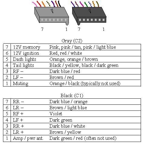
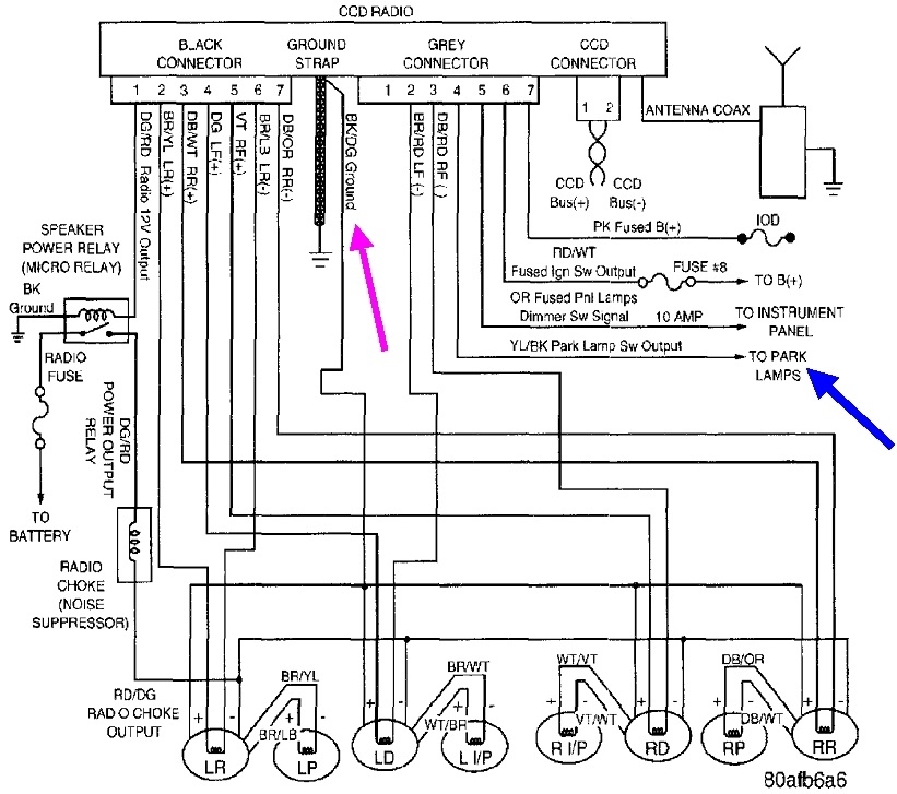
I think you just listed the problem. You used the yellow / black wire for the ground. I mentioned previously there is no ground wire in those two plugs. You have to use the braided strap that's bolted on the back, or the ground wire that's clipped onto a terminal on the back. The wire you used is for the tail lights. When you turn on the head lights at night, 12 volts shows up on that wire to tell the display to dim. By connecting it to your new radio's ground, the tail light wire is shorted to ground through the outer shield on the antenna cable.

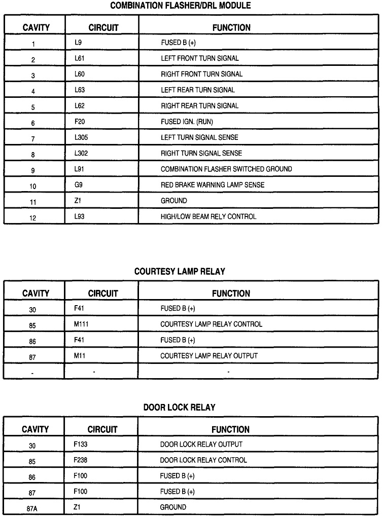
I see where you found that yellow / black wire. It's shown on this first diagram. This is the wire I drew as the black / yellow wire, but as I said, the colors can change from year to year.

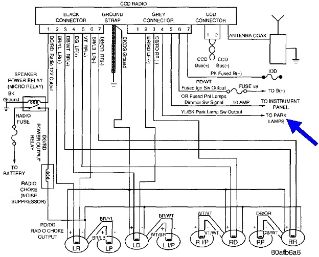
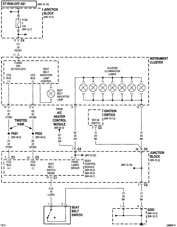
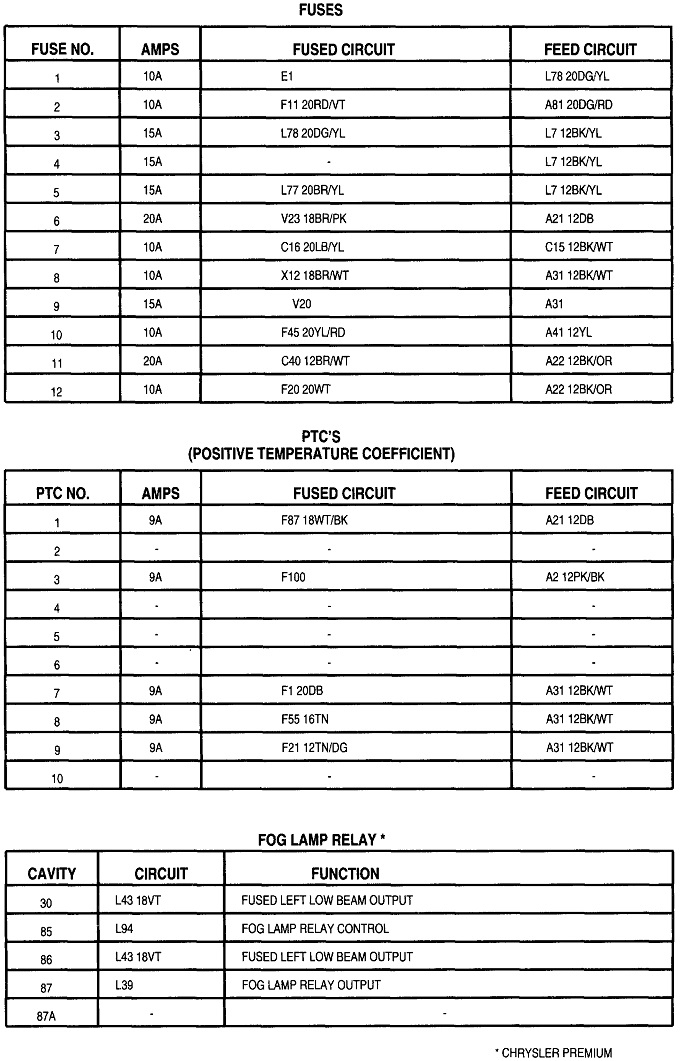
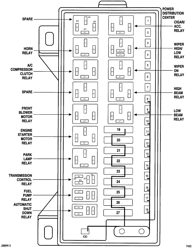
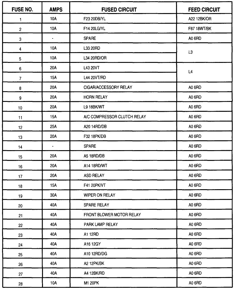
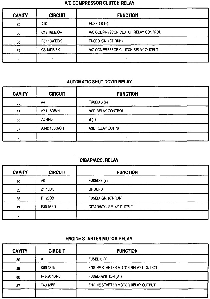
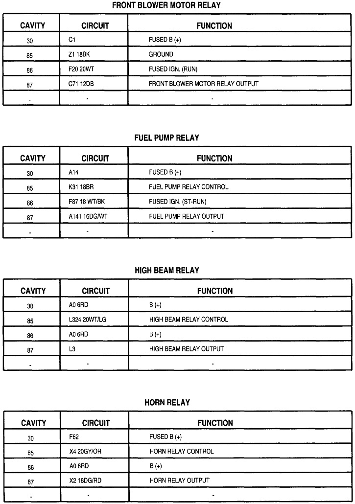
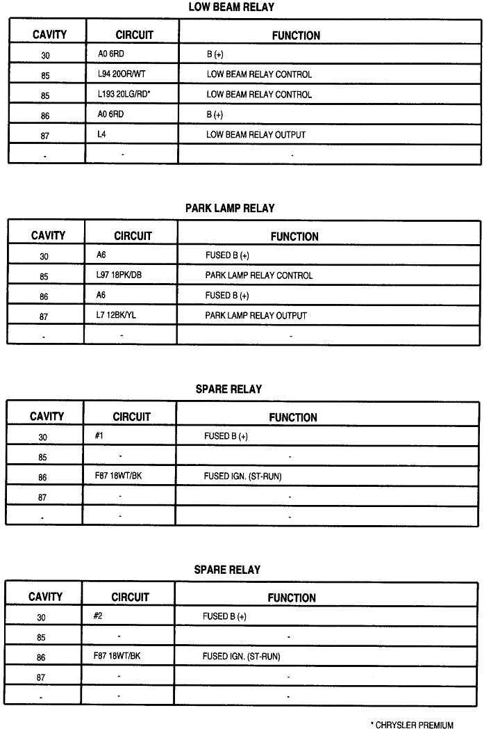
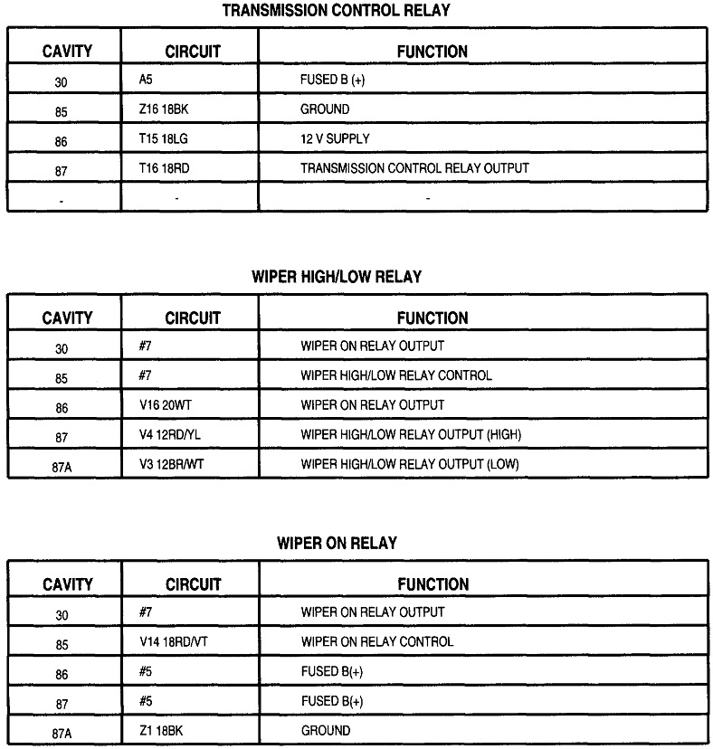
The second diagram shows the dash lights. As for blown fuses, I don't see any dedicated just for the instrument cluster lights, but I think I know why they're dead. For reference, the third through seventh drawings are for the Junction Box. That's the inside fuse box in front of the brake pedal. Drawings 8 through 13 are for the Power Distribution Center, (PDC). That's the fuse box under the hood.

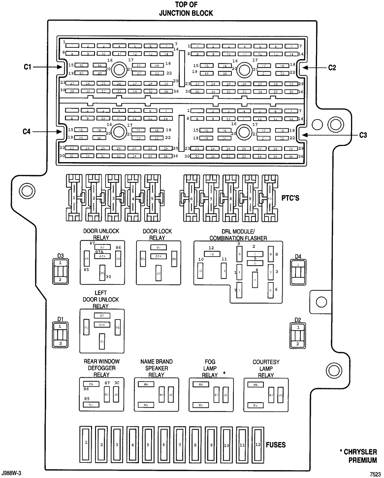
Starting with the '96 models, Chrysler started using a two-terminal semiconductor circuit breaker called a "positive temperature coefficient", or "PTC". They have a current rating like a fuse, but the instant current exceeds that rating, the device instantly goes open circuit, the same as if a fuse were to blow. The difference is when the short is removed, it goes right back to acting like a piece of wire and the circuit goes back to working normally.

There's also a lot of stuff being run by a Body Computer. On some circuits, if they detect a short, they won't turn that circuit on.

The first thing to do is disconnect the yellow / black wire and cap the end of it. That wire, and the orange wire, aren't used with aftermarket radios. Now check if the instrument cluster lights are working. If they are, they are protected by a PTC, so no further repairs are needed for that problem. If they still aren't working, start by checking the lower row of fuses in the Junction block. To make that easier, they all have two small holes on top for test points. Use a test light to check each test point. Here's links to articles that explain this better, if you need it:

https://www.2carpros.com/articles/how-to-use-a-test-light-circuit-tester

https://www.2carpros.com/articles/how-to-check-a-car-fuse

If you find 12 volts on both sides of a fuse, that one is okay. If you find 0 volts on both sides, that circuit is turned off. The lights have to be turned on during this test. You're looking for any fuse that has 12 volts on one side and 0 volts on the other test point.

As for your problem uploading images, I copy and paste them into the MS Word typing program where I can add arrows and callouts. Once all the additions are grouped together, I copy and paste that into the MS Paint program. When you go to save it, you can open a drop-down menu to select to save it as a "JPEG" file. That format, and I think one of the other formats can be uploaded. I can walk you through that if necessary.
Was this
answer
helpful?
Yes
No
Wednesday, May 12th, 2021 AT 6:27 PM
Tiny
CARADIODOC
  • MECHANIC
  • 33,737 POSTS
Looking at this diagram jogged my memory. Rather than using a remote amplifier, the minivans used very expensive speakers with little amplifiers built onto them. You'll see they have four wires in their connectors. Besides the two speaker wires, there's a 12-volt supply and a ground wire to run those amps. Where the "12-volt output" wire in the black plug provides the turn-on signal for the remote amplifier, here it turns on a relay that switches the 12 volts on for the speakers.

This diagram is not from Chrysler and at first is confusing. It looks like they're sending 12 volts from the relay to the ground terminals on the speakers. It took me a minute to realize they're showing the plus and minus symbols for the two speaker wires, not the power and ground wires. Technically there aren't positive and negative speaker wires. They're both basically the same. They just use the plus and minus signs to be sure they're wired the same so they're all "in phase". That means when one speaker cone is moving out, they all are at that time, and when one is vibrating in, they all are again. If one or more are wired "out-of-phase" you and I are never going to tell the difference. It's the placement of those polarity signs that confuse the issue because you can't tell at first which wires they're for.

The other thing I overlooked is all the speakers' ground wires are spliced together, then they go back to the case of the original radio, then to ground through the braided strap. I added the purple arrow to show that ground wire. If you forget to connect that wire to the metal case of your new radio, you'll have very little sound.

You'll notice they show eight speakers at the bottom of this diagram, but in the van you'll only find four. The tweeters are mounted onto the front of the main speakers. The amplifiers only run the main speakers. The two speaker wires pass through the amp to the tweeters. Being not powered, or amplified, if the 12 volts or ground are missing, the amps won't work, but you'll still get sound from the tweeters. Often you have to listen very carefully to hear them.
Was this
answer
helpful?
Yes
No
Wednesday, May 12th, 2021 AT 6:59 PM
Tiny
SETIGOC
  • MEMBER
  • 8 POSTS
I downloaded the diagram. But I'm very confused. It will take time to figure it out.
Was this
answer
helpful?
Yes
No
Wednesday, May 12th, 2021 AT 9:52 PM
Tiny
CARADIODOC
  • MECHANIC
  • 33,737 POSTS
Basically it sounds like you wired up the eight speaker wires and the two power wires to your new radio, but these speakers also need their own ground and power wires. That ground wire clipped onto the back of the old radio. It doesn't matter how you do it, but that wire has to be grounded all the time. The easiest is to attach it to one of the screws on the new radio's case. You had it connected to the tail light wire.

The 12-volt feed for the amps on the speakers has to be switched on and off along with the radio so they don't drain the battery when the ignition switch is off. That's the purpose of the "power antenna/amp" wire coming out of the new radio.
Was this
answer
helpful?
Yes
No
Thursday, May 13th, 2021 AT 5:22 PM

Please login or register to post a reply.

Sponsored links