No voltage to fuel pump and no reverse

Tiny
TONYRCL
  • MEMBER
  • 1994 DODGE CARAVAN
  • 3.3L
  • 6 CYL
  • FWD
  • AUTOMATIC
  • 125,000 MILES
1yr ago, tried to start the Caravan that had sat for a couple of years without being started. For diagnostic reasons that I can't remember now, but which I'm pretty sure involved introducing gas directly into fuel rail (using an OTC air pressured canister) and getting van to start, I replaced the fuel pump. Van then started a couple of times over a few days and then wld not start again. Now, a year later and after more diagnostics done, have determined that a.) No power is getting to fuel pump when relays are plugged in (except for quick 12 burst); b.) Replacement pump does not respond when relays are by-passed and power is present at the connector near the pump, so possibly whatever caused the first pump to fail also fried the replacement one; c.) Confirmed that fuel pump and ASD relays are working to the extent that the electromagnets inside do switch over the load side of the relay when there is at least 9v present, but not when it drops below that level; d.) When cranking, the engine voltage drops to below 9 volts after a quick 12v spike, the latter which I now understand (from reading caradiodoc's other posts) is normal until the engine starts running. However, what I don't know is if the voltage is supposed to return to close to the 12 volts after the engine starts. I presume that it cannot be normal to drop as much as it does for me. So it seems that the reason for the lack of power to the pump is that the relays are not switching on the load side because they are getting voltage at the Power Distribution Center that is less than the 9v+ required to energize the electromagnet inside.

Additionally, now the van will not go into reverse. Nothing happens (no jerks, no noises) when in reverse other than the back-up lights come on. Forward drive may be slow in reacting as well, but it does kick in. This new problem occurred on a very cold day after a prolong cold spell of single digits temperatures. Could temperature have been a factor?

Finally, the van has a new coil, new plugs, new plug wires, and a fairly new, but possibly dying battery (not sure if it is holding a charge as well as it should). As I said, the van starts if I by-pass the fuel pump and run it off gas being fed directly into the fuel rail. And speaking of being able to start it, what I have not tested (bc it just occurred to me!) Is to see what the voltage at the PDC is on the electromagnet side of the relays once the engine is actually running - that is, is it between the 9v and 12v needed to energize the relay or below that threshold.

So, what could be causing the voltage drain at the PDC that is failing to activate the relays? A sensor failure elsewhere, the computer, a short somewhere? I have a new Bosch fuel pump waiting in the wings to replace the apparent faulty one, but I do not want to do so until I can ensure there are no shorts or some other fault that may have fried the first two. Any help in troubleshooting this further would be greatly appreciated.
Sunday, January 12th, 2014 AT 11:11 PM

15 Replies

Tiny
CARADIODOC
  • MECHANIC
  • 33,738 POSTS
You didn't damage the other fuel pumps. There isn't anything you can do to hurt them. There IS a cause for repeat failures, but those failures always occur weeks apart. What you have is some other intermittent problem that we haven't identified yet.

I got confused when trying to follow your relay testing. It sounds like you have an idea of what is supposed to happen, but so I don't steer you in the wrong direction, I'm going to stick with my standard troubleshooting procedure. Instead of testing each little part of each circuit, which is too time-consuming, it should make us some progress much quicker.

First of all, you mentioned the one-second burst from the fuel pump when you turn the ignition switch to "run". If you hear that, you're done with the fuel system. The pump is working. The automatic shutdown, (ASD) relay and fuel pump relay are working, and the Engine Computer has control over them.

Second, since the engine runs on injector cleaner, we know it has spark. We're done with that system. Next is the circuit that causes 99 percent of the problems, and that's the one in common with both the ignition and fuel supply systems, the crankshaft position sensor and the camshaft position sensor. The clinker is though, those both have to be working for the Engine Computer to turn on the ASD and fuel pump relays, and to have spark.

Based on that, we're back to the fuel pump which I only guessed was working. If you don't hear the hum for one second when you turn on the ignition switch, start with that weak battery you observed. I think at this point, instead of covering all the possibilities, do some basic testing first before I wear out my fingerprints on this keyboard.

Measure the battery voltage. It will be 12.6 volts if it's fully-charged. If it's near 12.2 volts, it's okay but discharged. Charge it at a slow rate for an hour, then measure it again. Remeasure the voltage while a helper is cranking the engine. It must not drop below 9.6 volts. A good battery won't have any trouble maintaining at least 11.0 volts.

Measure the voltage to the fuel pump. You will see 12 volts for one second after turning on the ignition switch, then it will go back to 0 volts. What is important is it must come back during cranking, but the value is important too. If the voltage is too low, the pump may not start up. You will still have pressure in the fuel line from that one-second priming burst, but the engine will only run on that for a few seconds. Sometimes the pressure bleeds down and one second isn't enough time to get it up for starting. If the voltage to the pump remains too low during cranking, even if the pump runs, it will be too slowly to build the needed pressure. The clue there is the pump would quickly start up AFTER you stop cranking the engine and it's running on the injector cleaner. You may want to borrow a fuel pressure gauge from an auto parts store that rents or borrows tools so we know exactly what is happening in the fuel system. I've had mine hanging from the radio antenna on my daily driver '88 Grand Caravan for almost two years. I was chasing an intermittent problem, and now that it's solved, I like having it to look at.

To go in a different direction, you can bypass the fuel pump relay or the ASD relay. Sorry I can't remember if your van has both. I have a '95 Grand Caravan that also hasn't been started in years, but I really don't care to tunnel through the snow to look at it. Some things you can try are first, to swap the fuel pump relay with another one like it. The starter relay is a good one to use. That will tell us the contacts are okay. Next, you can pop the fuel pump relay's cover off, reinstall it that way, the squeeze the contact to make the pump run. Watch that movable contact to be sure it's clicking when you turn on the ignition switch. Instead of removing the cover from the relay, you can also bypass it by jumping terminals 30 and 87 to each other in the socket with a piece of wire.

I started going all over the place again. Do some of those tests, then holler back with your observations and we'll continue.
Was this
answer
helpful?
Yes
No
Monday, January 13th, 2014 AT 6:01 PM
Tiny
TONYRCL
  • MEMBER
  • 9 POSTS
Thank you Caradiodoc for responding. First off, I have done so many tests that I may need to redo some of them again and this time write the test and results down simply because I cannot always remember all of them and their combinations or what were the exact results and/or values! Having said that, I'll clarify a couple of the results which you brought up.

First, I have not gotten the replacement pump in the tank to make any noise or to build up any type of pressure, even when attaching a motorcycle battery (w about 10.25v on it) directly to the connector on the harness leading to the tank (next to it). This was also true when the pump received voltage from the van battery after I jumped the FP relay (see below), which is why I think the pump has failed. Thus, the "burst" I was referring to was one of voltage, not pressure, and then that was at the connector next to the tank (sorry if I was not clear). That burst was a momentary one - more of a split-second +/- 12v spike right when the key is in the ON position (if my memory serves me), but nothing when the engine is being cranked. Because of this, I have not dropped the tank again and installed the new Bosch pump. Note that I'm primarily checking for voltage to the dark green wire (pump); however, the dark blue wire (sending unit) does get continuous (I believe) voltage.

To verify that the issue was not the FP relay, I took it out and jumped the load side pins (30 & 87) on the PDC and I did get voltage at the connector on the harness by the tank when I cranked the engine. The caveat with that is that I do not remember the voltage or how consistent it was, nor if I also had the ASD relay out and the pins jumped when I got the voltage (Done too many combinations of tests!). However, being that, if I'm not mistaken, the load side of the relay always has power present (or at least when the engine is cranked/running) and it's the relay that switches the load connection on/off (like a house light switch), then for the purposes of the above test, whether the ASD relay was in or not might be irrelevant since I did get voltage at the pump. Where it might come in to play, I'm guessing, is if the computer recognizes the ASD relay missing (or not working) based on the control side circuit remaining open even after voltage is applied to it, and/or that control side circuit feeds something else downstream of the relay - something which is needed to start the engine. But, then again, if either of the latter two were indeed factors, wouldn't it make sense that the van would then NOT start even when I by-pass the fuel pump by injecting gas directly into the rail!

You touched on the crankshaft and camshaft sensors. Initially, I thought that if one or both were not working that the computer would not send power to the coil for a spark. However, is it possible that all the computer needs to turn on the coil is a quick "confirmation" that the one or both of the ASD & FP relays (control side) work even momentarily, and, further, that once it gets that quick response it ignores the state of the control-side of the relays' circuits? That might explain why I can still start the engine without the fuel pump working. To bolster that theory, I have confirmed that momentary surge of voltage (+/- 12v) on the control side of both relays when cranking the engine, The caveat here is that the voltage only lasts for a short period, dropping almost immediately to below the 9v threshold that the relays need to switch on (see attached chart image, which shows voltages measured on both the control & load sides of both relays under various conditions). So, if the normal engine electrical design is such that both relays (or at least the FP relay, of course) should remain powered (and therefore load side switched on) once the engine is running, then the question is why the voltage on both, but particularly the FP relay, drops so significantly and below the 9v threshold.

Anyhow, I will charge the battery again tonight and perform both my tests and the ones you suggested tomorrow. Thanks and stay tuned.
Was this
answer
helpful?
Yes
No
Monday, January 13th, 2014 AT 10:48 PM
Tiny
TONYRCL
  • MEMBER
  • 9 POSTS
P.S. A couple of corrections: First, on the 3rd paragraph of my last response, I meant to say that I was verifying that there wasn't a broken connection in PDC or in the harness down to the fuel pump (well, at least to the connector near the tank). Second, the chart is incorrect in that I had no voltage on the control side of the FP relay pins when the key was off. Corrected chart is attached.
Was this
answer
helpful?
Yes
No
+1
Monday, January 13th, 2014 AT 10:59 PM
Tiny
CARADIODOC
  • MECHANIC
  • 33,738 POSTS
One thing that I think is going to give more accuracy is if you can use a test light instead of a voltmeter. When you get back to the pump connector, I never paid any attention to the voltage, just whether it was there or not. If there is a high-resistance break in that wire, all it takes is a tiny spot of corrosion or a little carbon track to conduct enough current that the voltmeter will detect the voltage, but obviously that's not enough current to run the pump. A test light needs a lot more current to operate and will not light up if there's a break in that wire.

The alternative is to measure the voltage on that wire while it's still plugged in and the pump is drawing current, but that's not easy to do unless you can fashion a piece of wire for a test point.

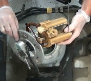
The pump still should have run with an external battery.

Oops. Let me back up for a minute. When you turn on the ignition switch, you already heard those relays get powered for one second. That is done to run the fuel pump in case the pressure bled off overnight. I don't know about the 3.3L, but I do know from chasing an intermittent problem on my '88 with the 3.0L, that both engines run around 50 pounds of pressure, but my 3.0L still runs fine down to 20 pounds. (Some GM engines won't start if pressure is just two pounds low).

Once you start cranking the engine, pulses arrive from the cam and crank sensors. That is how the computer knows the engine is rotating, (cranking or running), and that is when it turns on those two relays. The fuel pump relay feeds only the fuel pump. The ASD relay feeds the ignition coil, or coil pack in your case, injectors, alternator field, oxygen sensor heaters, AND the fuel pump on older vehicles without a separate fuel pump relay. This is a safety circuit and it's real effective and reliable. If the vehicle is in a crash that ruptures a fuel line, raw fuel will get pumped onto the ground, and some people seem to think that's a fire hazard. The injectors can't spray fuel with no fuel pressure in that ruptured hose, so the engine stalls. When it stalls, there's no more pulses from the two sensors so the computer turns the ASD relay, (and the fuel pump relay) off. That stops the gas from being dumped on the ground.

I don't recall the computer monitoring the coil part of those two relays. It just grounds one terminal and assumes they turned on. There IS, however, another circuit coming off the ASD relay that, along with feeding the injectors and coil pack, goes back to a terminal at the computer. If no voltage shows up there, the computer can set a fault code related to the ASD relay not turning on, or that voltage is missing, or something like that. That circuit might supply other things inside the computer but it has nothing to do with the engine not running.

On the newer engines, as a point of interest, the engine will continue to run if one of the two sensors fails, but once it is stopped, it will crank but not restart. (There is a way to trick it into starting and running), but on this one the engine will stall if either signal is missing. The fact that the engine runs proves there's spark and the injectors are firing. That proves they're getting current from the ASD relay, so we know the computer is turning it on and the two sensors are working.

That brings us back to the fuel pump. GM pumps commonly fail while you're driving, leaving you sitting in the middle of nowhere on the side of the road. Chrysler pumps rarely if ever fail once they've started to run. They typically fail to start up. There's two causes for that. Most commonly, at high mileage, the brushes in the motor wear down and don't make good contact. The clues are that often a bang on the gas tank gets them going, you don't hear the hum for that one-second burst, and if you jump the relay or squeeze its contact, you won't see the normal tiny spark when you open the circuit. That's because there's no current flow, hence, no spark when you turn it off.

The second cause, which I eluded to earlier, has to do with repeat failures, usually from a week to a month apart. Many people buy a replacement pump from an auto parts store, and it works fine for a few weeks, then fails to start up. After four or five failures, out of frustration, they buy one from the dealer and don't have any more problems. In reality, the pumps weren't the problem. Unlike GM truck fuel pumps that you can hear a mile away, Chrysler pumps are built to very close tolerances to make them really quiet. Microscopic debris collects in the tank, (I suspect mold growth from using ethanol), and that debris clogs the impeller which locks up the motor. Each replacement pump collects a little more of that debris until finally it's all gone and the next pump won't fail. That one just happens to be from the dealer. As another point of interest, NAPA buys their fuel pumps for Chrysler products from the same supplier that makes them for Chrysler, so you're getting the same pump as the dealer's pump, and they're just as quiet. That may be true of other auto parts stores too but I only know that for sure about NAPA. The clue to this problem is you WILL see a spark when you jump the fuel pump relay but it won't blow a fuse. There's obviously current flow but the motor doesn't run. The fix for this was to remove the tank and have it steam-cleaned at a radiator repair shop. I haven't heard of this happening lately, possibly due to better additives in the gas today.

Getting back to your pump, jump the relay so you don't have to turn on the ignition switch or crank the engine to do the troubleshooting. Check for voltage at the pump on the dark green / black wire. If it's missing, there's two connectors between there and the relay that are good suspects. If you DO have voltage there, check on the black ground wire. If you have any voltage on that one, there's a break in it. You may be able to get a clue from watching the fuel gauge on the dash. The sending unit shares the pump's ground wire. If the gauge reads correctly with the ignition switch on, but changes during cranking, it has to be due to voltage on the ground wire.
Was this
answer
helpful?
Yes
No
+1
Tuesday, January 14th, 2014 AT 3:35 AM
Tiny
TONYRCL
  • MEMBER
  • 9 POSTS
Thanks again. Can't do any testing today as it has been pouring buckets all day. Will try again tomorrow. I will review your comments more carefully later today, but in the interim I wanted to address your observation on the fuel gauge on the dash, which reminded me of the following.

As I stated previously, there is power on the blue wire at the connector near the tank, but not on the green wire when cranking. Yet, I did notice that the fuel gauge never worked after I replaced the pump (a unit sold by Shepherd Auto Parts or something to that effect), yet it was working with the original Chrysler pump. Although I don't remember all of the details at the moment, I did have to splice a new connector on the wiring harness at the pump bc the old one literally broke apart removing it (I salvaged an identical one off inside the old pump). However, aside from the black wire, the new pump did not have green and blue wires, only blue ones, I believe, so I had to make the best educated guess I could as to which of those blue wires lined up with the green and which with the blue on the connector from the harness (I can't remember if the old pump had any differentiation on the wires inside). Although I can't be 100% sure, I had been fairly confident I did line them up correctly. However, if I didn't, I suppose that would explain why the gauge was not working since the green wire is not getting voltage. Of course, even if I had reversed them, the pump should still pump (it did initially) since the blue wire does have voltage. What might be possible as to why the pump does not seem to work could be that one of the splices came loose somehow, breaking the connection, leading me to incorrectly believe the pump had failed (or possibly shorting the pump out). Incidentally, the new Bosch pump I have waiting to install if need be also has 2 blues and a black (it also has a red, but it does not line up with any prong on the pump's connector); so, I may be needing to do this guessing dance again!

Assuming I get some dry weather tomorrow, I will test for power using a test light as you suggested. Also, though my OBD II scan tool won't work on the van (its OBD I), I may have found a way to get fault codes out of it. If I am successful, I will pass those along. Stay tuned.
Was this
answer
helpful?
Yes
No
Tuesday, January 14th, 2014 AT 3:22 PM
Tiny
TONYRCL
  • MEMBER
  • 9 POSTS
Performed some additional tests today using the voltmeter and the test light but I was not able to do any tests on the connector near the tank using the either tool simply because I did not realize I no longer have access to that side of the van since I moved it last (not having the reverse drive working complicates matters. Will try again on Thursday when I have my kids around to help me push it back!)

What I was able to do was a couple of things: First, I took the battery out and completely cleaned all the connections down to shiny metal since there was a grayish film on the surface of the connections. The second thing I did was get the DTC’s, which came up with 12 and 55 right after reconnecting the battery, which I understand represent a normal condition, and I got equal results after cranking the engine. The third thing I did was get some voltage readings again using both a voltmeter and the test light at the PDC. The battery cleaning must have really helped since I was able to get better voltage readings at the PDC relay terminal points than I had gotten last week †particularly in the low range affecting the relay control side's 9v needed to activate them. However, I want to redo a couple of them before posting them here because they don’t make sense based on my earlier tests and I need to verify I didn't miscopy (is that a word!) Something somewhere; plus I want to do the test with the test light at the connector near the pump as well.

The interesting thing in all this, however, is that after doing all those voltage readings, which involved taking the FP and ASD relays in & out and in various combinations thereof, I cranked the engine again and got a new DTC: 42... Twice! Just to be sure it wasn’t related to playing around with the relays, I disconnected the negative terminal of the battery to erase whatever codes were stored, cranked the engine once more, but got the same result: 12, 42, 42, 55. I don’t know why I got 42 twice, if it means anything, but a 42 DTC seems to be that there is a short or open circuit at the ASD relay, though I can’t confirm that since one website listed 42 having multiple meanings, including fuel pump relay circuit, no change in fuel level unit, and voltage missing when auto shutdown is energized!

Incidentally, I did test voltage at the source for each of the FP and ASD relays (pins 30 & 86) using the test light, and always got a solid light on each, but let me confirm that tomorrow.

Thanks again.
Was this
answer
helpful?
Yes
No
Wednesday, January 15th, 2014 AT 7:42 PM
Tiny
CARADIODOC
  • MECHANIC
  • 33,738 POSTS
42 - Auto shutdown (ASD) relay voltage not sensed at controller.

This is right out of the '94 service manual. The generic description from this site covers multiple years. That's why it includes the fuel pump relay with the ASD relay in the description.

If the engine runs on starting fluid, the ASD relay is working. That only leaves the wire that splices off and goes to the Engine Computer so it can verify that relay turned on. Put your test light on either smaller terminal on the back of the alternator, or the dark green / orange wire at the coil pack or any injector. You can back-probe those terminals through the rubber seals. You should see 12 volts there for one second after turning on the ignition switch, then again during engine cranking. If it's missing, try a different relay. If it's only missing during cranking, we have to look at the cam and crank sensors.

If you have voltage there, it may be not reaching the computer. That comes in on pin 57, also a dark green / orange wire. The connector is a 60-pin low-insertion plug meaning it takes no pressure to install it. You remove it by unscrewing the bolt in the middle, and you install it by just holding it in place, and running that bolt down with a small hand ratchet. Pin 57 is in the bottom row of pins, fourth one from the firewall end. You don't have to remove the plug. There's a plastic cover that can be snapped off to get to the terminals.
Was this
answer
helpful?
Yes
No
+1
Wednesday, January 15th, 2014 AT 8:16 PM
Tiny
TONYRCL
  • MEMBER
  • 9 POSTS
Hello Caradiodoc, I have some interesting news.I now have power on the green wire at the connector near the tank when cranking! I don't know why, since the only thing I have done is reset the computer by disconnecting the battery as well as cleaned its connections. I'm also not getting the 42 DTC anymore. However, the fuel pump still does not pump. I'm baffled, elated, and concerned all at once. I'm concerned bc I don't know if the fix is permanent or if there is a short somewhere that is going to prop its head sometime again and leave me stranded with a third damaged pump!

Notwithstanding the fix, I still conducted several tests (voltage readings and use of the test light) and their results are listed in the attached image. I also did the check at the injector and computer using the test light. I was able to get voltage at the injector, but not at the computer or its connector (not knowing which way the power flowed, I tested both of them). I don't know if my test light probe was too thick for the connector to get a reading, or if there is still a problem somewhere.

Incidentally, I confirmed power at the wire harness connector with the test light as well, which also showed that the blue wire had a low amperage since the light came one very dimly. I can imagine this might be by design since it's feeding only the sending unit, but I don't have a service manual to confirm. Do you think that is a problem? Furthermore, whether the low amperage is by design or not, if I somehow crossed the green and blue wires at the pump connector, if might explain why the pump does not pump. The caveat with that theory is that I again tested the pump by connecting it directly (well via the connector) to a 10.5v battery and I never heard any noises, so it's either very, very quiet, there's a break at the connector at the pump itself, or it is indeed fried.

I don't know when I will get a chance to drop the tank again to replace the pump and test the current one or replace it if need be. In the interim, besides any additional info you could provide on this on/off voltage issue, can you provide any suggestions on what could be causing the van not to shift into reverse?
Was this
answer
helpful?
Yes
No
Thursday, January 16th, 2014 AT 8:23 PM
Tiny
CARADIODOC
  • MECHANIC
  • 33,738 POSTS
First of all, I'm not an expert on the electronic part of the transmission, so I'll just think on that for now. Second, I get the feeling you may not have a clear understanding of electrical theory. If I'm wrong, forgive me, but to be safe, allow me to clarify a few points that ARE confusing to most people. Voltage is electrical pressure and it can be compared to water or air pressure in a pipe. Current is electrical flow, just like, ... Uhm, ... Flow in a water pipe or compressed air line. Direction of that flow depends on where the higher and lower pressures are. "Power" is a legitimate term, and is simply the volts times the amps in a circuit, but it is always used incorrectly in conversations. And for the biggee, there is no "juice" in electrical circuits. I always told my students they could use that term on only the first day of class until they knew better, then we would stick with correct terminology. No matter how hard we squeeze a wire, there will be no juice coming out.

You have a much better grasp of electrical theory than most people. The only thing that made me want to mention these things for the benefit of other people researching this problem and reading this was your comment about:

"I was able to get voltage at the injector, but not at the computer or its connector (not knowing which way the power flowed, I tested both of them).

Normally I would say you just need to check for voltage, and if it's there, the current flow will take care of itself, but there are too many things here pointing to a POOR connection which acts totally differently from a broken connection. That's where people with decent knowledge of electrical theory get stuck. That's also why I ask a lot of questions that would seem to have obvious answers. Besides just analyzing the results of tests I tell you to take, and arriving at a fix, my mind works best when I explain how the circuit works along the way so next time you have a better chance of finding the problem yourself.

Getting back to the important issue, you found no voltage at pin 57 of the computer. I know from working with these connectors that 99 percent of the time that is because the meter or test light probe did not make good contact with the terminal. The first thing an inexperienced mechanic or do-it-yourselfer might do is bare the wire near the connector to take a reading. That is another thing I never allowed my kids to do because we don't damage a customer's car that way, and most of the time moisture will get in there and you'll have a corroded connection in a few weeks. In this case, the best test is to remove the entire plug from the computer, the probe on the exposed terminal end to measure the resistance between that terminal and that same color wire at one of the injectors or the coil pack. Your meter leads will have a few ohms of resistance so overall, you can expect to find, ... Oh, ... Perhaps two to five ohms total. If you find considerably more than that, I'd start to be concerned there's a corroded splice. I can look in the service manual for the location of that splice.

You said that code isn't setting anymore so we might be spending too much time on something we don't need to, but if you suspect there is an intermittent problem here, a better way to test that wire is with it trying to conduct some current, as in running the test light. To do that you'll have to bypass the ASD relay since the computer won't be there to turn it on, then use the grounded test light to test for voltage at pin 57 in the connector. If the test light is dim or it flickers, wiggle around on the harness to see if anything makes it change. Your test light will draw a lot more current than the computer will, so if that wire can run the test light at full brightness, it will be working properly for the computer.

As for the wires at the fuel pump connector, current has to go through the fuel gauge circuitry in the gauge cluster, then to the sending unit in the tank. That circuitry has some resistance, just like standing on a garden hose, so the voltage at the tank will be lower. Just like that partial restriction in the hose though, you WILL have full voltage at the tank when no current is trying to flow, as in when using a voltmeter. If your nozzle on the hose is turned off, you'll have full pressure there even when you're standing on the hose. The test light allows current to flow which causes some of the 12 volts to be "dropped" across the gauge circuitry. The remaining voltage is dropped across the test light, and since that is only part of the 12 volts, the light is dim.

Once a person understands this, it's easier to see that a voltmeter measures the voltage by measuring electrical pressure, and the test light measures voltage by measuring current flow. It just takes a tiny spot of carbon or corrosion to pass enough voltage to be picked up by a voltmeter. It takes a good, solid connection to pass enough current to run a test light.

See how far you get now. My computer just started acting up again with a problem I've been fighting for two years. I have to shut it down and start over. I'll be back in about 15 minutes.
Was this
answer
helpful?
Yes
No
Friday, January 17th, 2014 AT 12:14 AM
Tiny
TONYRCL
  • MEMBER
  • 9 POSTS
I would be the first to admit that I am not an electrical expert, by any stretch of the imagination, and that probably has come through in my writing. I know enough to make me dangerous, as the saying goes, and I don't always get my terminology (maybe even electrical facts) correct!

Having said that, the reason for my statement about the testing both the computer and its harness was that it was not clear to me if I was to test the connector at the harness or the actual computer pins - that because I was not sure at that moment, nor did I take the time to see if I could figure it out, honestly, from where the source of electricity came - from pin 57 on the harness connector into the computer or vice versa; however, it sounds from the 2nd test you suggested that, on that particular wire, the "current" flows into the computer from the connector. Perhaps if I had had a complete wiring diagram with a legend I might have been able to figure it out (or not!).

In any case, I ended up taking the battery and the platform it sits on out to better inspect the wires for damage and noticed that the cloth-like wrapping surrounding the myriad of wires in that vicinity (coming off the computer and from the PDC) was missing in areas and much of it tore off quite easily. I cleaned the wires best as I could and inspected them for missing insulation or teeth marks in case a critter was the culprit for the damage to the wrapping, but I did not see any damage whatsoever to the wire jackets. I would like to do a more through check there at some point, but I will need to also pay a closer look at the ones tucked in to the right of the windshield washer reservoir near the firewall and fender.

I'll attempt to do both tests you suggested tomorrow. And thanks again for all the time you have devoted to helping with this puzzle!
Was this
answer
helpful?
Yes
No
Friday, January 17th, 2014 AT 1:21 AM
Tiny
CARADIODOC
  • MECHANIC
  • 33,738 POSTS
Dandy. I'm back now for another 15 minutes to 15 hours. Never know when my 'puter will give intermittent "not responding" messages again.

On a related note, there were some problems with the wiring harness right underneath the Engine Computer, or right next to it, on the left inner fender. That harness slides back and forth as the engine rocks during acceleration. A coworker, who was the heating and AC specialist at the dealership where I used to work, had a '94 or '95 Caravan come in with overheating issues and a burned open fuse link wire to the radiator fan motor. Obviously the motor had to be shorted so he replaced both parts and sent the owner on his way. It came back three or four times, always with the same fuse link wire burned open, and on one visit, as it was our custom to watch other mechanics' projects for burned-out lights, I pointed out he had no backup lights too. After repairing the fuse wire again, he DID have backup lights, but as soon as he accelerated to leave the shop, the lights went out, and that's when the diagnosis took a whole new turn. The fuse link wire was burned open again before the radiator fan even had time to get turned on.

My trick is to replace a blown fuse with a 12 volt light bulb, and when we put the van in "park" with the engine not running but the ignition switch on, the light bulb would get bright, indicating lots of current was trying to flow, when we rocked the van and made the engine rock and tug on that harness. Finally found a bunch of those wires laying on the inner fender had rubbed through their insulation, and the paint was rubbed off, and there was the intermittent short.

Those fuse link wires were used because they will not burn open from a nuisance momentary current spike which is typical of a motor starting up. While that "slow-blow" feature is a benefit, a carbon track is left behind where the wire burns apart, and it's that carbon track that lets just enough current trickle through that a digital voltmeter can detect something. Enough current to run a test light can not get through. That's why test lights can be more accurate in those situations. A similar thing happened to another very experienced mechanic who happened to be our transmission specialist, when he also had a tight radiator fan motor on a K-Car. He found voltage to the motor with a voltmeter, then couldn't understand why the new motor wouldn't run when it was connected to that wire. Being the smart fellow I thought I was, and the new guy, I convinced him to use a test light instead of the voltmeter, and then he did not have any voltage there. Just needed a new fuse link wire.

Anyway, now that I'm done tooting my own horn, I'll wait for your next set of test results and we'll continue on.
Was this
answer
helpful?
Yes
No
+1
Friday, January 17th, 2014 AT 1:59 AM
Tiny
TONYRCL
  • MEMBER
  • 9 POSTS
No. Using the test light is definitely a great idea, as I had forgotten that getting voltage and the right amount of current [ amps? Or is it "juice"? :) ] Are two different things.

I have not been able to do the resistance and other tests that you suggested and I may not be able to do them now for several days due to business travel demands, but I will do so as soon as I can and get back to you afterwards. However, I did have a few minutes free today and I made a closer inspection of the wires next to the windshield washer reservoir, which are coming off the PDC and into the firewall (I think), and I did find some wires with damage to their insulation (likely from critters), which had been taped over (I must have suspected something at some point in the past and had my son do a quick patching up, but I can't remember).

Though it's possible that these sections of wires need to be replaced completely, not just taped up, and that this could be the source of any intermittent shorts that may be occurring, after reading about the issue you had with the other harness rubbing and causing a short when the engine is running, I'm more apt to think that something like that could be the cause of the problem I'm experiencing, since it was after I ran the engine that the 2nd pump failed and that I stopped getting voltage to the pump. Though having "reset" the computer by unplugging the battery could have been the fix, it's also possible that one of the many times I cranked the engine, it moved any wire shorting out on the chassis enough so that it resolved the DTC 42 and also stopped the computer from cutting off power to the ASD relay when cranking (!)

In any case, it looks like I'm in for a long 2-3 days of testing and/or splicing new wires on that entire grouping by the PDC. I'll also need to check the others on the left side of the engine as you mentioned. Incidentally, if you have access to a complete wiring diagram, would it be possible to send me a copy or post it here? That would be very helpful!

By the way, what exactly does a "fuse link" on a car look like, and where are they on my specific model van? (I have searched for picture online, but without success).
Was this
answer
helpful?
Yes
No
Saturday, January 18th, 2014 AT 5:25 PM
Tiny
CARADIODOC
  • MECHANIC
  • 33,738 POSTS
I have the wiring diagram in the Chrysler service manual but it covers over 200 pages. Your best best to find one is on eBay. The '93 and '95 diagrams will be real close too. You might also check at a nearby community college that has an Automotive program. We had AllData on four computers in the shop and one in the library that was available to taxpayers. You can get a subscription to AllData or Mitchell On Demand on the internet too, but I hate diagrams on computer, and I refuse to rent the service. I only buy paper service manuals to keep that I can put notes in and find things quickly.

If you've never used a Chrysler wiring diagram before, be aware you'll be bouncing around a lot of different pages based on the "sheet" numbers on the bottom, not the page number in the book.

Fuse link wires are smaller in diameter than the wires they protect. They're about 8" long and will be in a bundle going around the left strut tower. You tug on them to test them. If they're good, they'll act like a wire. If they're burned open, they'll act like a rubber band. That break is where a carbon track will form. You can find the two ends of a link that's burned open and splice them together, then seal it with heat-shrink tubing with hot-melt glue inside. That is what was used originally. You can also buy new fuse links from any auto parts store. One piece is long enough to do two or three repairs. You buy new fuse link wires by gauge and color. Don't use regular wire for the replacement. The insulation on fuse link wires is designed to not burn or melt.

Don't use electrical tape either anywhere on a car. It will unravel into a gooey mess on a hot day.
Was this
answer
helpful?
Yes
No
Sunday, January 19th, 2014 AT 1:38 AM
Tiny
TONYRCL
  • MEMBER
  • 9 POSTS
I had some time to spare today and performed a few of the tests you suggested. First the resistance between the computer connector and the fuel injectors (tested 2) was 0.4 ohms, which of course is meaningless without knowing what the maximum resistance should be. Also, having jumped the switch/load side of the ASD relay connector, I got no voltage readings at pin 57 on the computer when cranking, which, unless I was supposed to jump the control side of the relay instead (?), Seems to me to not make sense since I've proven the van will start (and that pin is sending voltage to the injectors, correct?). Not sure what this all means, but perhaps you will be able to shed some light on it.
Was this
answer
helpful?
Yes
No
Sunday, January 19th, 2014 AT 10:34 PM
Tiny
CARADIODOC
  • MECHANIC
  • 33,738 POSTS
All you're looking for at pin 57 is if you have something or nothing. I suspect the code related to that pin was set earlier when you had the ASD relay out.
Was this
answer
helpful?
Yes
No
Sunday, January 19th, 2014 AT 11:44 PM

Please login or register to post a reply.

Sponsored links