No start condition, P0118 and P0343 codes

Tiny
RGRUBER69
  • MEMBER
  • 2003 CADILLAC CTS
  • 3.2L
  • 6 CYL
  • 2WD
  • AUTOMATIC
  • 168,000 MILES
Replaced thermostat, coolant temperature sensor. Took for test drive and ran good, came home and checked coolant, filled some more. When looking a saw the cam sensor wires were taped together. I jiggled them and the car stalled. Wouldn't start after. Replace cam position sensor, reset ECM and the car started, but was hard to start. I drove about 5 minutes and came home. It was rough at first until warmed up then ran fine. Turned it off at home, now will not start. Cranks but doesn't fire. Checked codes, under pending I have p0118 coolant temperature sensor high circuit and p0343 cam position sensor high circuit. Live data on my little scanner shows -40 on the coolant sensor. Checked all wires, nothing pinched or broken that I can see. Now I'm stumped and frustrated. Please help!
Tuesday, April 14th, 2020 AT 6:34 PM

32 Replies

Tiny
KASEKENNY
  • MECHANIC
  • 18,907 POSTS
Have you repaired the wires that were taped? The -40 is an indication that you have an open circuit. That is a default when either the sensor is open or the wiring to the control module. I attached the testing for the ECT code. Pay close attention on step 6 assuming you don't repair it in a prior step. However, I suspect you have a 5 volt reference issue.

I also included the Cam code but I would start with the ECT temperature code and see what you find. I included the wiring diagram as well. As you will see the cam sensor and ECT share a low reference wire which is spliced together. That is the 5 volt reference wire which I suspect is your issue.

Let me know and we can go from there. Thanks
Was this
answer
helpful?
Yes
No
Tuesday, April 14th, 2020 AT 7:04 PM
Tiny
JACOBANDNICKOLAS
  • MECHANIC
  • 108,170 POSTS
Hi,

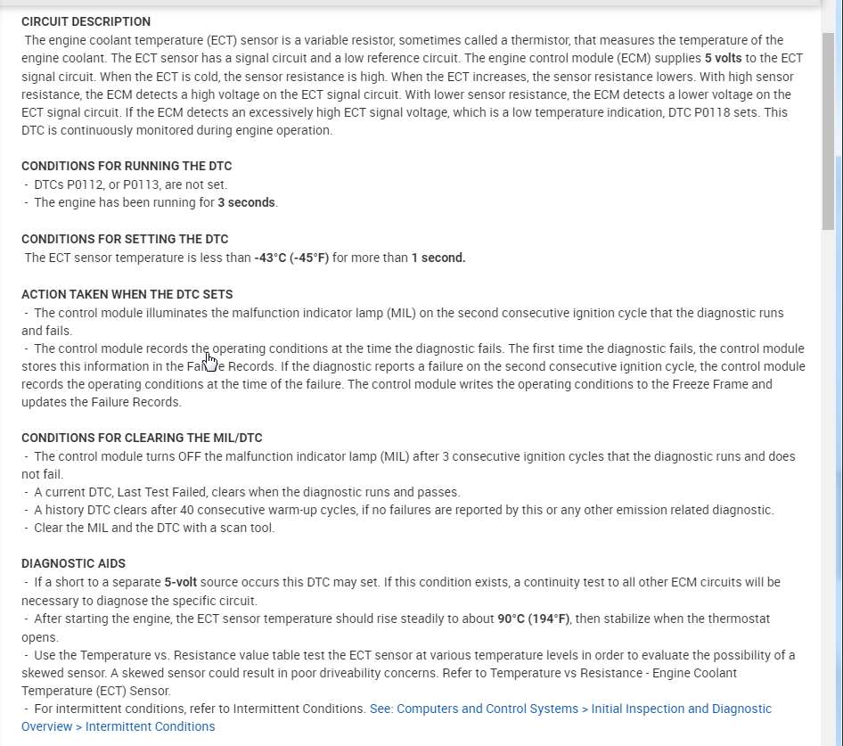
The coolant temperature sensor is the likely cause of the no start. If it is indicating -40° F, it's dumping fuel to the engine to run in extreme cold temperatures.

Now, anytime I have had this happen, the sensor was bad. However, you indicated the sensor was replaced. So, we need to check it to determine if the sensor is bad or there is excessive resistance in the wiring to it, or the plug itself.

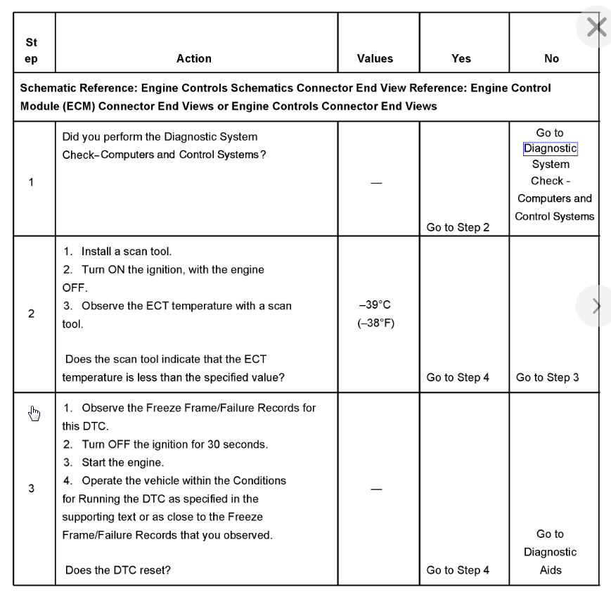
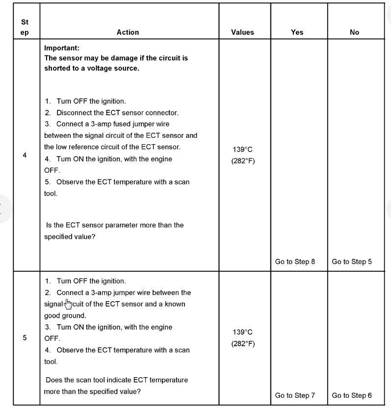
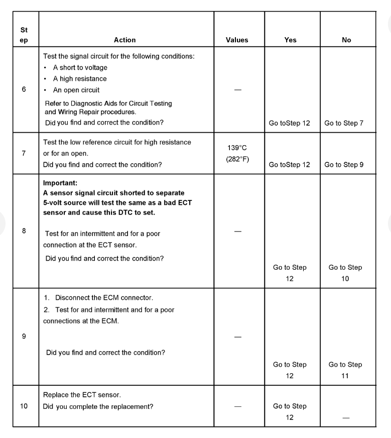
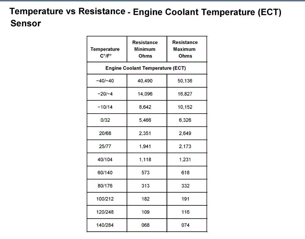
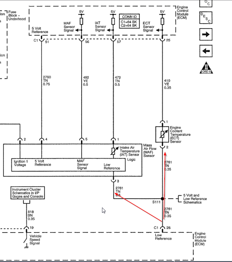
If you look at the attached pic, it shows what the resistance should be based on temp. Before going crazy and testing it, reconfirm there is no wiring damage and the connector is tight, clean, and there is no damage to the connector.

https://www.2carpros.com/articles/how-to-use-a-voltmeter

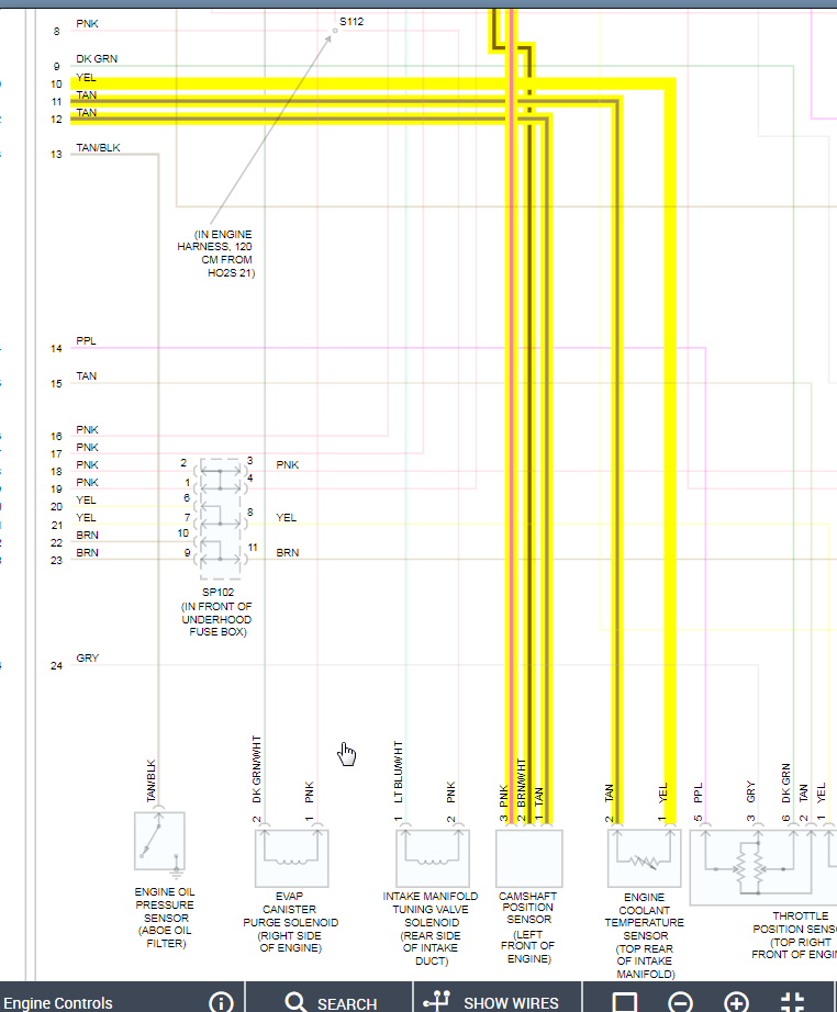
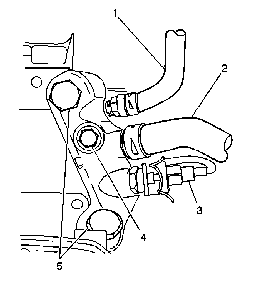
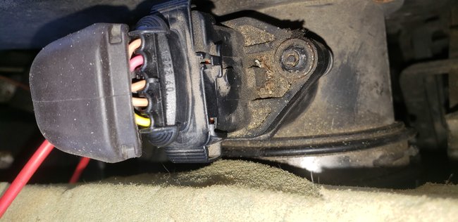
Also, just to confirm we are referring to the same part, it is located in the crossover pipe. See pic 2

Because of the sensor's location, I hate to say it, but it will be easier to remove it for checking unless you can access it to check resistance.

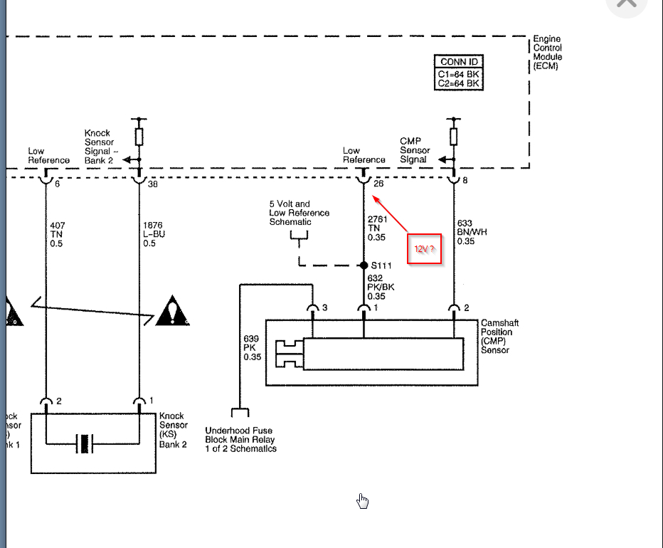
The only other thing I'm concerned about is the connection at the cam sensor. You indicated it was taped. Make sure that everything is properly put back together and shielded.

To shed some light on my rational for the not running condition is simple. You have two codes. From experience, I know if the ECT is indicating -40, either the engine will not start or be running extremely rich if the ambient temp isn't as indicated. If you pull a plug after trying to start it, chances are it will be wet with fuel. Now as far as the cam sensor code, the reason I don't feel that is causing a no start condition is because the system is designed to still run in a default mode even if the crank sensor fails. The only thing that will cause a no start related to the cam sensor would be if there was no crankshaft position sensor signal. Then it wouldn't run. An easy way to check for a crank signal is simple. Using your live data scanner, see if there is an RPM signal when cranking the engine. If there isn't one, chances are the crankshaft position sensor has failed. If you can't read an RPM signal, check to see if there is spark to the plugs.

Here is a link that shows how to check for spark:

https://www.2carpros.com/articles/how-to-test-an-ignition-system

________________________________________________

Okay, I hope this all makes sense. Let me know what you find or if you have other questions. I'll be here.

Take care,
Joe

Was this
answer
helpful?
Yes
No
Tuesday, April 14th, 2020 AT 7:14 PM
Tiny
RGRUBER69
  • MEMBER
  • 22 POSTS
Kasekenny, with both sensors sharing a common ref wire, can I assume that there should be continuity between the two? And are those the only two sensors to share that common wire? And on the sensor wires, should I check for 5v on the tan wire? Before treating into the entire wire harness, I'd like to isolate smaller sections to check!
Jacobandnickolas, I did replace the cam sensor that had the taped wires, but an currently trying to chase the remaining wires for damage. I'm hoping it didn't short the ECM! As far as my little scanner, it shows approx 750 rpm's at cranking, so I'm assuming crankshaft sensor is okay!
Was this
answer
helpful?
Yes
No
Wednesday, April 15th, 2020 AT 4:54 AM
Tiny
KASEKENNY
  • MECHANIC
  • 18,907 POSTS
Yes. They will have continuity but you want to check end to end. Meaning from the module to the component. Clearly when there is a splice you will have continuity from the module to multiple sensors.

If you have 5 volts coming out of the module, you can just run a new wire to each sensor. In essence you splice in a new wire and run it directly to the sensor and replace the wire that is at the sensor. Due to this being a splice for multiple sensors you don't want to eliminate the current wiring or you will lose the 5 volt reference to the other sensors. You just want to replace the wires that have the issue. This way you don't need to do an entire harness. Does that make sense?
Was this
answer
helpful?
Yes
No
Wednesday, April 15th, 2020 AT 7:48 AM
Tiny
RGRUBER69
  • MEMBER
  • 22 POSTS
Kasekenny1, let me see if I follow you! If my ECM is putting out 5v, I can tap into that wire at the ECM and run new to each sensor affected. Since there's only 2 sensors affected, I would cut the tan wire at each sensor harness and run a new wire from ECM to each sensor harness. That would leave me with 2 splice points, the original s111 to all other sensors, and the new splice point I created for the affected sensors.
How many sensors actually share that same tan wire? Coolant and cam for sure, I'm thinking also MAF and IAT sensors as well.
And thank you, some very helpful knowledge being passed along!
Was this
answer
helpful?
Yes
No
Wednesday, April 15th, 2020 AT 9:53 AM
Tiny
RGRUBER69
  • MEMBER
  • 22 POSTS
Okay, so now I'm more confused. My yellow wire on the coolant sensor has 5v, my pink/black (which I've read is the low ref up to the s111 splice) wire on cam sensor has 5v. Tan wire on coolant has nothing and tan on cam has 12v. When coolant sensor unplugged, I get nothing on the cam pink/black wire. I found the 5v wire from the ECM. Oh boy. Lol
Was this
answer
helpful?
Yes
No
Wednesday, April 15th, 2020 AT 4:23 PM
Tiny
RGRUBER69
  • MEMBER
  • 22 POSTS
And, to be honest, the pink wire referenced is actually brown/black on my harness!
Was this
answer
helpful?
Yes
No
Wednesday, April 15th, 2020 AT 4:56 PM
Tiny
RGRUBER69
  • MEMBER
  • 22 POSTS
Now I'm really not sure what happened, I was double checking voltage at the cam sensor, and all the sudden it was reading 10v! When I unplugged the MAF sensor harness it dropped to 5v. I didn't find any other damage to wires, but I haven't yet got behind the drivers side head to undo the wire loom back there. It's confusing me that I'm getting 5v on each harness, just not on the wires they would be, and then suddenly jumped to 10v. Is that a sign of bad computer? Anyway I feel more confused now!
Was this
answer
helpful?
Yes
No
Wednesday, April 15th, 2020 AT 5:39 PM
Tiny
KASEKENNY
  • MECHANIC
  • 18,907 POSTS
I need to stop using the aftermarket diagrams because they are a little misleading on these types of issues. You understand me correctly but I am wondering exactly where you found 12 volts on the tan cam wire. That doesn't sound right.

These diagrams explain what is happening a lot better. The Low Ref wiring is the 5 volt ground back to the ECM. The ECM supplies 5 volts and then supplies the ground for each sensor. Look like the MAF, Cam, and ECT are the only ones on that splice. Since that is the case, I would just create your own splice to each sensor from the ECM pin 26.
Was this
answer
helpful?
Yes
No
Wednesday, April 15th, 2020 AT 5:40 PM
Tiny
RGRUBER69
  • MEMBER
  • 22 POSTS
At the cam harness, I have brown/black wire(pink), brown/white wire and tan wire. 12v at tan, 5v at brown/black(says pink on diagram!). On the coolant sensor, 5v at yellow, nothing on tan. Possibly the 12v is because that wire is shorted! I've yet to find where, but nothing looks pinched/burnt/damaged, just no room to get my hands on to remove the wire loom!
Those schematics make sense. 5v in, tan wire is like a return. I found the tan wire at ECM, I removed harness at ECM and back probed it checking continuity to all 3 sensors, only got it at MAF sensor. That was my main thing was how many sensors are connected, so tomorrow I will definitely tap into the ECM wire and run new to coolant and cam. I'm trying to learn and this is *just* at the scope of my knowledge on vehicle electrical! And Cadillac's are probably not the wisest thing to learn on, lol.
Was this
answer
helpful?
Yes
No
Wednesday, April 15th, 2020 AT 6:10 PM
Tiny
RGRUBER69
  • MEMBER
  • 22 POSTS
And I will recheck voltage again tomorrow before anything to double and triple check those readings I got tonight.
Was this
answer
helpful?
Yes
No
-1
Wednesday, April 15th, 2020 AT 6:11 PM
Tiny
RGRUBER69
  • MEMBER
  • 22 POSTS
I think that maybe my 'tan' wire at the cam sensor may have been pink and it's just faded. If I'm reading the diagram correct, pk (pink?) From fuse panel would have 12v. Power steering fluid was found in the harness there and I think faded the color of wires.
Anyway, pin 26, new splice from there to coolant, cam, MAF sensor, and looks like maybe knock sensor as well? If I'm reading the schematic right.
That's all for tomorrow though, it's freezing out right now!
Was this
answer
helpful?
Yes
No
Wednesday, April 15th, 2020 AT 6:51 PM
Tiny
RGRUBER69
  • MEMBER
  • 22 POSTS
I'm making good progress! Got new wires ran to sensors, and my live data now shows proper ECT and IAT temp! No pending codes! But I accidentally leaned on the vapor canister Purge valve and busted it, so have to replace before I actually get it all back together to try and start it, but I'm feeling good about it! Thank you very very much for the help and diagrams, and I will report back once it's back together (and running!).
Was this
answer
helpful?
Yes
No
Thursday, April 16th, 2020 AT 3:48 PM
Tiny
KASEKENNY
  • MECHANIC
  • 18,907 POSTS
Sorry I didn't get back to you. Yes. That is progress. Based on the fact that you have proper readings means you got it. Thanks for the update. Let us know when it is all back together and you get some miles on it to confirm it but I think you are in good shape.

Also, if this is you just learning then you are far ahead of a lot of mechanics out there. Wiring is one of the hardest things for most mechanics to grasp and you just found and repaired an issue that would confuse some experienced mechanics.

Thanks
Was this
answer
helpful?
Yes
No
Thursday, April 16th, 2020 AT 5:42 PM
Tiny
RGRUBER69
  • MEMBER
  • 22 POSTS
Couldn't have gotten this far without your help. I can tear down and rebuild engines with my eyes closed, but electrical has never been a strong point of mine.
Just bought this car last week, and kinda wish I had seen the hack job on the cam sensor wires before I bought it! Live and learn though.
Was this
answer
helpful?
Yes
No
Thursday, April 16th, 2020 AT 7:26 PM
Tiny
JACOBANDNICKOLAS
  • MECHANIC
  • 108,170 POSTS
Glad to hear you got it taken care of. Make sure to come back in the future if you need anything.

Take care,
Joe
Was this
answer
helpful?
Yes
No
Thursday, April 16th, 2020 AT 7:40 PM
Tiny
RGRUBER69
  • MEMBER
  • 22 POSTS
Okay, got a new problem. Just went to double check everything still good and secure wires. Coolant back to-40, pending codes again. I'm back to square one. The ref wire on my maf sensor is outputting 10v which is pushing through all the other sensor wires. Naturally I unplugged the harness to not damage anything else. But I have no clue where to go from here. Would a bad maf sensor do that? Should the yellow wire on maf harness supply 5v? I'm not getting anything on that, and I have 12v on the red wire. There are 2 other tan wires on the harness but I'm not sure where they go.
Was this
answer
helpful?
Yes
No
Friday, April 17th, 2020 AT 6:39 AM
Tiny
RGRUBER69
  • MEMBER
  • 22 POSTS
I'm thoroughly confused!
Was this
answer
helpful?
Yes
No
Friday, April 17th, 2020 AT 6:40 AM
Tiny
RGRUBER69
  • MEMBER
  • 22 POSTS
Left to right, yellow wire had 9.3v when plugged in to maf sensor, 0v when unplugged. Next wire tan has 5v plugged in or not. Middle tan is low ref. Next is red 12v with ignition on. Last wire is tan and has 5v plugged in or not.
Was this
answer
helpful?
Yes
No
Friday, April 17th, 2020 AT 7:09 AM
Tiny
RGRUBER69
  • MEMBER
  • 22 POSTS
I'm thinking I've still got a short somewhere. Ref line is still showing 10v with ECM harness connected or removed. I've looked at all my harness up to the rear of the engine, and without pulling the engine is gonna be impossible to check the rest! Is it possible to do the same for the signal lines to the sensors as I did the low ref lines? Run straight from ECM to sensor harness? Do the coolant, MAF and cam signal wires share and splice points?
Was this
answer
helpful?
Yes
No
Friday, April 17th, 2020 AT 12:35 PM

Please login or register to post a reply.

Sponsored links