Hi and welcome back:
Honestly, it does sound like you have eliminated all other possibilities. When sitting, corrosion can be a problem and poor connections can be an issue. Also, pins can move in the connector which can cause problems.
As far as the programming, it shouldn't have lost it. Also, if moisture was an issue, the ECM may have failed. Here are the ECM diagnostics. Try this and let me know what you find.
ELECTRONIC CONTROL UNIT (ECU)
When checking or correcting engine component malfunctions, check basic engine components prior to troubleshooting the Electronic Control Unit. See: Computers and Control Systems > Reading and Clearing Diagnostic Trouble Codes > Reading Diagnostic Trouble Codes
To test the Electronic Control Unit (ECU), located to the right of the glove box, proceed as follows:
NOTE: Diagnostic memory is erased if the battery or the ECU connector is disconnected. Do not disconnect the battery before the trouble codes are completely read. If a sensor connector is disconnected with the ignition switch turned on, the diagnosis code is memorized. In this case, disconnect the battery negative terminal for 15 seconds or more, and all diagnostic memory will be erased.
1. Using the procedures contained in ON-BOARD DIAGNOSTICS extract all malfunction codes. Diagnosis memory is erased if the battery or the ECU connector is disconnected. Do not disconnect the battery before the trouble codes are completely read. See: Computers and Control Systems > Reading and Clearing Diagnostic Trouble Codes > Reading Diagnostic Trouble Codes
CAUTION: When battery voltage is low, trouble codes cannot be read. Be sure to check the battery for voltage and other conditions before starting the test.
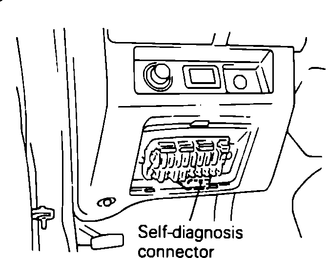
Self-Diagnosis Connector Location
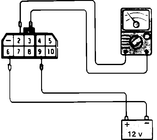
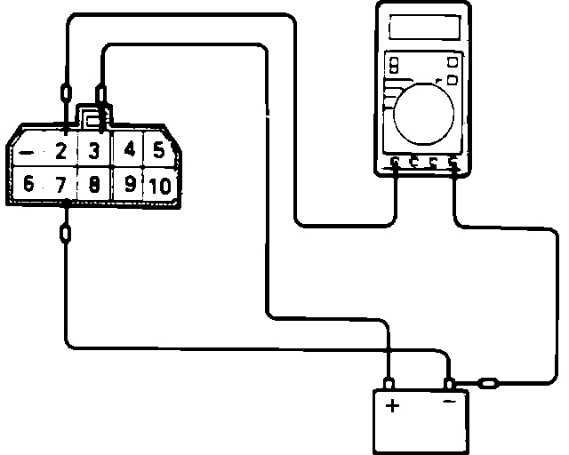
2. Does the ECU output a steady 12 vdc at the diagnostic check connector?
A. If not, and the ECU is suspected to be faulty, check the POWER AND GROUND CIRCUITS test to confirm that the ECU is being supplied with power and ground.
B. If so replacement of the ECU is required.
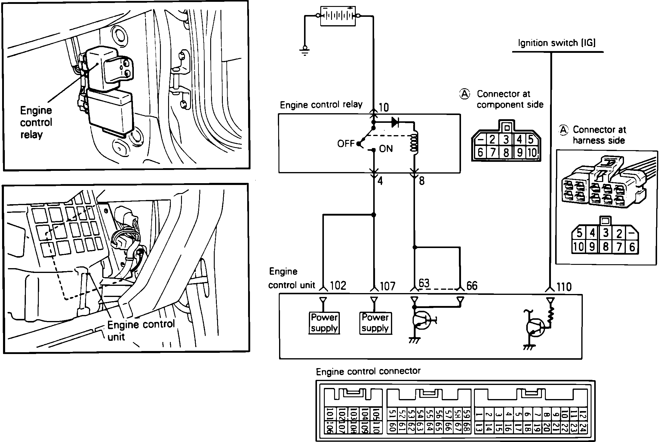
NOTE: Before replacing a ECU that is found to be faulty, insure that no other condition exists that will damage the new unit. This can be best done by testing the inputs and outputs to the ECU for over voltage/inappropriate power readings or grounds. Use the image in CHASSIS ELECTRICAL DIAGRAMS and the individual component testing procedures to identify the correct readings for each pin. Check all pins (at the harness with the ECU removed) that supply a signal to the ECU, for their correct readings and check all other pins to insure that there are no uncalled for voltage readings or grounds present.
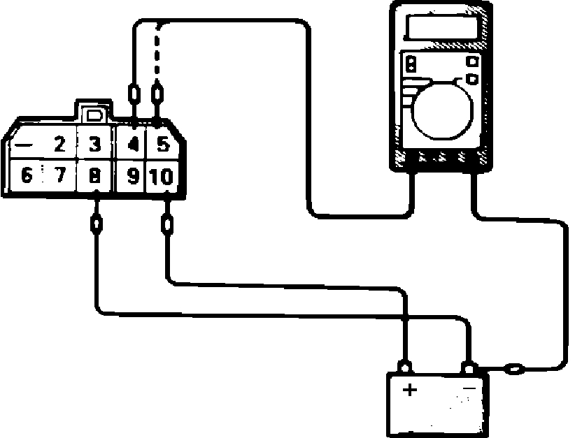
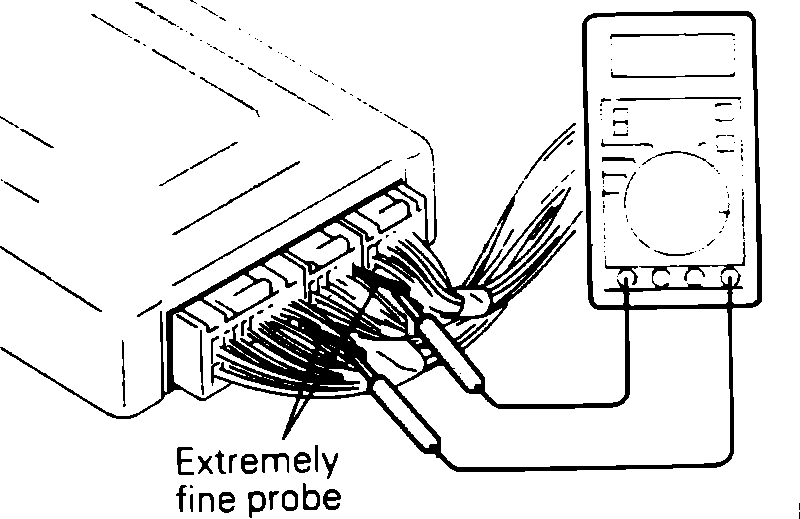
ECU Probing Technique
To test pins using a multi-meter do not remove the connector from the ECU, instead insert a straight pin or needle from the back side of the connector to access each pin.
NOTE: Before replacing an ECU that is found to be faulty, insure that no other condition exists that will damage the new unit. This can be best done by testing the inputs and outputs to the ECU for over voltage/inappropriate power readings or grounds. Use the ECU Terminal Identification image and the individual component testing procedures to Identify the correct readings for each pin. Check all pins (at the harness with the ECU removed) that supply a signal to the ECU, for their correct readings and check all other pins to insure that there are no uncalled for voltage readings or grounds present.
3. Compare all the remaining codes to the following list and perform the required inspections called for in each of the categories that are affected by a code.
Check power supply for:
1. Faulty battery.
2. Faulty fusible link.
3. Faulty fuse.
4. Check for faulty body ground.
Check fuel supply for:
1. Damaged fuel line.
2. Clogged or damaged fuel filter.
3. Faulty fuel pump.
Check ignition system for:
1. Faulty spark plugs.
2. Faulty ignition wiring.
3. Faulty distributor.
4. Faulty ignition coil.
Check emission control system for:
1. Faulty PCV system.
2. Faulty EGR system.
3. Vacuum leak.
4. Ignition timing and idle speed.
All categories:
ECU system faults are often caused by poor harness contact, therefore check that all of the connectors in all of the affected systems are secure and have continuity.
4. After completing all of the system inspections required in step 3 Perform all of the inspections and component tests (refer to COMPONENT TESTS) that are listed for each code that has appeared.
5. If faults were found in step 4, make repairs/replacements as required and clear the fault code from the ECU. Performance test the vehicle against the customer complaint and retest the ECU for fault codes.
6. If the same codes appear retest the repaired/replaced component, If it performs as specified, proceed to step 6.
7. If different fault codes appear, proceed to step 3, and attempt to resolve the new codes.
If NO fault codes were found in step 4, proceed to step 6.
8. If after performing all the required inspections though step 4, NO components were found to be faulty or at step 5 after repairs NO components were found to be faulty, replacement of the ECU is required.
After check and correction of malfunction is completed, disconnect battery ground cable or ECU connector for ten seconds or more to erase trouble codes. The memory is not erased if power supply is restored within ten seconds.
Let me know what you find.
Joe
Images (Click to make bigger)
Tuesday, January 1st, 2019 AT 5:07 PM