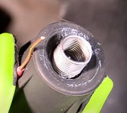
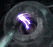
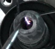
No Spark. Car cranks, but no spark from ignition coil.

Tiny
LEINADLTD
  • MEMBER
  • 1996 TOYOTA CAMRY
  • 2.2L
  • 4 CYL
  • FWD
  • AUTOMATIC
  • 216,540 MILES
A few days ago I took a corner from my house and the car just died. I got the car back to the house and the first thing I did was spray starting fluid down the TBI (Throttle Body Unit) to see if the car would start. The car did not start. That led me to suspecting something on the ignition side was wrong. I then removed the secondary coil wire going to the distributor cap and held it close to the strut tower to try and "see" a blue spark, as my dad was "cranking" the car. No luck. I then proceeded to check the resistance readings on the ignition coil and got 0.8 ohms on the primary side and 13.68k ohm on the secondary side. While there I check voltage from the end of the coil wire to ground, and also check the primary voltage to ground. Both read 12.41 volts. I then got my OBD-II tool and pulled codes P0401 and P0110. One code was the EGR valve and the other was the IAC (Intake Ambient Sensor). No other codes. I went on the safe side and removed the igniter and took it to AutoZone where it was tested several times using their Wells tester. All tests came back "PASSED". Thinking that something was not allowing the "coil" to collapse to induce a spark I check the CSS (Crankshaft Sensor). With the car cold it read 1348 ohms. I went to AutoZone and checked three of their CSS's and all read between 1340-1368 ohms. So, looking at a diagram from the Haynes manual I noticed that the Pick-up coil could possible cause this problem. So, I check the ohms on this and got 168 ohms. Doing some additional research some individuals have mentioned the IGf and IGt from the ECM. I do not know what else to check. I put new plugs, wires, distributor cap and rotor on a month ago. Is the coil bad? Why is there no spark with everything reading correct? Suggestions are welcomed.
Tuesday, August 25th, 2015 AT 5:05 PM

74 Replies

Tiny
SATURNTECH9
  • MECHANIC
  • 30,869 POSTS
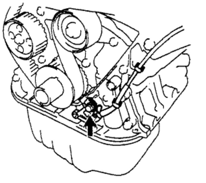
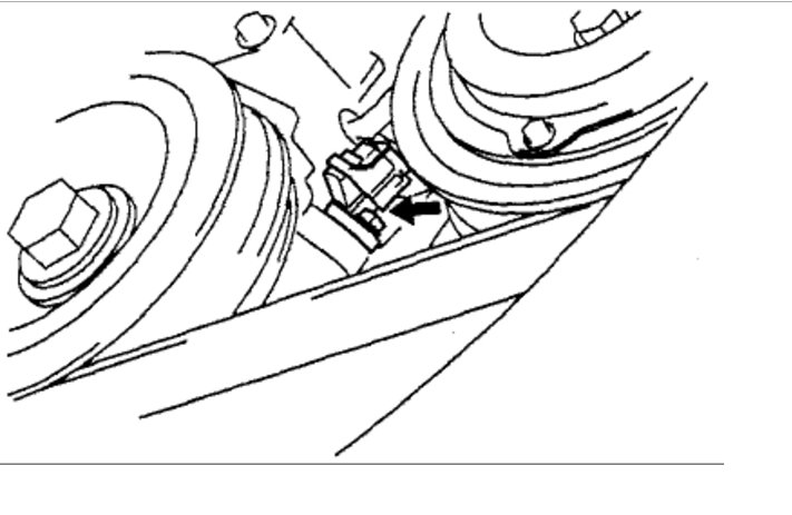
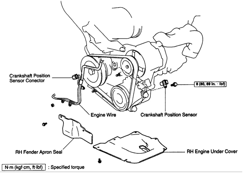
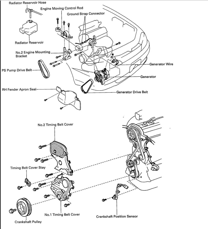
Testing a crankshaft sensor that way wont always work because everything changes when the sensor is in operation. It does sound like it is out though. Here is a guide that will show you what you are in for when changing it out with some diagrams (below) on how it will be like on your car.

https://www.2carpros.com/articles/crankshaft-angle-sensor-replacement

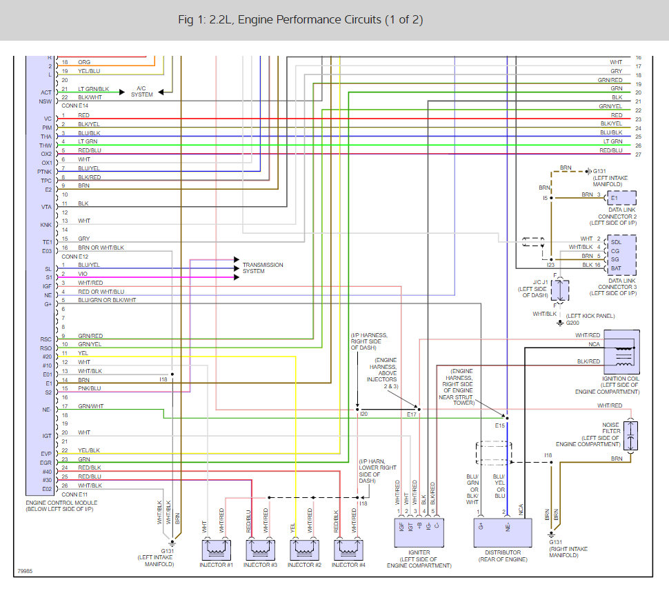
Next, with the key in the run position you should have battery power to the white wire with a red stripe at your coil.Also black wire with a red stripe should have a pulsing ground while cranking the engine?Check for the pulsing ground with a test light that will check your coil inputs to see if the coil is getting what it needs.

Here is a generic guide as well

https://www.2carpros.com/articles/car-cranks-but-wont-start

Please let us know what happens so it will help others.

Cheers
Was this
answer
helpful?
Yes
No
+4
Tuesday, August 25th, 2015 AT 7:23 PM
Tiny
LEINADLTD
  • MEMBER
  • 15 POSTS
Sorry it took so long to get back to you. I used a 12 volt test light and found that the light remain solid on both the white / red wire with the key "on", and while cranking the black with red stripe wire also remained solid. There was no Flicker or pulsating on the black / red wire. This might have been due to my LED test light. What does this mean? I only have two wires coming out of my distributor for my pickup coil. What is the next step? Ok just tested the same black / red wire using a 12 volt light bulb. The bulb did not pulsate, however it did dim when the car was cranking.
Was this
answer
helpful?
Yes
No
+3
Thursday, August 27th, 2015 AT 9:59 AM
Tiny
SATURNTECH9
  • MECHANIC
  • 30,869 POSTS
So there are two wire inputs into the coil?If so one is a constant power and the other is a pulsing ground while cranking that is what causes the coil to spark . also with the distributor cap off and cranking the engine the rotor on the distributor spins while the engine is cranking?

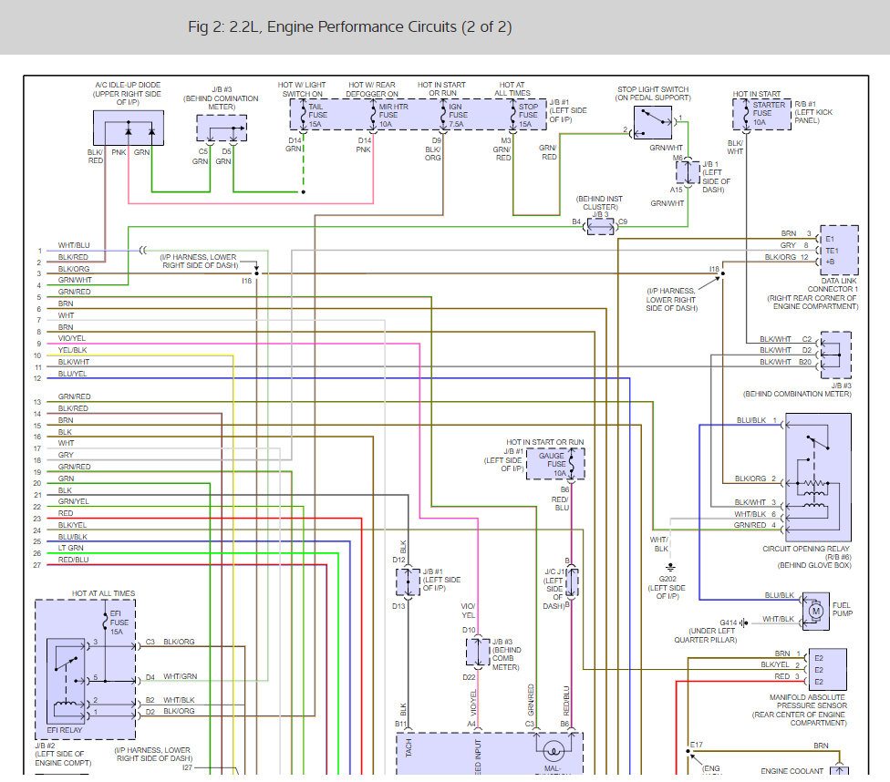
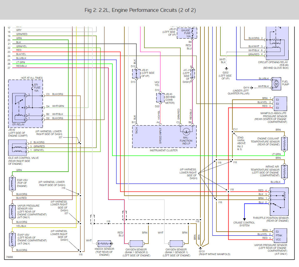
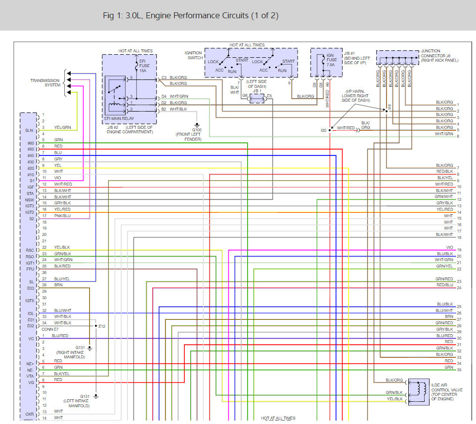
Here is a guide and some ignition system wiring diagrams to help with the testing.

https://www.2carpros.com/articles/how-to-check-wiring

I gave both 4 and 6 cylinders just in case.

Cheers,
Was this
answer
helpful?
Yes
No
+9
Thursday, August 27th, 2015 AT 12:20 PM
Tiny
LEINADLTD
  • MEMBER
  • 15 POSTS
Yes, the white / red wire has 12 volts on it. The black / red wire also has 12 volts and when you crank the car the test light does not pulse. We did this to make sure the timing belt was not broke. Its like the ignition coil is not collapsing to send the spark energy to the spark plugs. How can you check the pickup coil to see if the timing events are happening in order to make and break the ground on the ignition coil in order to induce a spark on the secondary side, so that spark energy is sent to the spark plugs? Remember, the igniter was tested at autozone on their wells tester and show to be good several times. What would you like me to check next?
Was this
answer
helpful?
Yes
No
+7
Thursday, August 27th, 2015 AT 3:02 PM
Tiny
SATURNTECH9
  • MECHANIC
  • 30,869 POSTS
It sure sounds like the crankshaft angle sensor is bad. I would try replacing it they go bad all of the time.

Here is a the Denso sensor on Amazon for $53.00

https://www.amazon.com/gp/product/B00PYQB40A/ref=as_li_qf_sp_asin_il_tl?ie=UTF8&tag=2carprcom-20&camp=1789&creative=9325&linkCode=as2&creativeASIN=B00PYQB40A&linkId=3bc24fda11629fb9ea31f9aa822f7a32

Here is some testing guides from the book:

Real Fixes
Component Tests
Common Replaced Parts
0k25k50k75k100k125k150k175k200k012
ignition control module...
distributor rotor (1)
ignition coil (1)
ignition distributor ca...
spark plug (1)
ENGINE DOES NOT START, REPLACED IGNITION CONTROL MODULE

Complaint
The customer states the engine will not start.

Cause
Confirmed the customer's complaint and found the engine did not start. Performed a visual inspection of the fuel system and ignition system components, but found no obvious faults. Removed the spark plugs and performed a visual inspection, but found no obvious faults. Connected an inline spark tester to the ignition coil secondary lead, started the engine, and found the spark was intermittent. Used a multi-meter to measure the resistance of the ignition coil and found the measured resistance was within specifications. Connected a lab scope to the ignition coil primary signal circuit, started the engine and found an erratic signal. Performed a visual inspection of the ignition control module wiring harness and connector terminals, but found no obvious faults. Key on, engine off, used the multi-meter to check for voltage and ground at the ignition control module and found both were present. Connected the lab scope to the ignition control module primary signal trigger input, started the engine and found the waveform revealed no faults with the primary trigger. This indicated the ignition control module was faulty.

Correction
Replaced the ignition control module and verified the vehicle operated properly. The customer's concern did not return.

Real Fixes

Fixed It!

Engine Does Not Start, Replaced Ignition Control Module
51?
The customer states the engine will not start. Confirmed the customer's complaint and found the...

Engine Does Not Start, Replaced Ignition Coil, Ignition Control Module
The customer states the engine will not start. Confirmed the customer's complaint and found the...

Engine Does Not Start, Replaced Fuel Pump, Fuel Pump Relay
The customer states the engine will not start. Confirmed the customer's complaint and found the...

Engine Does Not Start, Replaced Ignition Coil, Ignition Control Module
The customer states the engine will not start. Confirmed the customer's complaint and found the...

Component Tests

Ignition Tests -> Carbureted/Fuel Injection

Tests

Koec Test

KOEC test is best used for diagnosing no start, no spark condition.

Connect test leads at ignition coil:
Yellow=coil(-)
Black=known good ground.

KOEO, primary ignition voltage must be present to continue with test.

Crank Engine and check for ICM switching at ignition coil while cranking.

As ICM switches, primary voltage spikes can be seen.

Resistance Test

Secondary ignition wire resistance
Connect ohmmeter
Red=either end of plug wire
Blue=other end of plug wire

Read amount of resistance:

10k ohms per foot or

25k ohms total resistance per wire.

Ignition Tests -> Fuel Injection

Location

Type: conventional
Best test Location:
Distributor, coil, and igniter terminals.

Component Location:
Distributor: at rear of CYL head.
Coil and igniter: at left rear of Engine compartment near brake booster.

CYL #1 Location:

(front of vehicle) firing order 1-3-4-2distributor rotates counter-clockwise

Tests

Out Of Range No Sig Test

Connect test leads:
Yellow=coil(-)
Black=known good
Ground.
Key on, primary IGN
Voltage should be
Present.
Move test leads:
Yellow=coil(+)
Black=known good
Ground.
Key on, primary IGN
Voltage should be
Present.

Ignition Tests -> Fuel Injection/Carbureted

Operation

System is conventional ignition using one ignition coil to produce high voltage for all cylinders.

Primary windings create a magnetic field that when collapsed across secondary windings, create high voltage.

This high voltage is required to overcome the greatest KV requirement in the secondary (normally the spark plug gap) this high voltage is transmitted from the coil to the spark plugs through a coil wire, dist cap, rotor and spark plug wires.

Tests

Secondary Ignition Test

Component Test Meter can be used to view secondary ignition waveforms.

CH1=Yellow secondary coil adapter.
GND=Black secondary coil adapter lead.
Black clip=known good ground.

Note: See LAB scope plug-in manual for proper hook up information.

Sweep , scale and delay may need to be adjusted depending on engine RPM and firing voltage.

Current Ramp Test

Ignition coil current can be checked using Component Test Meter & a low amp current Probe.

Connect current Probe to Component Test Meter as shown.

Perform auto zero adjustment before any measurements. This adjustment should be done prior to clamping Probe around any wire.

Press the auto zero button to zero Probe.

Clamp current Probe around the b+ side or the Control side of ignition coil. Do not clamp around both.

If coil is difficult to access, it may be possible to check coil current at the fuse box, if applicable.

Verify that Probe jaws are fully closed. If a negative waveform appears,open jaws & clamp Probe in other direction.

Ignition coil waveform should have a gradual rise or ramp as current begins to flow.

If vehicle is DIS equipped, current flow through each coil should be about the same.

If not, suspect resistance in power supply or ground circuits,or possible aftermarket assy not matched with OEM units.

If coil waveform has a sharp rise at the begining of the ramp upward, suspect shorted coil windings.

i have sure track a data base you type code symptoms etc in and this is what came up i know the ignition control module tested good on there machine but thats what came up on sure track.

Please let us know
Was this
answer
helpful?
Yes
No
Thursday, August 27th, 2015 AT 9:44 PM
Tiny
LEINADLTD
  • MEMBER
  • 15 POSTS
Wow! That is a lot of information. I was reading through that and I do NOT have access to an oscilloscope to check for waveforms. What would be your suggestion? What can I check using a digital voltmeter and a test light to see why my coil is not collapsing to induce a spark? What component(s) cause the coil to collapse to induce a spark? How can I check those components? Thanks.

I purchased the Denso unit a genuine crankshaft sensor and I placed the new component on the car and cranked the car. We are in luck! The car still started! I went one step further and bought a new coil. You guy are the best! Thanks.
Was this
answer
helpful?
Yes
No
+3
Thursday, August 27th, 2015 AT 10:20 PM
Tiny
WRENCHTECH
  • MECHANIC
  • 20,758 POSTS
This is a different expert. I was going to continue the troubleshooting in case the sensor did not fix it.

The first thing we need to do is run a few more tests to get the entire picture and see if any other systems have issues.
This is a series of tests that is used on all crank, no starts to isolate what is going on. You may have already done some of it but complete the parts that you haven't yet and we'll go from there.

Side note: That P0110 is for an IAT (intake air temp) sensor circuit. That can cause the engine to go very rich s you should get that resolved.

All "crank, no start" conditions are approached in the same way. Every engine requires certain functions to be able to run. Some of these functions rely on specific components to work and some components are part of more than one function so it is important to see the whole picture to be able to conclude anything about what may have failed. Also, these functions can ONLY be tested during the failure. Any other time and they will simply test good because the problem isn't present at the moment.
If you approach this in any other way, you are merely guessing and that only serves to replace unnecessary parts and wastes money.

Every engine requires spark, fuel and compression to run. That's what we have to look for.

These are the basics that need to be tested and will give us the info required to isolate a cause.

1) Test for spark at the plug end of the wire using a spark tester. If none found, check for power supply on the + terminal of the coil with the key on.

2) Test for injector pulse using a small bulb called a noid light. If none found, check for power supply at one side of the injector with the key on.

3) Use a fuel pressure gauge to test for correct fuel pressure, also noticing if the pressure holds when key is shut off.

4) Do a complete compression test on all cylinders

Once you have determined which of these functions has dropped out,
you will know which system is having the problem.
Was this
answer
helpful?
Yes
No
+7
Thursday, September 3rd, 2015 AT 2:09 AM
Tiny
LEINADLTD
  • MEMBER
  • 15 POSTS
Okay, let's take it from the top. I will conduct the tests that you asked; however, it may take me 2-3 days to get your results. Monday is a holiday. I will talk to you Tuesday to see what we need to do and proceed from there. Thanks.
Was this
answer
helpful?
Yes
No
+3
Thursday, September 3rd, 2015 AT 4:20 PM
Tiny
LEINADLTD
  • MEMBER
  • 15 POSTS
Okay, I have conducted all the tests that you asked for. Here are the results:

Compression Test
Cylinder # 1: 190psi
Cylinder # 2: 180 psi
Cylinder # 3: 180 psi
Cylinder # 4: 190 psi

Fuel pressure reading at fuel rail: 40 psi; Yes, it does hold pressure for several minutes.

Spark Plug Spark Test:
Cylinder # 1: no spark
Cylinder # 2: no spark
Cylinder # 3: no spark
Cylinder # 4: no spark

Voltage was available on the + B side of the coil measured on the white / red wire. This reading read 12 volts on my digital voltmeter.

Finally, checking the fuel injectors using a noid light revealed No flashing with the noid light. However, 12 volts was present on one wire of each fuel injector when measured to ground using my digital voltmeter.

Now that these tests have been completed. What suggestions do you have that I might check on this vehicle? Thanks.
Was this
answer
helpful?
Yes
No
+6
Sunday, September 6th, 2015 AT 11:45 AM
Tiny
WRENCHTECH
  • MECHANIC
  • 20,758 POSTS
OK, what you have proven is that you are lacking pulse for both ignition and injector. That is determined by the reference signal supplied by the Crank sensor. That is where I would concentrate. It can be the sensor or any related wiring or even the ECM.

Here is a quick test for the sensor.

CRANKSHAFT POSITION SENSOR INSPECTION

NOTICE: "Cold" and "Hot" in the following sentences express the temperature of the sensor itself.
"Cold" is from -10°C (14°F) to 50 °C (122°F).
"Hot" is from 50°C (122°F) to 100°C (212 °F).

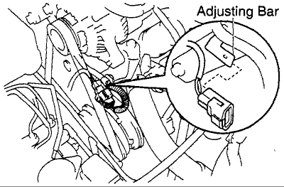
DISCONNECT CRANKSHAFT POSITION SENSOR CONNECTOR FROM GENERATOR DRIVE BELT ADJUSTING BAR
INSPECT CRANKSHAFT POSITION SENSOR RESISTANCE
https://www.2carpros.com/images/external/79036105.jpg.gif

Using an ohmmeter, measure the resistance between terminals.

Resistance:

Cold: 985 - 1,600 Ohms
Hot: 1,265 - 1,890 Ohms
If the resistance is not as specified, replace the crankshaft position sensor.

RECONNECT CRANKSHAFT POSITION SENSOR CONNECTOR
Was this
answer
helpful?
Yes
No
+2
Sunday, September 6th, 2015 AT 12:00 PM
Tiny
WRENCHTECH
  • MECHANIC
  • 20,758 POSTS
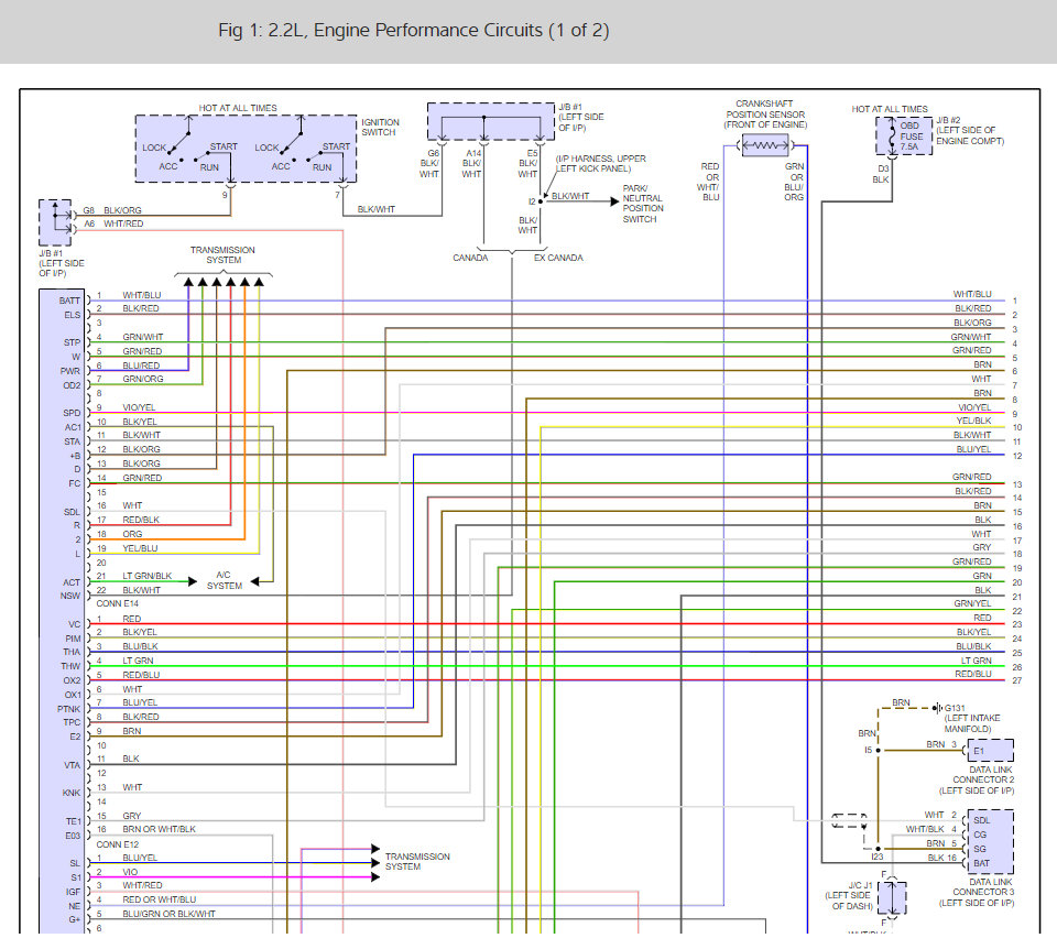
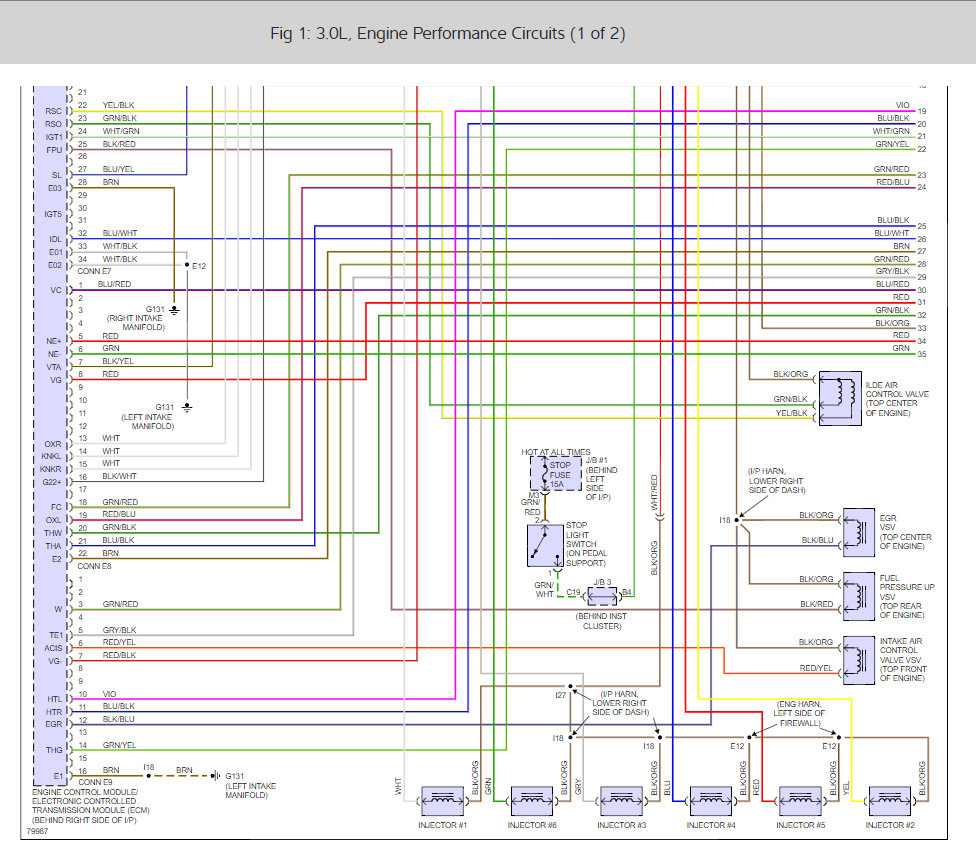
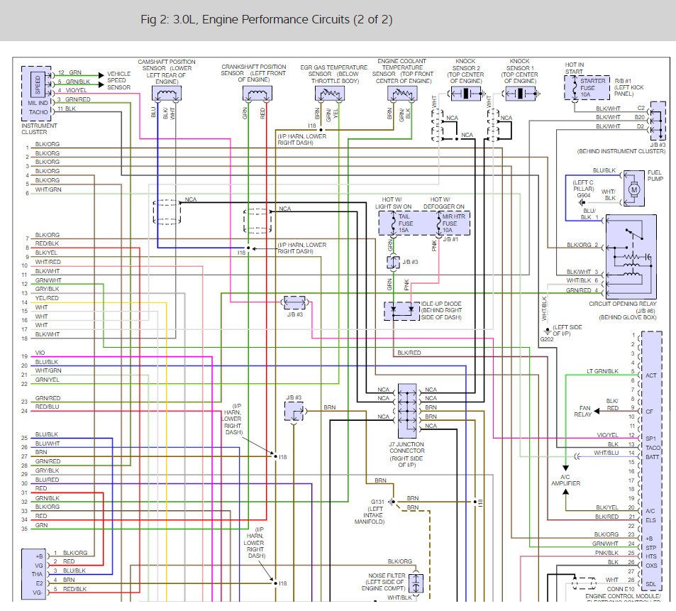
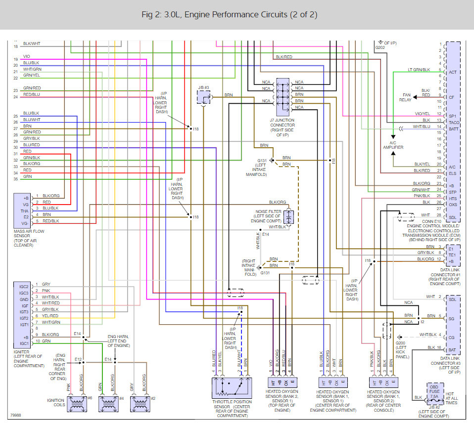
Check out the wiring diagrams in this post a few answers up
Was this
answer
helpful?
Yes
No
+4
Sunday, September 6th, 2015 AT 12:37 PM
Tiny
LEINADLTD
  • MEMBER
  • 15 POSTS
Thank you for the information. We checked the resistance on the crankshaft position sensor and got a value of 1450 ohms. The outside temperature was less than 100 degrees. I went one step further and check the continuity between the orange / blue wire on the crankshaft position sensor and the blue / yellow wire on the distributor. The wire ohmmed. I then proceeded to set my digital voltmeter on the 4 volt scale and as the car was cranking I observed a fluctuating voltage reading from 0.254 - 0.289 on the blue / yellow wire going into the distributor. I still have no Smart coming out of the secondary side on my mission coil. What should suggestion can I try or do you have?
Was this
answer
helpful?
Yes
No
+2
Tuesday, September 8th, 2015 AT 1:34 PM
Tiny
WRENCHTECH
  • MECHANIC
  • 20,758 POSTS
Use a scan tool and see if you have an RPM signal when cranking.
Was this
answer
helpful?
Yes
No
+2
Tuesday, September 8th, 2015 AT 2:04 PM
Tiny
LEINADLTD
  • MEMBER
  • 15 POSTS
Is this the same as an obd2 scanner
Was this
answer
helpful?
Yes
No
+2
Tuesday, September 8th, 2015 AT 2:09 PM
Tiny
WRENCHTECH
  • MECHANIC
  • 20,758 POSTS
Yes, anything that will give you an RPM reading.
Was this
answer
helpful?
Yes
No
+1
Tuesday, September 8th, 2015 AT 4:11 PM
Tiny
LEINADLTD
  • MEMBER
  • 15 POSTS
Using the obd2 tool I was able to use the freeze data function of the scanner to obtain an engine RPM value of 1269. What is the next step?
Was this
answer
helpful?
Yes
No
+2
Tuesday, September 8th, 2015 AT 9:19 PM
Tiny
WRENCHTECH
  • MECHANIC
  • 20,758 POSTS
Using freeze frame is not a good way to do that. You need a live reading you can watch while cranking to be sure. If you do confirm a tach signal, I think I would try another distributor.
Was this
answer
helpful?
Yes
No
-1
Wednesday, September 9th, 2015 AT 1:58 AM
Tiny
LEINADLTD
  • MEMBER
  • 15 POSTS
Thank you for the information. It may take me 2 to 3 days to obtain a scan tool that can detect "live" information as the car is cranking. I will keep you updated, thanks.
Was this
answer
helpful?
Yes
No
Wednesday, September 9th, 2015 AT 6:23 AM
Tiny
WRENCHTECH
  • MECHANIC
  • 20,758 POSTS
Even a lot of the cheap ones will do that.
Was this
answer
helpful?
Yes
No
+1
Wednesday, September 9th, 2015 AT 3:24 PM
Tiny
LEINADLTD
  • MEMBER
  • 15 POSTS
I consider myself a pretty smart guy, but for the life of me I do not know what function to use on the scan tool to find the RPM signal that you are asking get about. It is not the freeze frame data, and the only thing left is the MIL function on this OBD-II reader. I do have access to a newer scan tool that does freeze frame, MIL, live data, and ABS. Your guidance is appreciated.
Was this
answer
helpful?
Yes
No
+2
Thursday, September 10th, 2015 AT 11:34 AM

Please login or register to post a reply.

Sponsored links