No power from HVAC resistor?

Tiny
BADKITTY795
  • MEMBER
  • 2004 GMC ENVOY
  • 6 CYL
  • 2WD
  • AUTOMATIC
  • 170,000 MILES
My son's vehicle listed above has been problematic. When we first got it, I found someone had jumpered the power from the HVAC pigtail directly to the blower motor.

So far, I have wired in a new pigtail, replaced the module, resistor and blower motor pulled out all the actuators and when power is put to them, they all function.

When I check voltage coming from the pigtail, I have power. When I go through each of the fan speeds, I get battery voltage. When I plug in to the resistor, I have no power coming out of the resistor on the main wire that plugs in to the blower motor. I have exchanged the resistor 4 times from two different parts houses. I am stumped.

I'm not great at car electrical, so maybe I'm doing something wrong, but I've been chasing this problem for a year now and we still have no power to the blower motor.

Oh, and the rear blower does not function either.

Please help!
Tuesday, September 12th, 2023 AT 3:09 PM

25 Replies

Tiny
CARADIODOC
  • MECHANIC
  • 33,744 POSTS
I have a suspicion the confusion is due to taking voltage readings when things are unplugged. Equate that to stepping on a garden hose with your foot, so its 99 percent blocked. If you close the nozzle, you'll still have full pressure at the end of the hose, but open the nozzle and pressure after your foot will drop to almost nothing and very little water will flow. To be valid, for this type of problem, take all the readings when everything is plugged in and connected. That usually means back-probing through a connector alongside the wire.

This diagram shows the circuit for a manually controlled system. I added a couple of arrows pointing to connector terminals that can commonly cause what you described. Look for melted plastic and brown or black terminals. A bad connection at these places will cause low voltage after that point, but only when current is trying to flow, meaning everything is plugged in.

Let me know if this helps. If you're still stumped, take the voltage reading at connector C2, terminal "G", (brown arrow), with everything plugged in and turned on, and tell me what you find.
Was this
answer
helpful?
Yes
No
+1
Tuesday, September 12th, 2023 AT 6:21 PM
Tiny
BADKITTY795
  • MEMBER
  • 15 POSTS
I should have mentioned that I have back probed with everything connected. Power at pigtail. Nothing at blower motor.
Was this
answer
helpful?
Yes
No
Thursday, September 14th, 2023 AT 12:37 AM
Tiny
CARADIODOC
  • MECHANIC
  • 33,744 POSTS
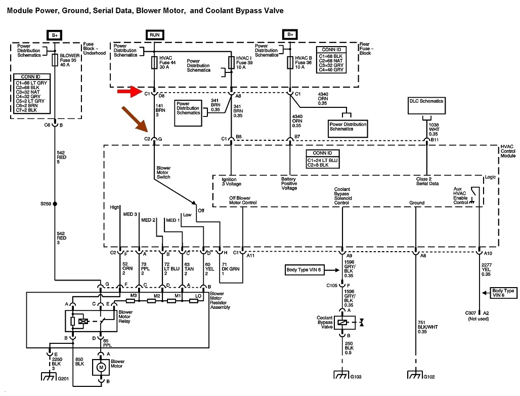
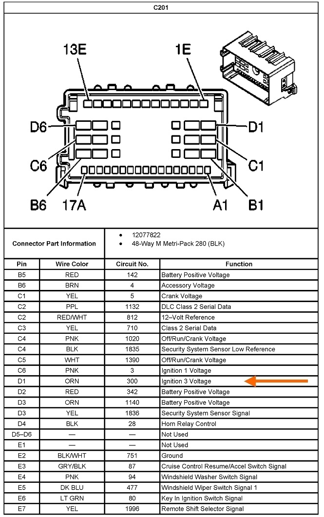
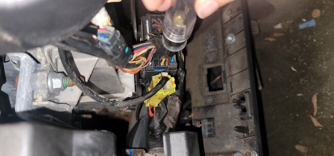
Dandy. What is the pigtail you're referring to? Can you point it out on the diagram? I chopped off the part of the diagram we don't need so I could enlarge the good part.

The following will help me understand what you've found so far:

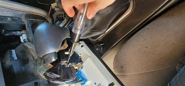
"When I check voltage coming from the pigtail, I have power."

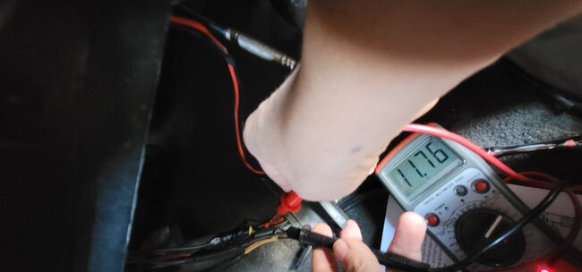
1. Where is that on the diagram, and what is the voltage you found? If you aren't sure how to follow diagrams, tell me the wire color, what it plugs into, the number of wires in total in that plug, or anything else that might help me find it on the diagram. Are you using a digital voltmeter or a test light? With this type of problem, a test light can be more accurate than a voltmeter, but either one will get this solved.

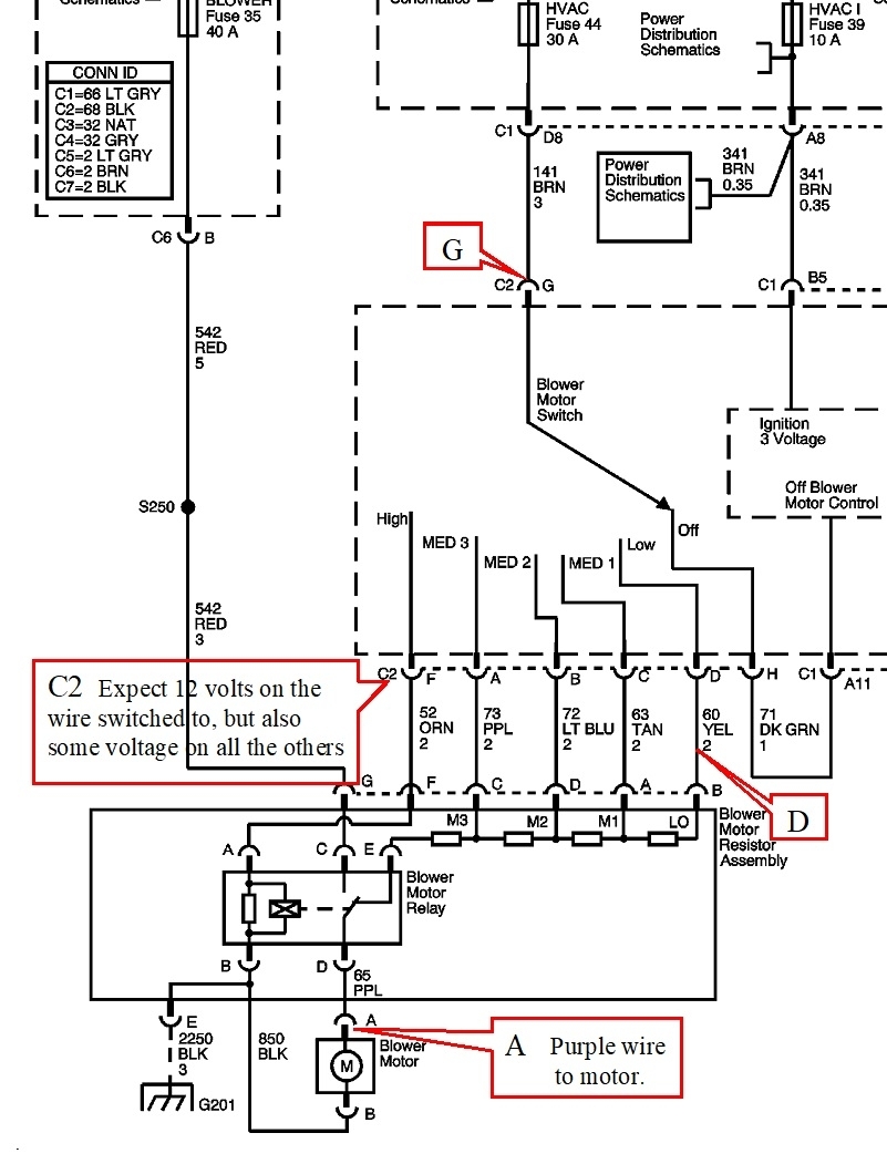
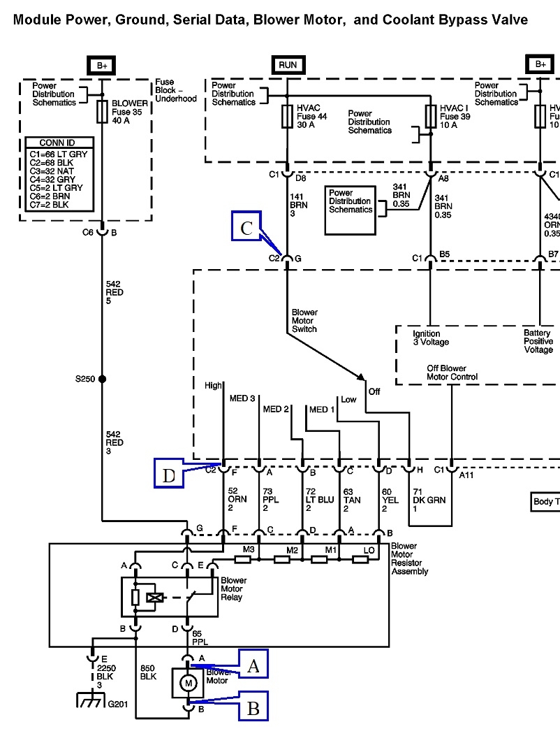
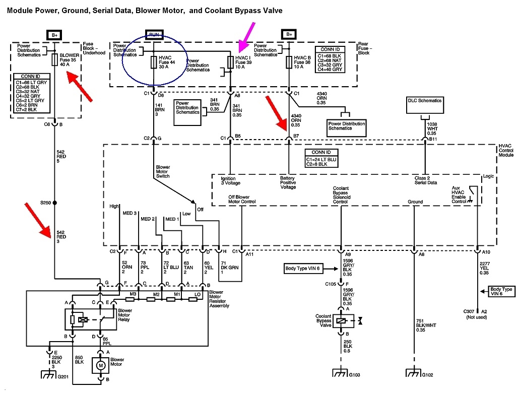
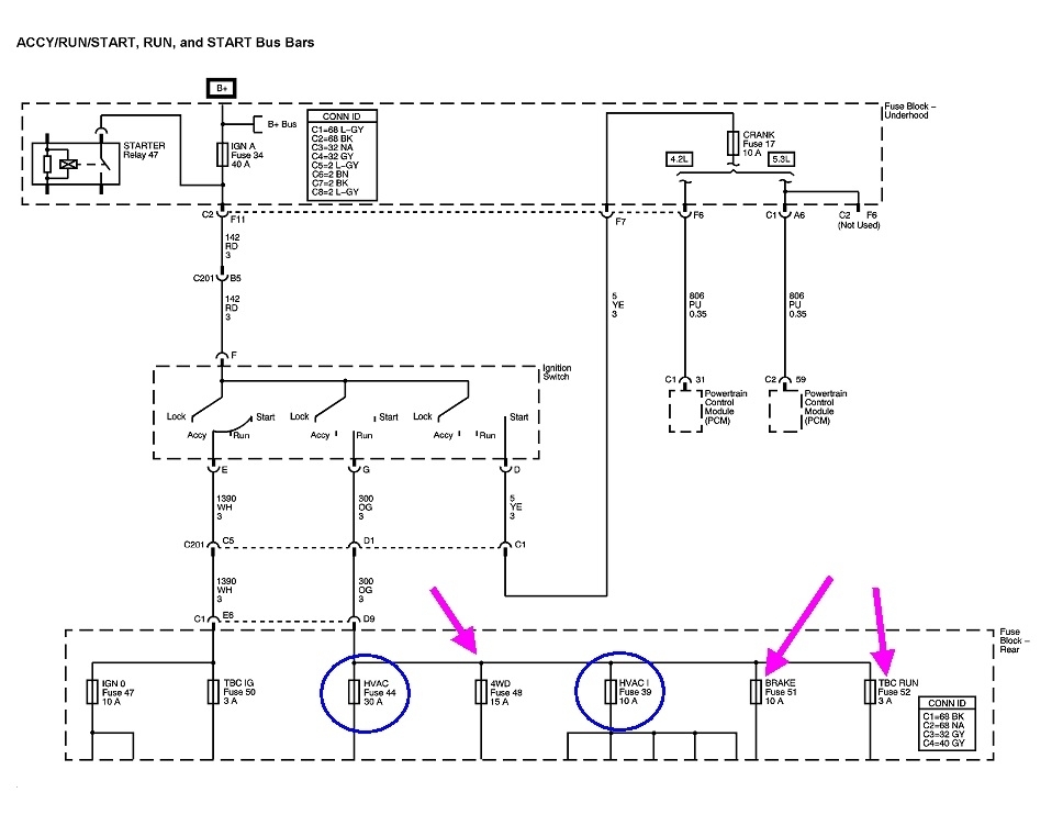
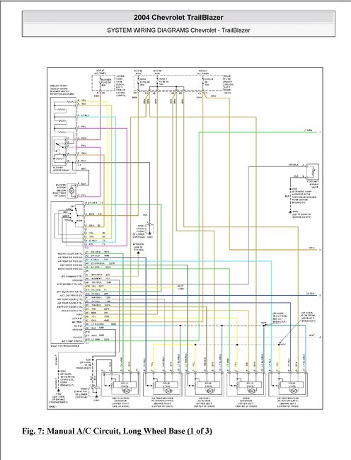
If you're measuring at point "A" on the purple wire at the motor, this is where my concern came from that you had everything plugged in. If you have 3 - 12 volts there in any speed setting, the motor will run unless there's a break in the ground circuit, (black wire). To identify that, measure on the motor's black wire. Don't worry if you find a couple of tenths of a volt. It's anything higher we don't want to see. That would be proof of a break in that circuit.

2. "When I go through each of the fan speeds, I get battery voltage".

Are you measuring at one point as you switch through the speed settings, or are you measuring at each of the wires in connector C2, terminals A, B, C, D, F, and H as you switch to the corresponding speed? There's a big potential source of confusion here. When you switch to a certain speed, you should find 12 volts on its corresponding wire, but at the same time, you will find some voltage on all the others. Suppose, for example, you switch to "Medium 2". There will be 12 volts on the light blue wire, terminal "B" at C2 on the controller, and on terminal "D" on the resistor assembly. Some of that voltage will go through the individual resistors in that assembly and appear at the resistor's other terminals. There is a way to check this further, but for this problem it's pointless. We don't care what exact voltages we find. If there's some, the motor should be running.

3. "When I plug in to the resistor, I have no power coming out of the resistor on the main wire that plugs in to the blower motor." This contradicts what you found in # 1 where you said you do have power. This is also why I assumed you had the purple wire unplugged from the motor and you were measuring on it. This is where my analogy of your foot on the garden hose comes from. A common cause of this problem is a badly overheated connector terminal somewhere in the circuit. That introduces a lot of resistance, just like standing on the garden hose introduces a lot of resistance to the flow of water. The voltage drop across the burned terminal, and the pressure drop across your foot, do not occur until you try to get current, or water, to flow THROUGH that resistance. That means having the hose connected to the faucet and the nozzle opened, and it means having the circuit connected to the fuse, and everything in that circuit connected so current has a path to flow.

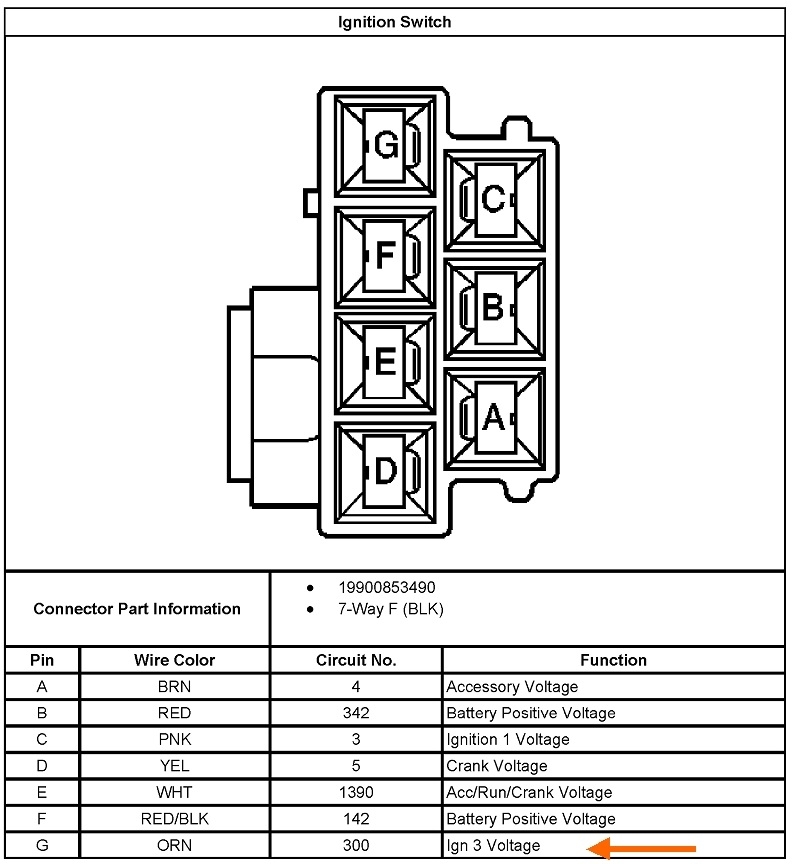
Use the red callouts I added to indicate where you found voltage, how much voltage, and if it depended on the speed switch position.

Part 2.

If I haven't confused you sufficiently yet, here's how I would approach this. Remember, unless specified, everything is plugged in and connected. When this is a circuit I'm just learning about, I start at the beginning, the battery positive post or the fuse for this circuit, then work my way through it, test point by test point, to the end, usually meaning ground. This involves the most steps and takes the longest since many of those test points are hard to find or hard to get to, but it will lead to you to the defect. Here we are most likely to find 12 volts at all the test points leading up to the defect, then, at the next test point right after the defect, we'll find 0 volts or very low voltage.

The more efficient way is to find a spot in the middle of the circuit and start there. You have to know what to expect, or what should be there for voltage. If you find voltage, everything has to be okay from the fuse, up to that point. The defect has to be in the second half of the circuit. You can do the same thing there. Find a convenient test point in the middle of that half, then decide if you have the voltage expected or not. This method requires the fewest steps and is the most efficient.

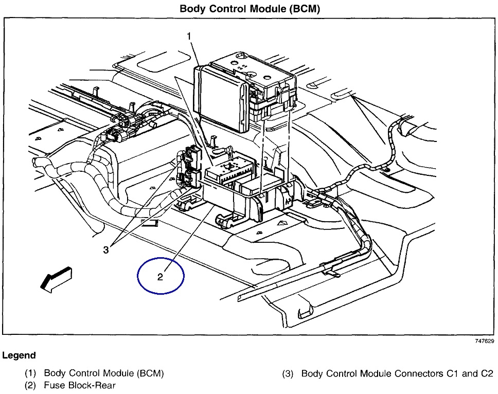
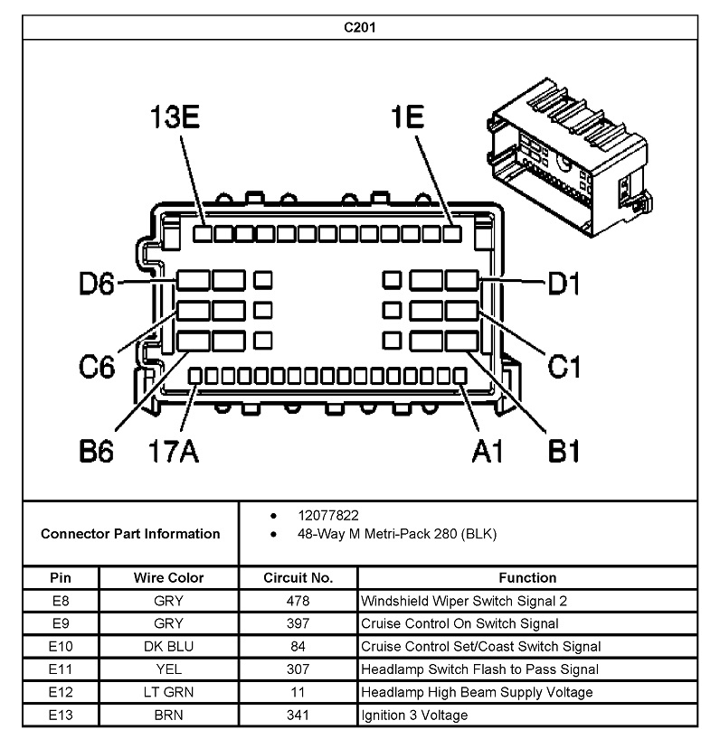
One clinker to my method is due to the most common cause of a dead fan motor being the motor itself, so I would start there. It's also usually an easy point to reach, right under the dash. Use the second diagram with the blue callouts. I'd measure at point "A". If there's voltage there, I'd measure at point "B" next. If there's voltage there, the ground circuit has a break in it. If's there's no voltage, the motor is defective.

Hint: If there's less than 12 volts at point "A", and close to 0 volts on point "B", the ground circuit, some of the original 12 volts is being dropped across the resistor assembly. That means current is flowing as it should, including through the motor. Electrically the motor is okay, but it has tight bearings. If unbolted and removed from the housing, you're likely to see it spinning very slowly. Tight bearings are an extremely common cause of resistor assemblies burning out repeatedly, as in every few weeks. Most of them in other car brands have a built-in thermal fuse.

To continue, if there's no voltage on the purple wire, I'd unplug it and measure again. If there's still 0 volts, I'm going to find a hard break, as in a disconnected plug, blown fuse, a switch turned off, or something like that. If there is 12 volts now, it points to excessive undesired resistance in the circuit. That's when I'd expect to find a blackened terminal, often with melted plastic around it.

Another hint: Digital voltmeters work by measuring electrical pressure, (voltage). As such, practically no current flows through them for it to do its job. When the defect is excessive resistance, all it takes is a tiny tickle of current to sneak through for the voltmeter to falsely "see" 12 volts. That's the same as finding 50 psi of water pressure at the closed nozzle on the hose while your foot is blocking that hose by 99 percent.

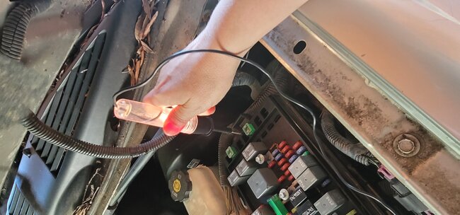
The common, old-fashioned test lights work by current flowing through them to make the incandescent bulb's filament glow. With a defect of excessive resistance in the circuit, not enough current can get through to light up that test light. That's why they can provide more accurate results. The test light is taking the place of the unplugged motor. The downside here is fan motors typically draw more than five amps, which might not be able to get through the defect. Test lights typically draw just a fraction of an amp. That MAY be able to get through.

Hint number three is if you care to experiment, use the test light AND the voltmeter at the same time. The test light will cause current to want to flow through the defect and will cause a corresponding drop in voltage. The voltmeter will show something significantly less than 12 volts while the test light's brightness is hard to differentiate between those small differences in voltage.

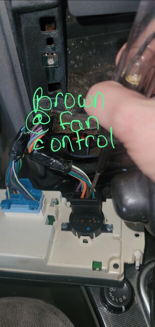
Next, if I didn't find a defect related to the motor, point "C" is the next place I'd look. I know the defect has to be somewhere near the controller, and it's going to have to be removed anyway, so I'll do it now to take this reading. If the 12 volts is missing, it can only be a blown fuse or a break in the brown wire. If I DO have 12 volts, point "D" is the last place to look. 12 volts there indicates the resistor has the defect in it. 0 volts means the defect is in the switch assembly.

To add one more note of value, since as far back as at least the early '70s, GM has used a relay to switch 12 volts directly to the motor for the highest speed. The relay's contacts can handle that high current better than all those connector terminals involved with the lower speeds. This provides a major clue. If the resistor is burned out, or its thermal fuse is burned out, the fan motor will still run on the highest speed. On older models, the relay is separate and the fan will run on "high" even when the resistor assembly is unplugged. On your model, they added a clinker to the story. That relay is built as part of the resistor assembly. The circuit still works the same way, but the resistor assembly must remain plugged in.

I think I covered every possible cause and how to find it with these voltage readings. If I have you too confused, just take as many of the readings as possible and tell me the places and the voltages you found, then we'll figure out where to go next.
Was this
answer
helpful?
Yes
No
+1
Thursday, September 14th, 2023 AT 5:02 PM
Tiny
BADKITTY795
  • MEMBER
  • 15 POSTS
This is a lot of info and I'm so appreciative. I have used a test light and a voltmeter, but now have some new things to try. I work nights but will go through some things in the morning when I get home and get pictures. Hopefully one of the suggestions you made will find the culprit, but, if not, I will post pictures and make notes on the diagram so that we can take it from there. Thank you!
Was this
answer
helpful?
Yes
No
Friday, September 15th, 2023 AT 12:38 AM
Tiny
KEN L
  • MASTER CERTIFIED MECHANIC
  • 42,924 POSTS
CARADIODOC is one of our best! Use 2CarPros anytime, we are here to help. Please tell a friend.
Was this
answer
helpful?
Yes
No
Monday, September 18th, 2023 AT 10:21 AM
Tiny
CARADIODOC
  • MECHANIC
  • 33,744 POSTS
Aw shucks. I have a lot of people fooled into thinking I'm a genius. Please let us know what you find or if we need to go further.
Was this
answer
helpful?
Yes
No
Monday, September 18th, 2023 AT 8:20 PM
Tiny
BADKITTY795
  • MEMBER
  • 15 POSTS
I've been trying to post my update since yesterday, but after 5 tries, it won't post. I'll keep trying, but basically, still no power to blower.
Was this
answer
helpful?
Yes
No
Wednesday, September 20th, 2023 AT 6:43 AM
Tiny
BADKITTY795
  • MEMBER
  • 15 POSTS
Sorry it took a few days. After working a 12-hour night shift, all I want is a whiskey neat and my bed, so decided to wait till my day off. So, first, I made a "tester" out of the old plug from the resistor and a drill battery and confirmed the blower motor works quite well. But, new wrinkle. Previously, as I worked through the fan speeds I had battery voltage at the corresponding wire, now I only have battery voltage at the red power wire marked "g" no matter whether things are plugged or unplugged. I checked resistance on ground and had.5 ohms. I still had no power to the blower motor (of course, since no voltage at any speed). I tested using volt meter and test light.

I admit, I'm getting a bit overwhelmed, but I'm also very stubborn and want to figure this out. I'm including pics of what I got pics of the first one is just of my blower motor tester because I was kind of proud of it.

I also included pics of the pigtail to which I was referring and pics of my tests. Excuse the quality. I needed three hands and only had two.

Could this be a bad actuator?
Was this
answer
helpful?
Yes
No
Wednesday, September 20th, 2023 AT 6:48 AM
Tiny
CARADIODOC
  • MECHANIC
  • 33,744 POSTS
Okay, we have a dandy start. Terminal "G", (red wire), is the feed for the high speed only. That gets switched onto the motor through a relay which gets turned on through the fan speed switch. That circuit is going to work once we get the other speeds working.

When you say you had voltage during previous tests, but not now, that suggests the previous tests were done with a voltmeter. If there's excessive resistance across a mating pair of terminals, as when they're badly burned, enough current can get through to make the meter falsely show voltage has made it to that point. It only takes a couple of microamps to do that. Not nearly enough current can get through to power a test light, so those give more accurate results. Keep using the test light for now.

Also, when voltages are taken with everything plugged in, in this case, the motor will try to draw current but it can't get through that bad connection. Most of the 12 volts is "dropped" across that bad connection leaving next to nothing at the motor. Now the voltmeter WILL give the correct result as long as everything remains plugged in and connected.

For the next test, look for the brown wire in the connector for the HVAC controller. Back-probe that terminal next to the wire and tell me what you find. If you find 0 volts, (dark test light), check fuse # 44. If you have 12 volts there, (bright test light), back-probe the orange wire, set the speed switch to the highest speed, and tell me what you find there.
Was this
answer
helpful?
Yes
No
Wednesday, September 20th, 2023 AT 12:26 PM
Tiny
BADKITTY795
  • MEMBER
  • 15 POSTS
All right, so I did as you instructed. The results, with pictures. Using test light only (your explanation as to why really helped) Everything plugged in and connected, key on and/or engine running.

1. No light at brown wire at back of HVAC module.

2. No light on #44 fuse (I could have sworn I've done this particular test at some point, and it did light up, but I've been chasing this for a long while so who knows. I may have only checked continuity). I also swapped the fuse for another 30 amp. This fuse now lit up, but the one from the other spot did not light up when placed in the #44 slot).

3. For grins and giggles, I back probed the orange wire on the plug behind the temp controls (pretty sure that's power because I have checked it before. I have the schematics stored in my phone, but knew you'd know for sure) and got a light.

Again, I can't thank you enough for your continued assistance. This is precisely the type of help I have been wanting in trouble shooting this issue. Louise the Frankenvoy says thank you, too. (Her name is because she's being put back together with parts from dead Trailblazers, Ascenders and Envoys)
Was this
answer
helpful?
Yes
No
Saturday, September 23rd, 2023 AT 6:17 AM
Tiny
CARADIODOC
  • MECHANIC
  • 33,744 POSTS
Dandy. So, if you have 12 volts on the orange wire, the relay in the resistor assembly should be clicking on. Go back to that resistor assembly and feel if there's a clicking when you switch between "high" and other speeds. If there's no clicking, it's either too light to feel or we overlooked something.

Next, check for voltage on the red wire on the resistor assembly. That should have 12 volts all the time, regardless of fan speed switch or ignition switch positions. If it's missing, check fuse # 35, a 40-amp in the under-hood fuse box.

I typed up this last reply but apparently forgot to post it. Please accept my apology for being so slow.
Was this
answer
helpful?
Yes
No
Sunday, September 24th, 2023 AT 8:59 PM
Tiny
BADKITTY795
  • MEMBER
  • 15 POSTS
Don't apologize! Your help is invaluable! Sorry it took me so long to reply. Life has been hectic. So, no clicking at relay. I'm going to summarize where I do have power and where I don't.

Have power at:

1. Red wire going into resistor.
2. Orange wire behind temperature control at HVAC module
3. #35 fuse under hood (took fuse out to test for power. Fuse was intact and not blown.

No power at:

1. Orange wire behind fan speed control on HVAC module.
2. #44 fuse spot.
3. At any fan speed going on to resistor.
4. At plug that plugs into blower motor.

I included pics of what I double checked today. I've already included pics in previous posts of other things mentioned here.
Was this
answer
helpful?
Yes
No
Thursday, September 28th, 2023 AT 7:31 AM
Tiny
CARADIODOC
  • MECHANIC
  • 33,744 POSTS
Yippee! Now we're making progress. Think of this in terms of two circuits that can turn on the fan. One is that red wire fed from fuse # 35. That circuit is only used for the highest speed. All the other speeds are turned on through, for lack of a better description, the "switch" circuit. GM has done it this way since at least the 1960s, but the clinker here is for the highest speed, which is still done with a relay, as always, is that relay is built into the resistor assembly. That's different. To say that a less-complicated way, the highest speed will work once we have the other speeds working. This is also why you didn't feel the relay in the resistor assembly click.

You found the missing 12 volts on fuse # 44. Gotta have that for the fan to run. I hope I don't jinx this, but are you checking in two different fuse boxes? Fuse # 35 is in the under-hood fuse box. Fuse # 44 is in the rear fuse box.

I was confused at first, but then realized there's two orange wires for the controller. Check this first diagram to be sure I have this right. You have 12 volts at the three places with red arrows. 12 volts is missing from fuse # 44 in the blue circle. If that is right, check for 12 volts on fuse # 39. In the third diagram, fuse # 44 has an orange arrow pointing to it. Fuse # 39 has a green arrow. Both are tied together, so if you have 12 volts on one, it should be on both.

What you find on fuse # 39 will tell us where to go next.
Was this
answer
helpful?
Yes
No
Thursday, September 28th, 2023 AT 9:10 PM
Tiny
BADKITTY795
  • MEMBER
  • 15 POSTS
It may not have been clear in my previous pictures I've posted, but yes, I checked #35 under the hood and #44 under the rear seat.

Your red arrow on the schematics seem to confirm the places I have found power.

And for the really exciting bit, I checked #39 under the rear seat this morning and got no power! Never been so excited to see no result. I visually inspected the fuse and then also swapped it into another spot to make sure the fuse was good. (It is), but I've got no power at spot #39 with the ignition switched on.
Was this
answer
helpful?
Yes
No
Friday, September 29th, 2023 AT 5:21 AM
Tiny
CARADIODOC
  • MECHANIC
  • 33,744 POSTS
Wonderful. There's three more fuses tied to those two that are dead. This diagram is part of the Power Distribution system. The pink arrows are pointing to fuse # 48 for the 4WD. Fuse # 51 is for something related to the brakes, and fuse # 52 says, "TBC". Don't know if that's referring to the throttle body or something else.

Check for 12 volts on those three fuses. If at least any one of them has 12 volts, there has to be a break inside the fuse box. There's usually stainless steel buss bars in there with fuse socket terminals riveted to them. Those rivets are good places to find bad connections.

If all five of those fuses have 0 volts, we have to work back on the "OG" wire to the ignition switch. I don't know if "OG" means orange, orange with a green stripe, or something else. There's three connectors in that wire. Those are all good places to find burned terminals. One connector is plugged into the fuse box. One is on the ignition switch, and connector C201 is somewhere in between. A lot of GM models have wire harnesses running under the driver's foot area carpet. That's a common place to find corroded terminals.

Now that I checked, C201 is shown as up by the ignition switch, but that shouldn't be at the switch itself. According to the diagram, there's a different connector at the ignition switch.

The last three images are the connector view for C201. Here, in the second one, they DO show it as an orange wire. If you look at fuse # 44 with the blue circle in the first diagram, and follow that wire up, when it comes to C201, they show it's terminal # D1. I pointed that one out with the orange arrow. Hopefully somewhere along this wire you'll find a burned or corroded terminal. See if you have 12 volts anywhere along it. If not, the ignition switch becomes the best suspect.
Was this
answer
helpful?
Yes
No
Friday, September 29th, 2023 AT 9:26 PM
Tiny
BADKITTY795
  • MEMBER
  • 15 POSTS
I hope you're online because the pull it place closes in 2 hours. There was no power to any of the five fuses you had me test. I did find what looked like damage on the BCM ribbon cable on the side of the fuse box with the dead fuses. Could this be the issue? I haven't found any burned connections yet, but I haven't checked all of them yet. I'm posting a picture.
Was this
answer
helpful?
Yes
No
Sunday, October 1st, 2023 AT 1:05 PM
Tiny
BADKITTY795
  • MEMBER
  • 15 POSTS
I took the cable out of the car. (That was unnecessarily complicated). Then got it out of its housing. Pics are of the "A" side A4, 14, 16 and 17 are what look suspect. The part that plugs into the BCM also has some shmutz. I cleaned it a bit with alcohol but couldn't get it all off. I'm going to pull it yard tomorrow to get another because it definitely looks iffy, but I'm wondering if this is what could be the problem.

(Ignore the first 3 pics. I posted the wrong ones and have been trying to delete them, but the website is not cooperating.)
Was this
answer
helpful?
Yes
No
Sunday, October 1st, 2023 AT 3:00 PM
Tiny
CARADIODOC
  • MECHANIC
  • 33,744 POSTS
Ribbon cables like that often appear to "fix themselves" after being unplugged and reconnected. That's from the scratching action creating new shiny areas of contact. In this case, I find it hard to believe an engineer would use that cable for ignition switch current. Any one of those copper traces rolled up into a round wire would be way too small to handle the needed current. I wouldn't expect one or two amps to flow through there, and heater fan motors can draw up to ten amps. A ribbon cable connection wouldn't last very long.

I think what you found is a cable that connects multiple layers inside the fuse box.

Were you able to find connector C201? If you didn't yet, start there and see if you have 12 volts with the ignition switch in the "run" position. That's terminal "D1" in the drawing in my last reply, with the orange arrow. You'll notice that is one of the larger terminals in that connector, to handle the high current.

If you can't get to that connector easily, look for the connector on the ignition switch instead. The orange wire is terminal "G", at the top of the row of four terminals. If you don't have 12 volts there, that connector terminal is burned or there's a burned contact inside the switch.
Was this
answer
helpful?
Yes
No
Sunday, October 1st, 2023 AT 5:21 PM
Tiny
BADKITTY795
  • MEMBER
  • 15 POSTS
Thanks. I did get to c201, but then got distracted by the ribbon cable. On one pinout I found, it did say a couple of those spots were ignition, but who knows what they do. I will check the c201 terminal when I get home (went out to eat with the fam).
Was this
answer
helpful?
Yes
No
Sunday, October 1st, 2023 AT 5:34 PM
Tiny
BADKITTY795
  • MEMBER
  • 15 POSTS
No voltage at D1. I'm pretty sure I was on the right spot, so I'll have to do some more investigating tomorrow.
Was this
answer
helpful?
Yes
No
Sunday, October 1st, 2023 AT 7:02 PM

Please login or register to post a reply.

Sponsored links