No crank no start?

Tiny
JAVIERMLNDZ
  • MEMBER
  • 2007 CHEVROLET SILVERADO
  • 5.3L
  • V8
  • 4WD
  • AUTOMATIC
  • 121,000 MILES
I have the truck listed above that was running fine until I tried starting one morning to go to work but it did not crank. I checked the battery, and it was good, I still got power to the dashboard. I attached pictures of the codes I pulled to see if anyone can point me in the right direction.
Wednesday, August 9th, 2023 AT 2:26 PM

87 Replies

Tiny
AL514
  • MECHANIC
  • 4,110 POSTS
Hello, are you able to access the Body control module with your scan tool? It looks like it's offline from the vehicles network. With all those Lost comms to BCM, it looks like your scan tool pulled codes from 5 modules, I'll post a diagram of the High-Speed data bus, from the codes it looks like about half of that network is possibly down.
The Body Control module (BCM) is the gateway module for the different networks in the vehicle, the High speed to the lower speed network, so if the BCM is down, that is why you are missing so many other modules with a full system scan.
Here is the location of the BCM, check the connectors for any corrosion or any wiring issues. Go through the fuses as well to see if there are any that are blown. Since there are such a limited number of modules you're detecting, I don't think the BCM is either not powering up or its not receiving a wake-up signal from the ECM.

https://www.2carpros.com/articles/how-to-check-a-car-fuse

https://www.2carpros.com/articles/how-to-use-a-test-light-circuit-tester
Was this
answer
helpful?
Yes
No
Thursday, August 10th, 2023 AT 12:52 PM
Tiny
JAVIERMLNDZ
  • MEMBER
  • 51 POSTS
I'm not sure, I have the BlueDriver obd2 Bluetooth scanner, I'll be home in a few minutes.
Was this
answer
helpful?
Yes
No
Thursday, August 10th, 2023 AT 1:08 PM
Tiny
AL514
  • MECHANIC
  • 4,110 POSTS
Refresh this page, I posted some more information in my last post.
If you pull out the Run/Crank Relay and turn the key On, there should be battery power on 2 of the pins where the relay sits, Power for the H labelled circuit to the relay comes from the Ignition Switch, through the BCM to the Run/Crank Relay. If one of the power feeds is missing, we'll know where to start checking. Power for the Ignition switch comes from the DLIS Fuse 36 in the engine compartment Fuse Block. These BCMs can fail for a number of reasons, since they control so many circuits, a short can take them down pretty easy.
Was this
answer
helpful?
Yes
No
Thursday, August 10th, 2023 AT 1:10 PM
Tiny
JAVIERMLNDZ
  • MEMBER
  • 51 POSTS
The only blown fuse I found was the 20-amp Aux PWR on the inside fuse box, I am going to try disconnecting the battery and connecting the positive and negative terminals to drain the vehicle to see if it resets everything.
Was this
answer
helpful?
Yes
No
Thursday, August 10th, 2023 AT 1:29 PM
Tiny
AL514
  • MECHANIC
  • 4,110 POSTS
I posted some additional info, refresh the page again.
Was this
answer
helpful?
Yes
No
Thursday, August 10th, 2023 AT 1:32 PM
Tiny
JAVIERMLNDZ
  • MEMBER
  • 51 POSTS
Disconnecting the battery didn't do anything. I did what you said and disconnected the Run/Crank relay and pins 30 and 86 gad power with key on pin 85 is grounded. I added a picture of my dashboard, there is no communication with the fuel system, and you can't see in what gear I'm in.
Was this
answer
helpful?
Yes
No
Thursday, August 10th, 2023 AT 1:53 PM
Tiny
AL514
  • MECHANIC
  • 4,110 POSTS
Okay, this Aux fuse that you found blown is also in the same junction block left I/P, lower left side of the dash as the High Speed GMLAM Serial Data bus runs through. So, I would check for possible water intrusion or corrosion in that junction block. Thats the lower driver side dash.
Was this
answer
helpful?
Yes
No
Thursday, August 10th, 2023 AT 3:20 PM
Tiny
JAVIERMLNDZ
  • MEMBER
  • 51 POSTS
Is this it? I don't see anything wrong.
Was this
answer
helpful?
Yes
No
Thursday, August 10th, 2023 AT 3:47 PM
Tiny
AL514
  • MECHANIC
  • 4,110 POSTS
That's the front side of the Junction Block, the X2 and X3 connectors that have the High Speed GMLAN data wires. The ones running to the BCM. The 1st diagram is the front view of it, the 2nd diagram is the back side of the Junction Block.
The X2 and X3 connectors have the BCM network wires running through them.
The 8th diagram is all the modules and the entire network in the vehicle. The BCM is in the top right corner, its lost comms to the number of modules, and it's also the module preventing the truck from starting, so there is either a communication issue to and from the BCM or it is having some other wiring issue. As for this large junction Block, I'm not sure if it runs through the firewall or if you can get to the back side connectors to check X2 and X3.
The BCM is also located up under the driver side dash area (diagram 10).
On your code scan you can see that it's not even in the list of modules, so it's not communicating at all, and might not be powered up. Last one I had like this was a single trace burned on the BCM circuit board, causing all kinds of issues. GM runs more things through the BCM than any other module.
Was this
answer
helpful?
Yes
No
Thursday, August 10th, 2023 AT 4:16 PM
Tiny
JAVIERMLNDZ
  • MEMBER
  • 51 POSTS
This is all I'm able to see on the back side, don't have that much movement. From what I can see the wires look okay.
Was this
answer
helpful?
Yes
No
Thursday, August 10th, 2023 AT 5:02 PM
Tiny
AL514
  • MECHANIC
  • 4,110 POSTS
I know it looks like a tight fit back there, but that's where the BCM data wires branch out.
Diagrams 1-5. If you want to check the BCM comms on the Low-Speed network, there is a Splice Pack(comb) diagram 6, 7, 8 that you can check for a voltage signal from the BCM on pin M. These GM splice combs make it easy to check if a certain module is pulling down the Low speed network, If the BCM is not powering up at all, there will be a signal missing on the M pin, you can actually pull the comb out that connects all the modules together at that splice, and check that single wire from the BCM for a voltage signal.
The first diagrams are going to be more difficult to get a reading on the high-speed network. Just one other thing, if you plan to unplug the BCM to check the connectors for corrosion or anything like that, there is a TSB that states to disconnect the battery negative cable before disconnecting any of the BCM connectors or the module can be damaged. That blown fuse though is something that might point to the issue. Does that circuit still short to ground if you replace the fuse? If so, there is a wire touching ground and there might be more issues in that area.
Was this
answer
helpful?
Yes
No
Thursday, August 10th, 2023 AT 5:59 PM
Tiny
JAVIERMLNDZ
  • MEMBER
  • 51 POSTS
I replaced the fuse and it hasn't blown yet.
Was this
answer
helpful?
Yes
No
Thursday, August 10th, 2023 AT 6:13 PM
Tiny
JAVIERMLNDZ
  • MEMBER
  • 51 POSTS
Is that the splice you are talking about?
Was this
answer
helpful?
Yes
No
Thursday, August 10th, 2023 AT 6:46 PM
Tiny
JAVIERMLNDZ
  • MEMBER
  • 51 POSTS
I was able to find the jx221 splice and removed the comb to check pin m and it did not have voltage.
Was this
answer
helpful?
Yes
No
Thursday, August 10th, 2023 AT 8:35 PM
Tiny
AL514
  • MECHANIC
  • 4,110 POSTS
Yes, that looks like the splice comb for the low-speed network. The BCM communicates at both High speed and low speed and transmits messages across the two as a gateway. So, if you had no voltage with the key On, did you have voltage on any other pins? If possible, de-pin the M pin for the BCM and see if you have any voltage on that network without the BCM involved. It sounds like the BCM is not even powering up. Can you access it? It's got a 7-connector setup, this one looks to be pretty far up in the dash on the driver side, they are not usually in such a bad location, but if you can unbolt it without unplugging it and get it down where we can check its powers and grounds. That will be our next step. Did you try cranking as well and see if it blows that fuse again, I'm just concerned because it happens to run through that same connector X2 and then X4.

The good thing about those network combs (splices) is that we can pull modules off the network one by one there when diagnosing a problem. And the BCM is not setting any codes, that's a worry too.
Also, in the location circled in green, that first pin on the X2 connector, is there a Red/White wire coming out of that location. It doesn't look Red with a White stripe to me, but zooming in on the pic it gets pretty blurry, I'm wondering if these diagrams are incorrect in some places. Unfortunately, that is common.

I've come across many electrical TSBs for this model. There are all kinds of wiring issues under the dash
Diagrams 3-13 are TSB 1 with harness problem areas to check.
14.15 are TSB 2
16, 17, 18 are TSB 3.
And there are many more electrical TSBs, but they have to do with more wiper function and having to re-crimp connections that are faulty from the factory.
But these ones are about a very in-depth checking of the fuse panel in the engine compartment. For fuse/relay connections. So, a lack of power to the BCM from one of these more main power supplies is possible here too, there are many problem areas here. Since the BCM seems to be the first concern here, checking for power and ground, and then also any communication voltages right at the BCM connectors will let us know what its missing.
Was this
answer
helpful?
Yes
No
Friday, August 11th, 2023 AT 9:21 AM
Tiny
JAVIERMLNDZ
  • MEMBER
  • 51 POSTS
I believe this is the jx221 splice comb you mentioned at first and no I did not have any voltage or at any of the other pins with the key in the on position. I also cranked it a few times, but I do not recall checking to see if I had any blown fuses after that. I am currently out of town with the family de-stressing lol! I won't be back till Monday afternoon, hopefully I can take another look at it then. And no, I did not de-pin the M in this splice and check for voltage if this is the splice you are talking about.
Was this
answer
helpful?
Yes
No
Saturday, August 12th, 2023 AT 4:54 AM
Tiny
JAVIERMLNDZ
  • MEMBER
  • 51 POSTS
Here is another picture, the first pin in the x2 connector looks to be brown.
Was this
answer
helpful?
Yes
No
Saturday, August 12th, 2023 AT 5:06 AM
Tiny
JAVIERMLNDZ
  • MEMBER
  • 51 POSTS
And what 7 connector setup are you talking about here. The jx221 splice that I circled earlier in other picture with all green wires?
Was this
answer
helpful?
Yes
No
Saturday, August 12th, 2023 AT 5:17 AM
Tiny
AL514
  • MECHANIC
  • 4,110 POSTS
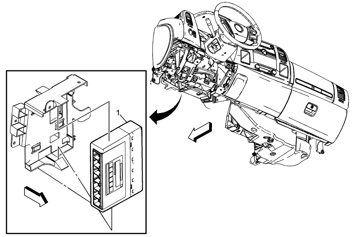
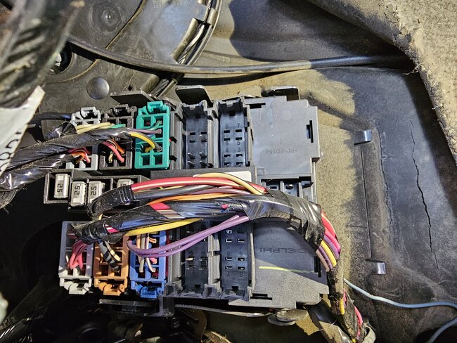
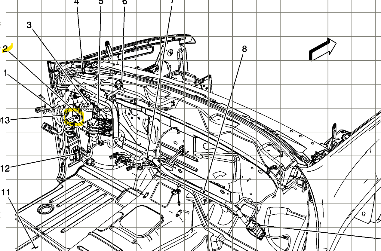
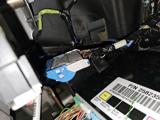
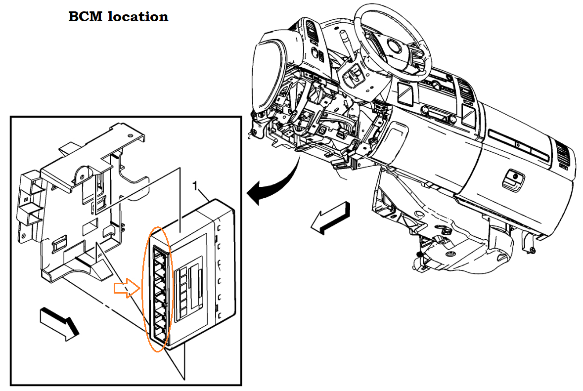
The Body Control Module has 7 connectors on it. This is how you can identify it easier.
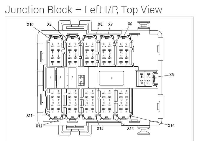
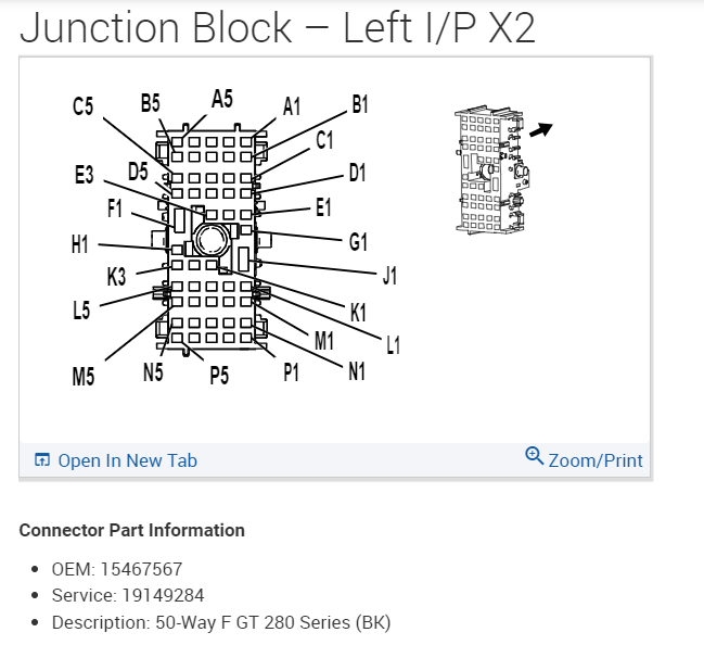
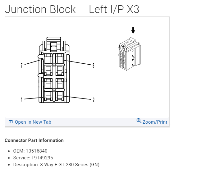
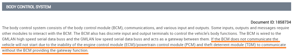
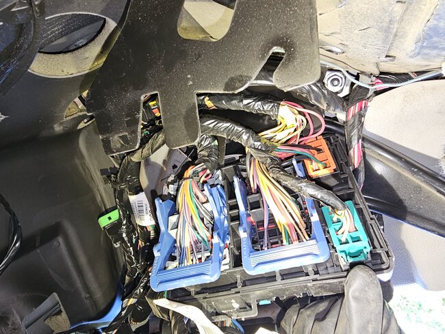
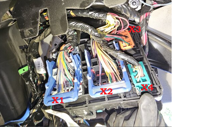
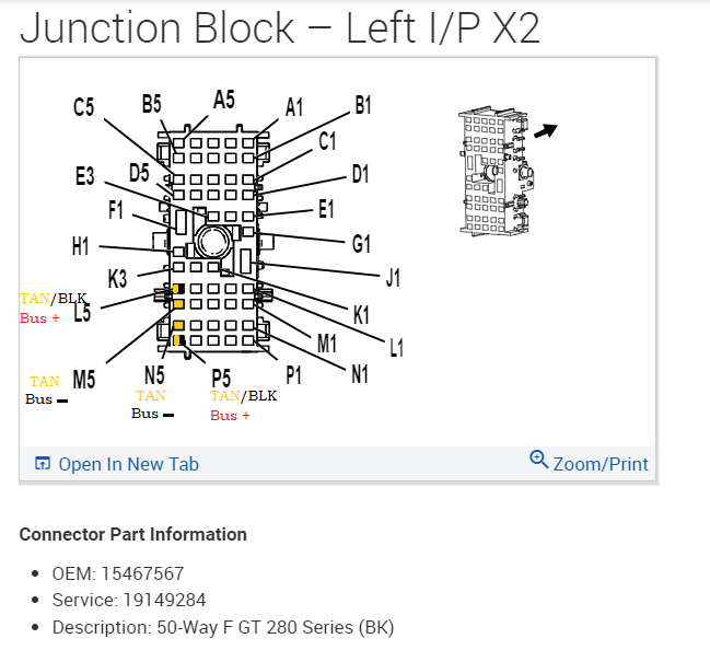
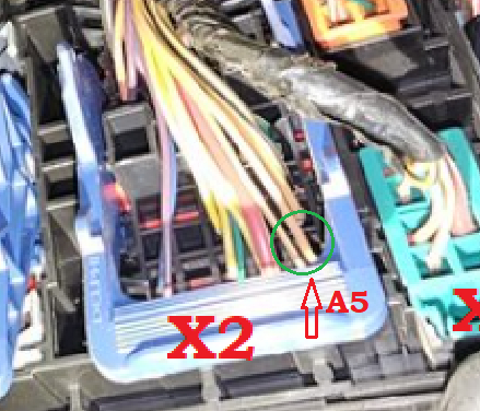
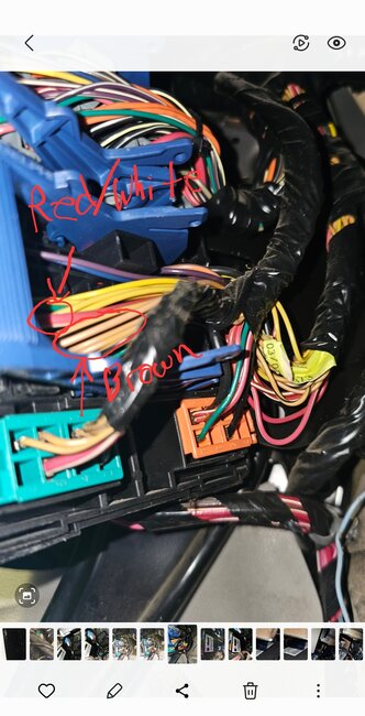
Yeah, I was looking at that X2 connector as well, Service info is not always correct so we have to do the best we can with what we have. In your 3rd post up, that module with all the colored connectors almost looks like the BCM, except I count only 6 connectors, I think. I'll double check that. I have seen so many BCM failures on these GM setups, any shorts seem to just disable the entire thing. But usually what happens is all the other modules with use the last known good data from the BCM to keep the vehicle running, which is why I think there is an issue with the High-speed network, The High-speed modules are the more important modules such as the ECM, TCM, ABS, etc. Things that have to do with safety, And the low speed is for lower priority components. But I want to help you get this thing back up and running.

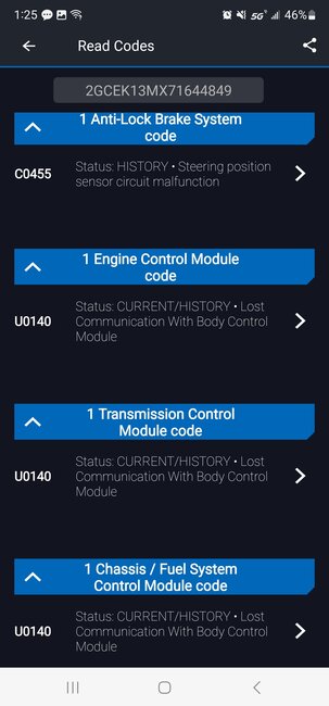
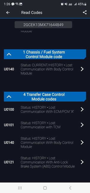
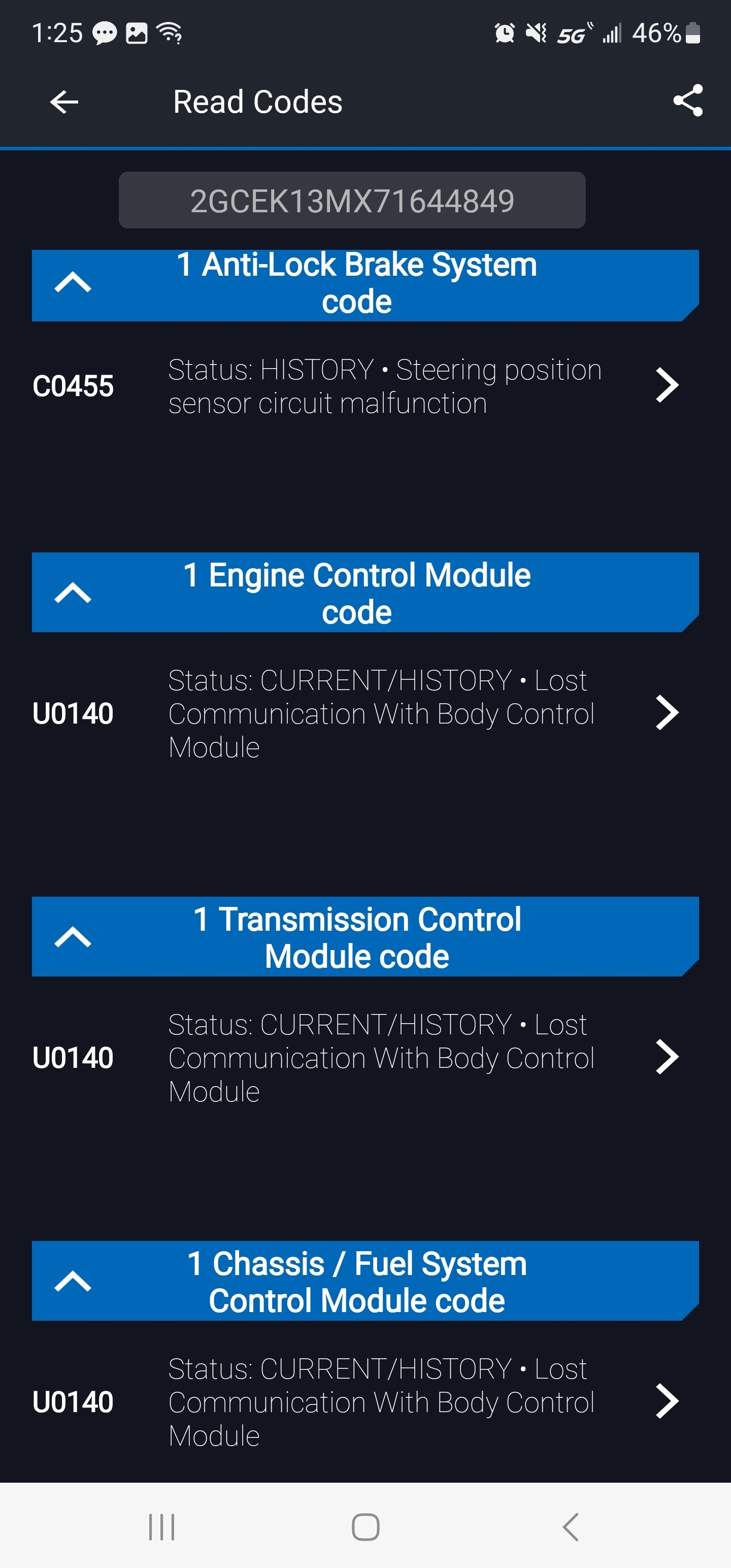
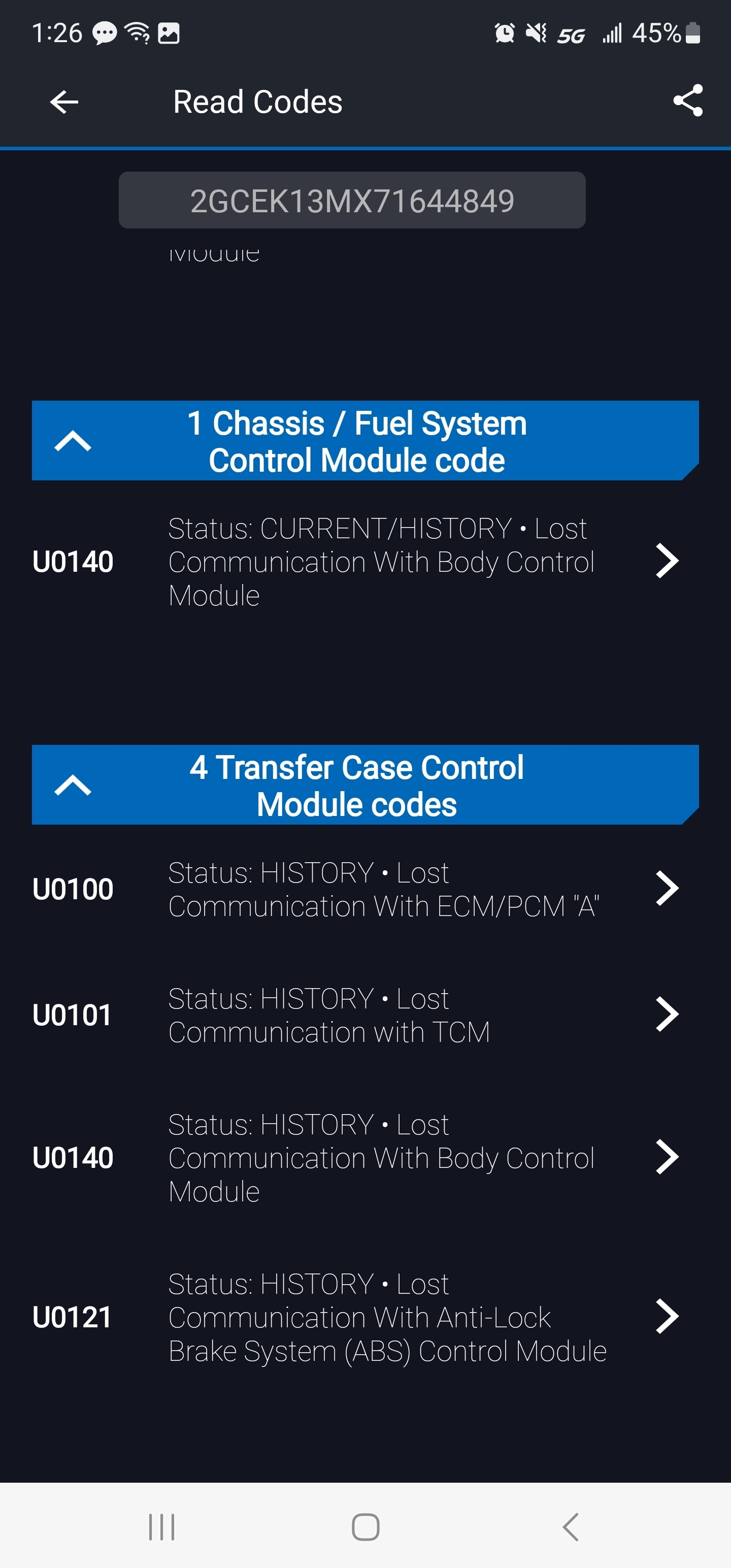
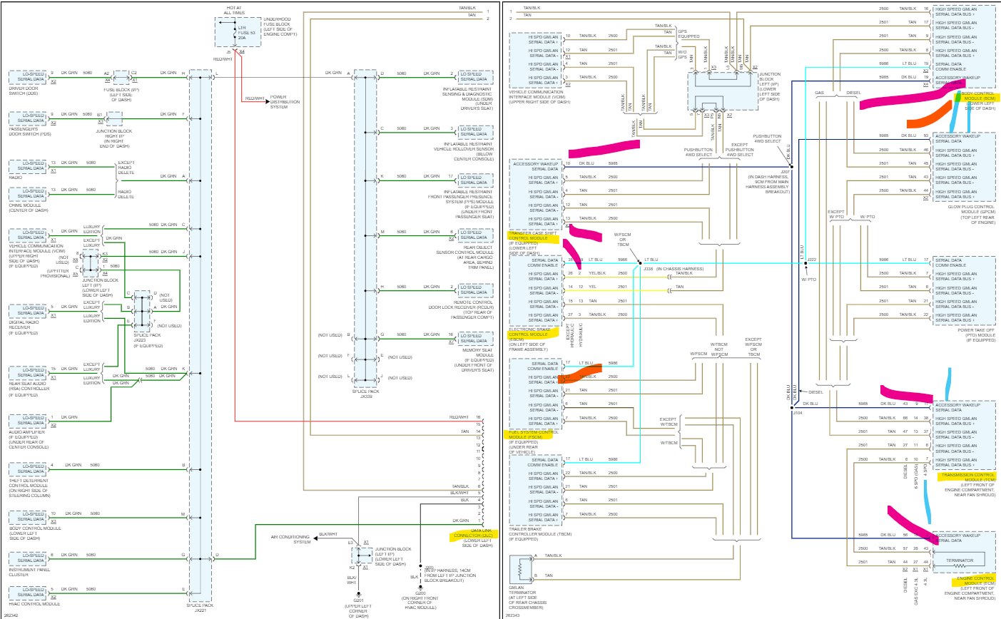
On your full system scan you should have had a long list of modules, but you only had 4. And there's 8 on the High speed and about 18 on the low speed. So, we see some missing for sure. But there are some checks you can do on the Data Link connector with a multimeter that will give us some good information to work with also. So, enjoy your weekend and I'll have some testing ready for you when you get back.

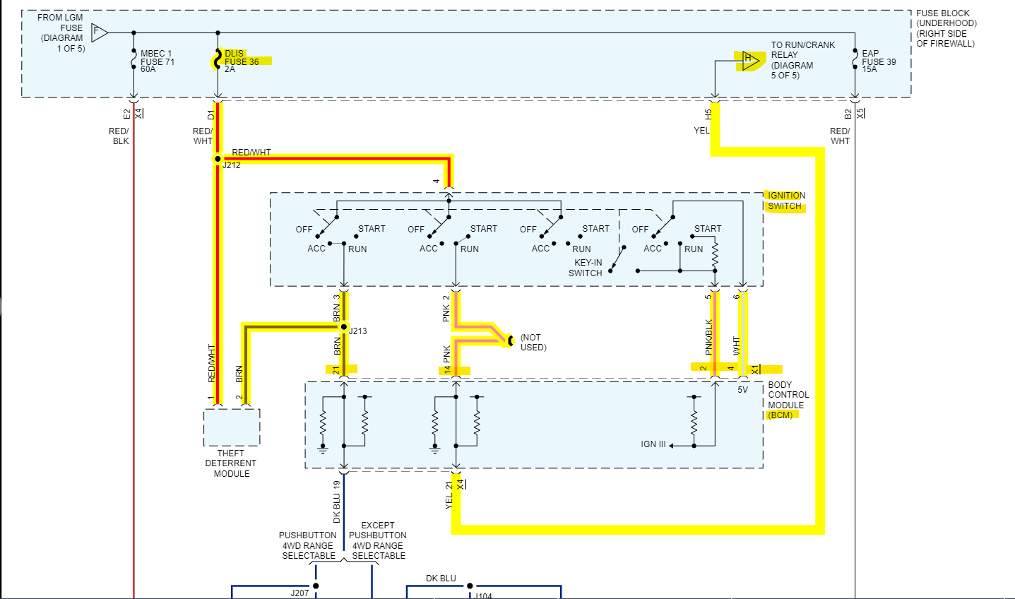
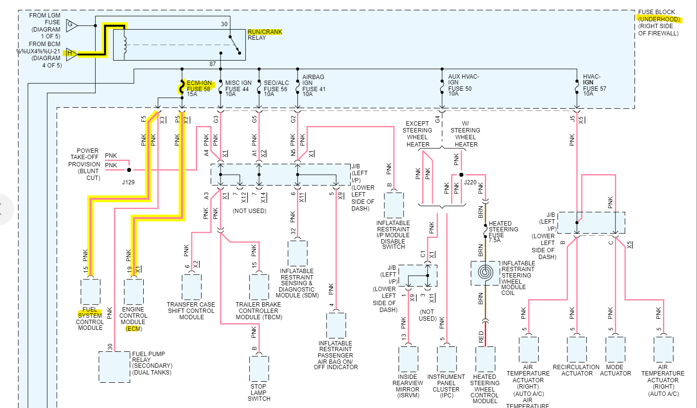
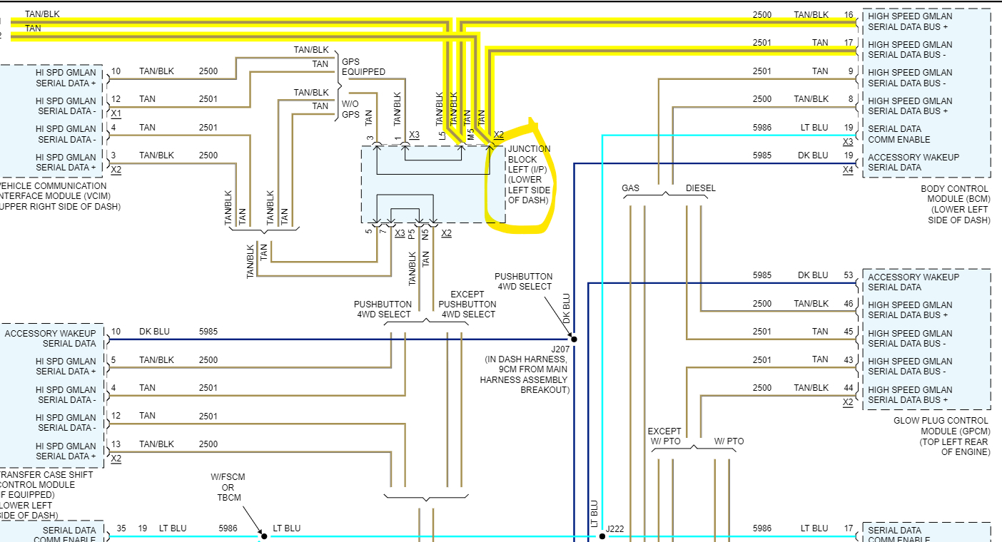
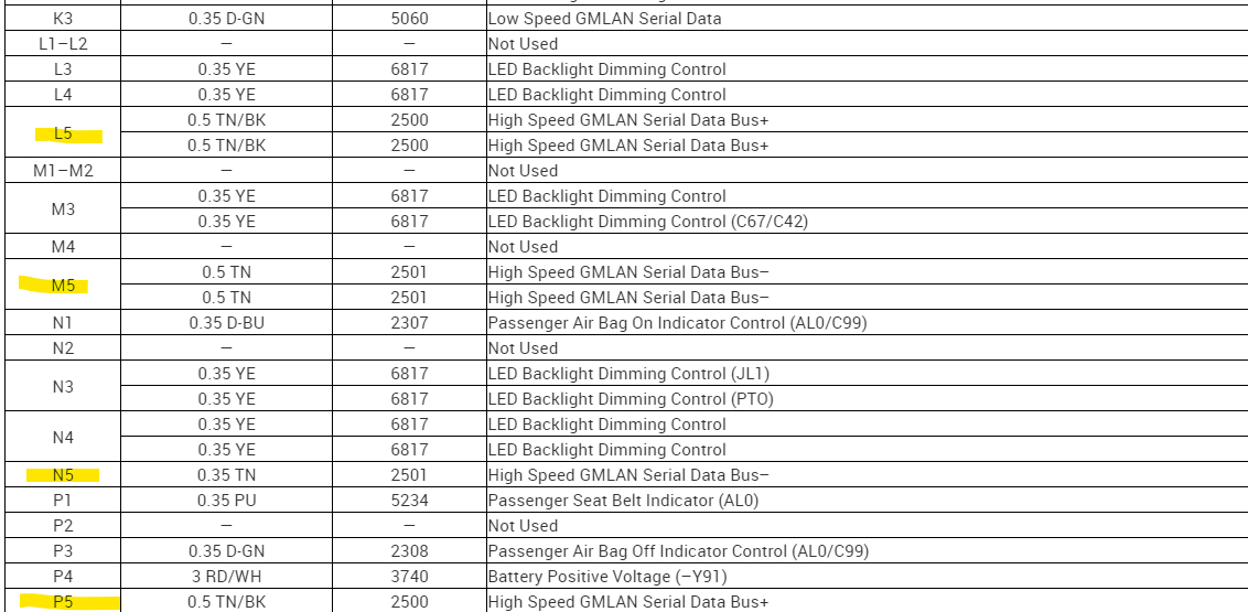
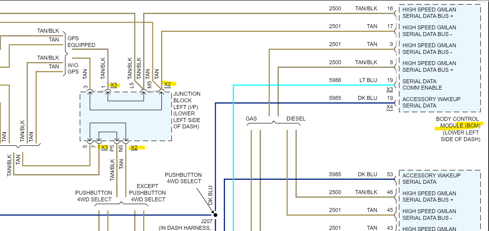
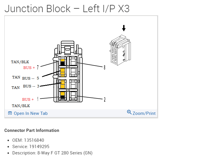
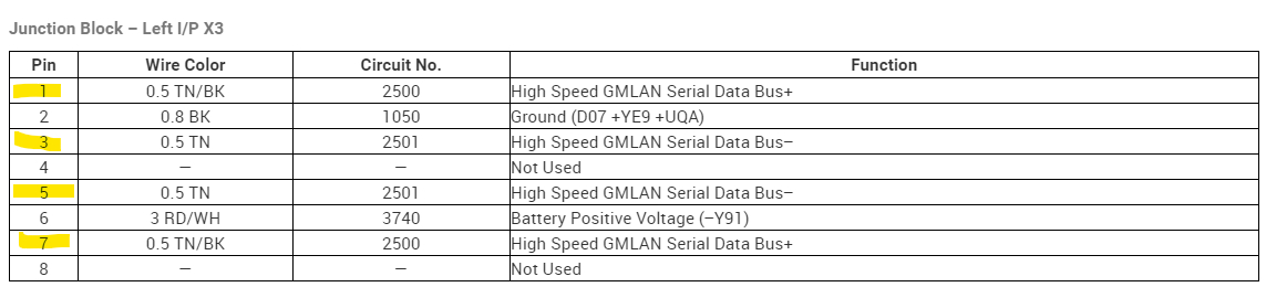
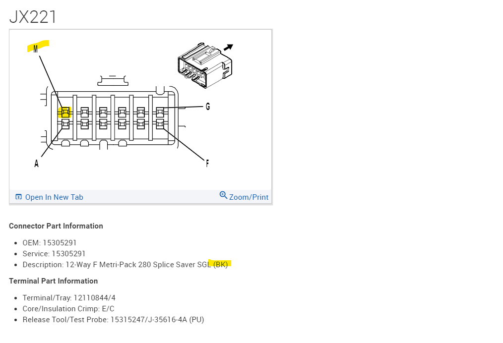
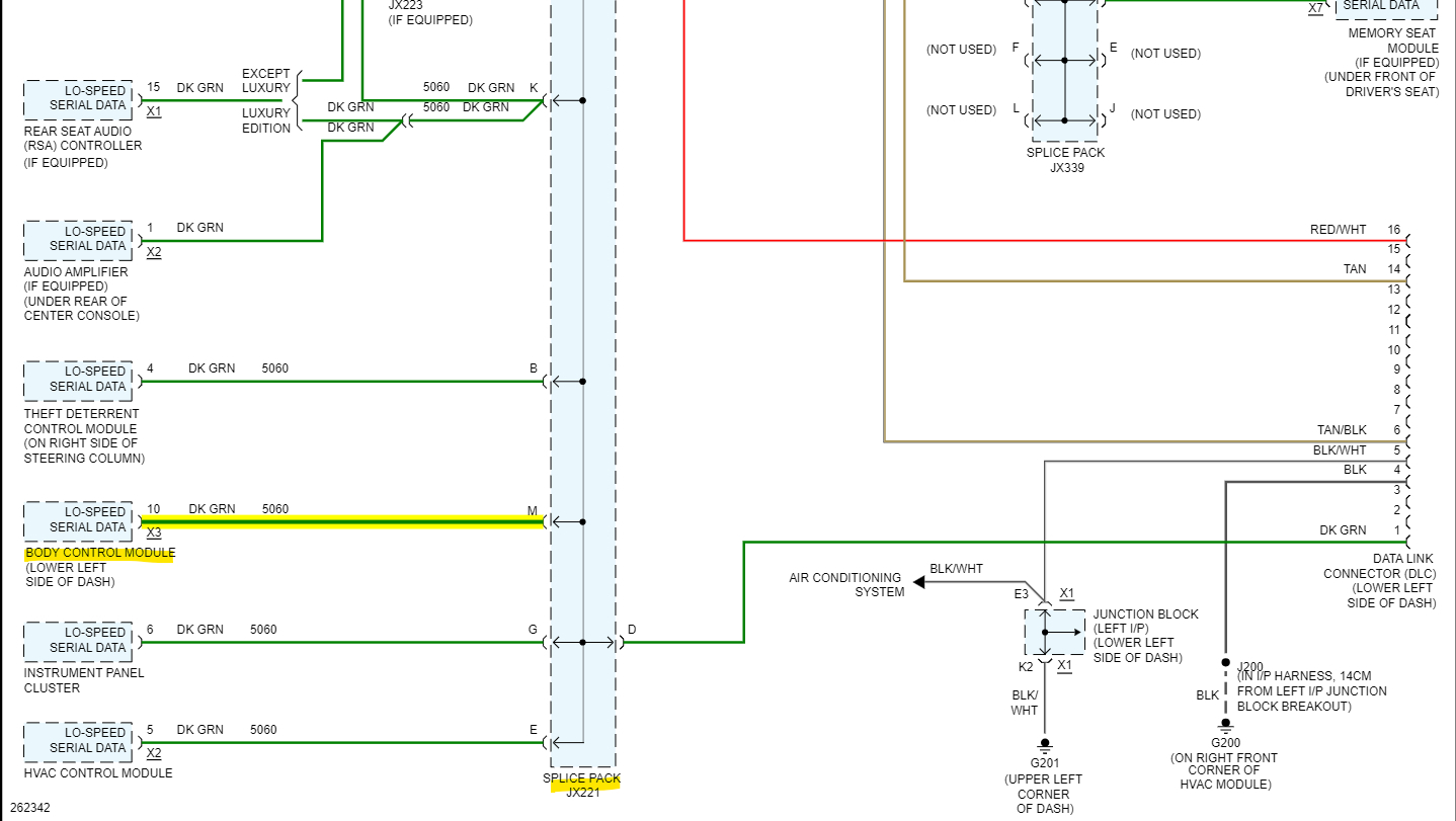
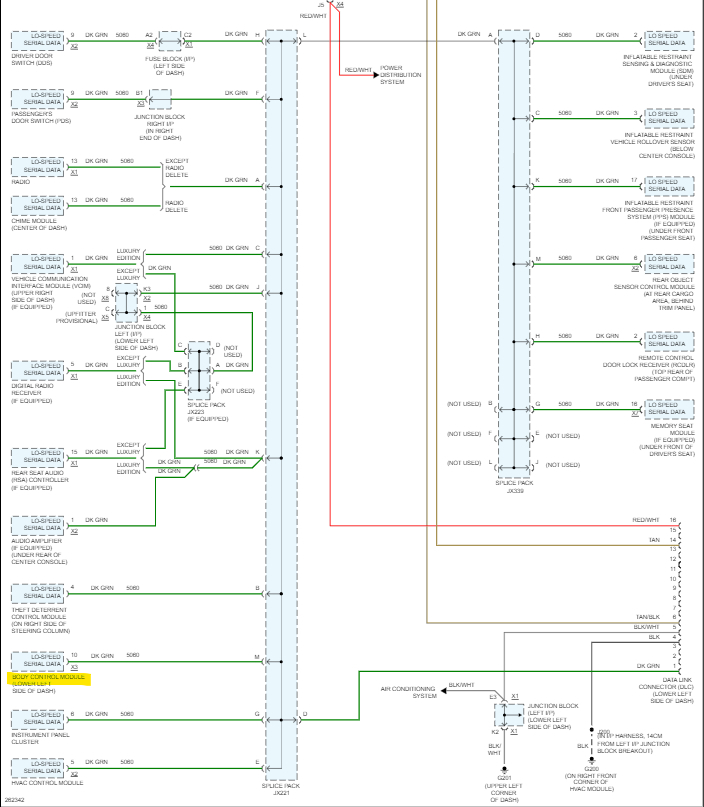
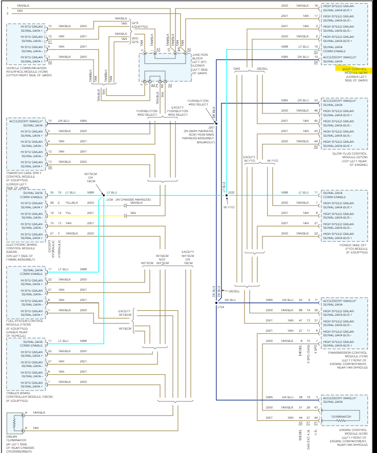
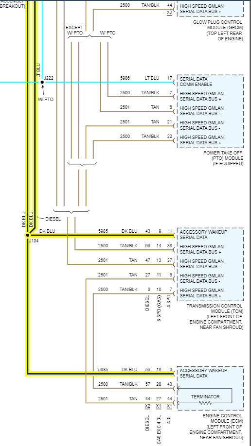
And yes, you are correct on the jx221, all the wires are green. There are actually 2 splice packs like that. Diagram 2 shows all the Low-Speed modules and diagram 3 is all the High-Speed modules. And the BCM is the gateway between the 2 networks, so you can see it being down causes all kinds of issues. Also, you can see the High-speed mods are all 2 wire network connections, GM calls is a GMLAN Serial Data bus, but its actually a CAN BUS type. Its 2 wires so if a circuit fault occurs most of the time messages can still get through for safety reasons. But only 4 out of all those modules is setting codes,
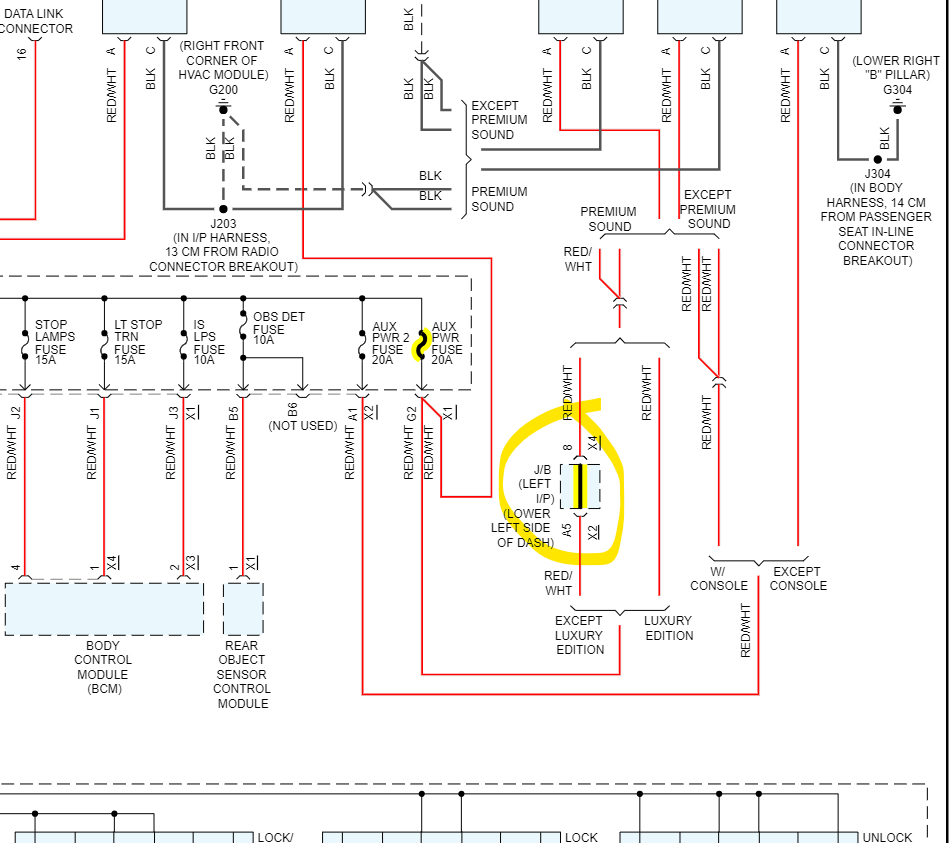
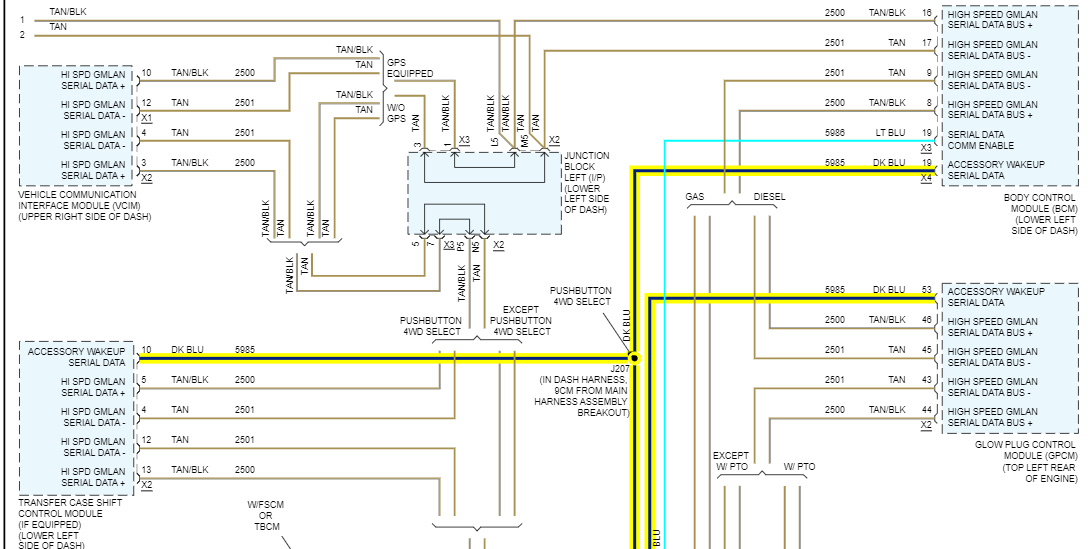
So, I'm wondering if the BCM is missing this Wakeup Serial Data message (diagrams 4, 5) or if its missing power or ground keeping it offline.

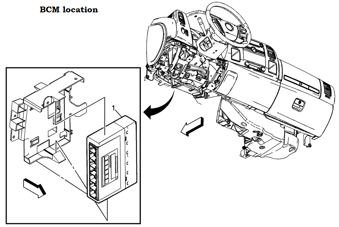
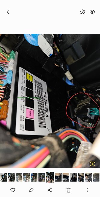
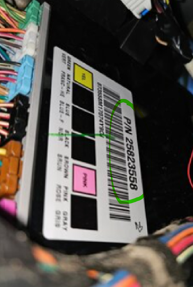
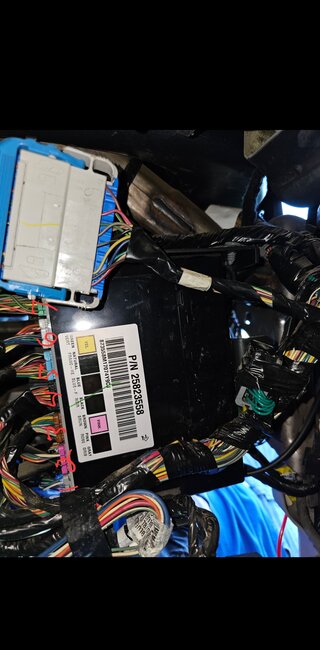
One last thing, I did a part number search, and this is the BCM in diagram 6, thanks for taking that picture, which helped a lot. Apparently this one only has 6 connectors, unless you see a 7th, but that is the correct part number for a 07 Chev Silverado 5.3L.
Was this
answer
helpful?
Yes
No
Saturday, August 12th, 2023 AT 10:31 AM
Tiny
JAVIERMLNDZ
  • MEMBER
  • 51 POSTS
I appreciate all the help! Forgive me I am very green at this lol! And yes, the BCM does have 7 connections.
Was this
answer
helpful?
Yes
No
Saturday, August 12th, 2023 AT 11:33 AM

Please login or register to post a reply.

Sponsored links