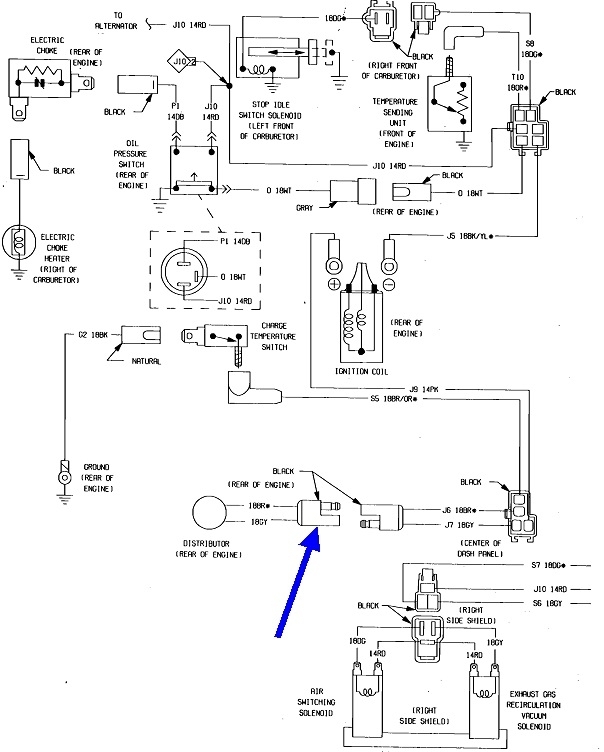
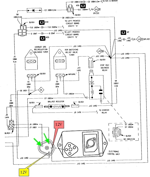
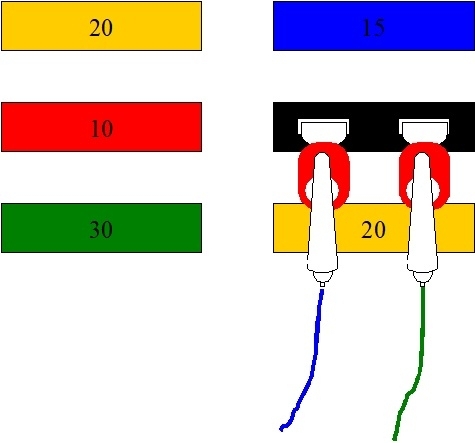
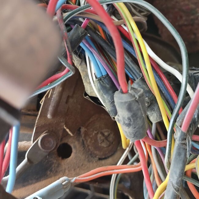
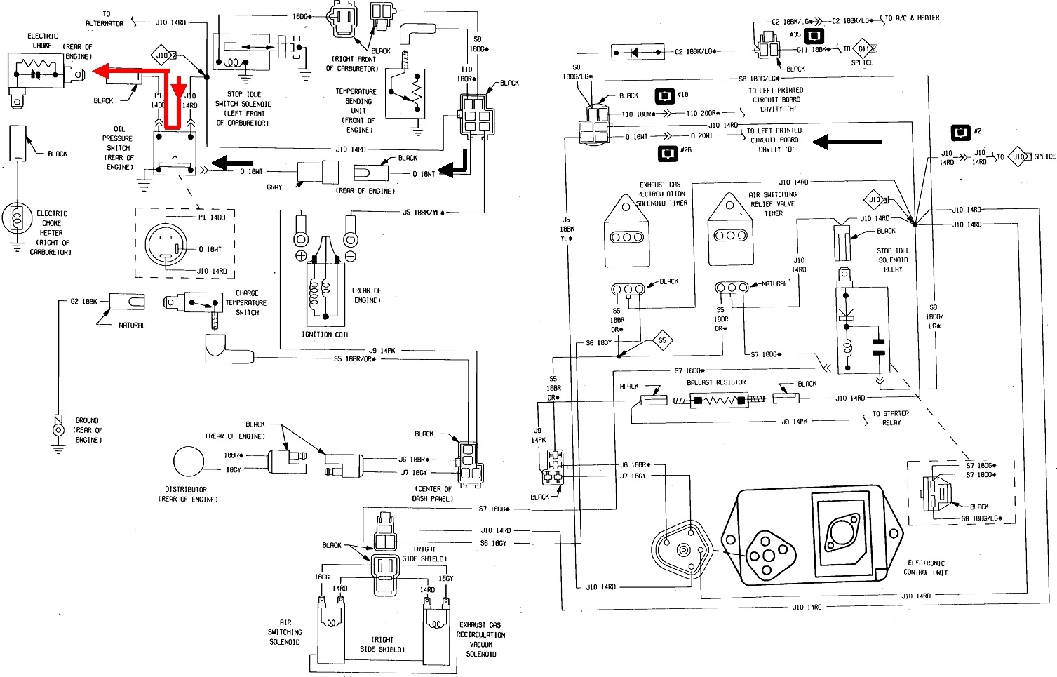
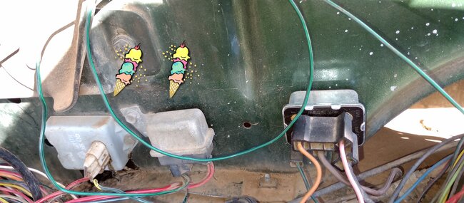
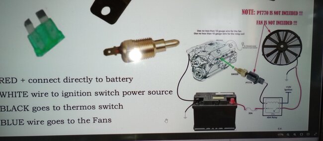
Here's the diagrams for your fan. I figured the red wire is the 12-volt feed for the fan, based on the fuse holder. I'm taking a guess the blue wire is the switched 12 volts going to the fan motor, so that's the color I used on the diagrams.
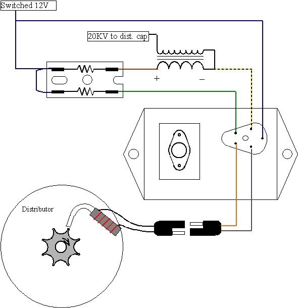
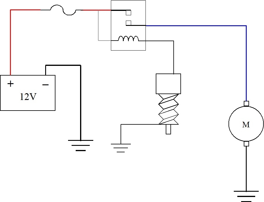
In the first diagram, the gray wire, (white on your relay socket), is connected to the red wire, and both are tied right to the battery positive circuit. This way, the relay will turn on and the fan will run any time the temperature switch turns on. The ignition switch doesn't have to be on. If the engine is hot when you turn it off, the fan will continue running, and it could start up unexpectedly if some heat migrates over to the sensor a minute or two after the engine is turned off.
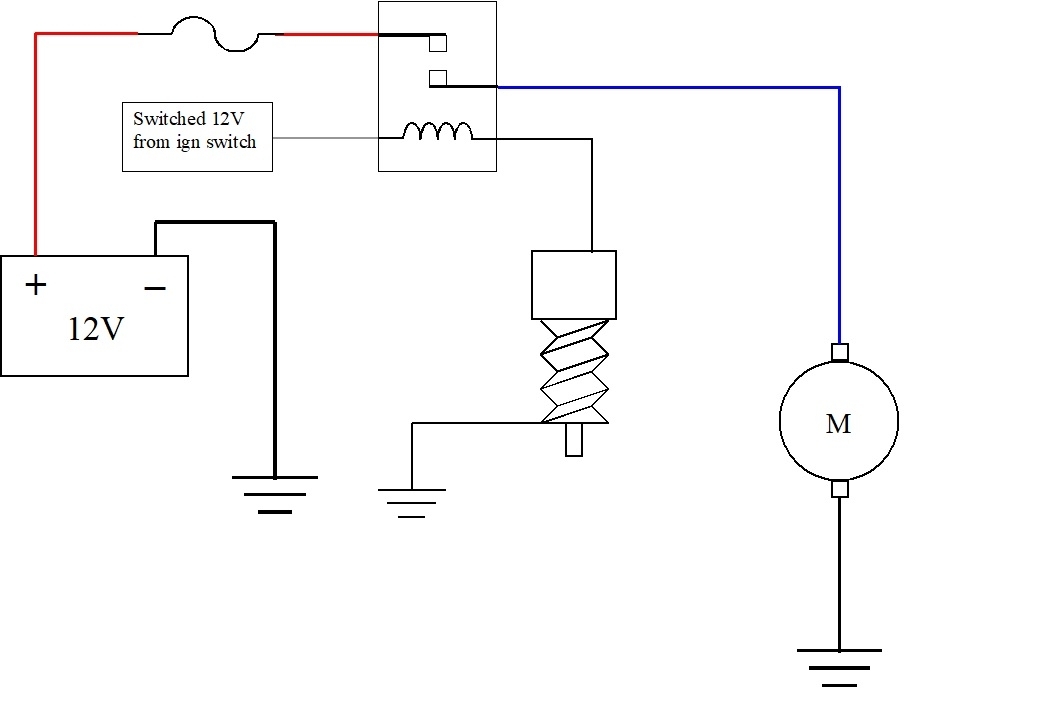
The only difference in the second diagram is that gray (white) wire is connected to a switched 12-volt source. That would include those red wires under the hood. This way the fan will only run if the ignition switch is on.
For the coil of the relay, again, I took a guess at the wire colors. Black is normally for ground circuits, so I drew that one going to ground through the temperature switch. That leaves my gray wire, (white) for the 12-volt supply. Once you decide how you want that wire to get its 12 volts, I need to add another clinker to insure there's sufficient confusion. All electromagnetic coils develop a magnetic field that takes a little time to build up. It's when the current is switched off that the field has no choice but to collapse instantly. Doing so causes it to generate a huge voltage spike, often as high as 300 volts. That's what we need to happen in an ignition coil, but for injectors, AC compressor clutches, and relays, those spikes can do a lot of damage, mainly to computer modules that are switching those things on and off. To prevent that from happening, something is usually added somewhere in the circuit to dampen or absorb those spikes. GM does that by placing a resistor across the coil. When a spike occurs, the resulting current flow goes through the resistor to just dampen, or reduce the voltage of that spike. The advantage is resistors don't have a polarity, so the coil can be connected either way. With their terminal basing, the relay can be installed two ways, as long as it will physically fit, and work just fine. The minor disadvantage is resistors don't totally eliminate the spike.
Chrysler, and most other manufacturers use a diode across the coil to totally eliminate voltage spikes. Diodes are one-way valves for electrical current flow. When 12 volts is applied to turn the relay on, the diode is "reverse-biased", meaning it is in there backward, is turned off, and acts like it isn't even there. When the relay is turned off, the spike occurs for an instant, then the diode is "forward-biased", meaning it acts like a piece of wire, and completely eliminates that spike. While this is more effective, it means the coil can not be connected either way like with the GM relays.
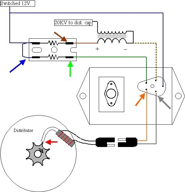
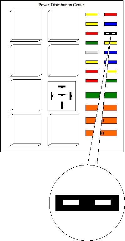
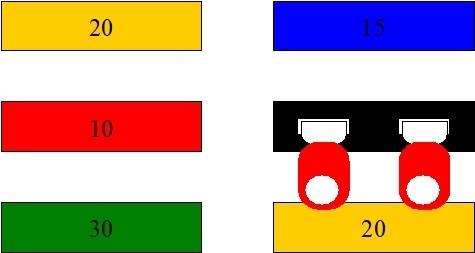
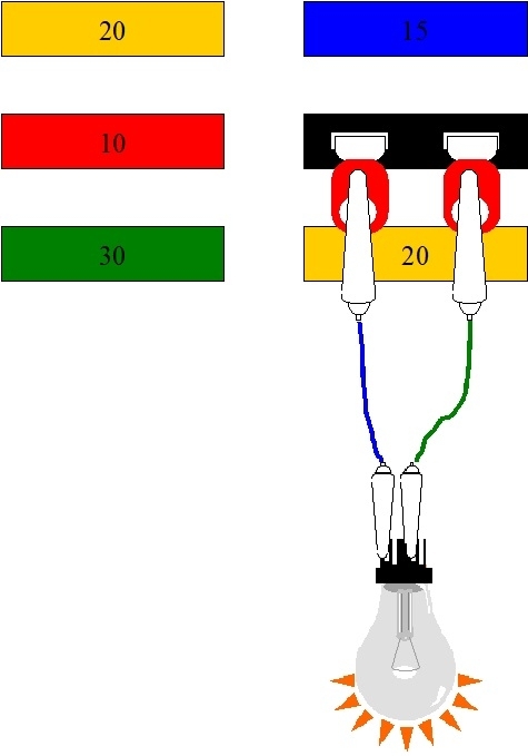
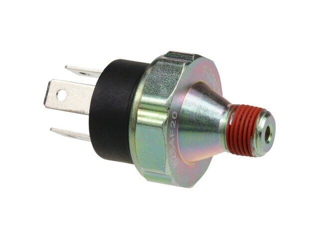
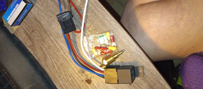
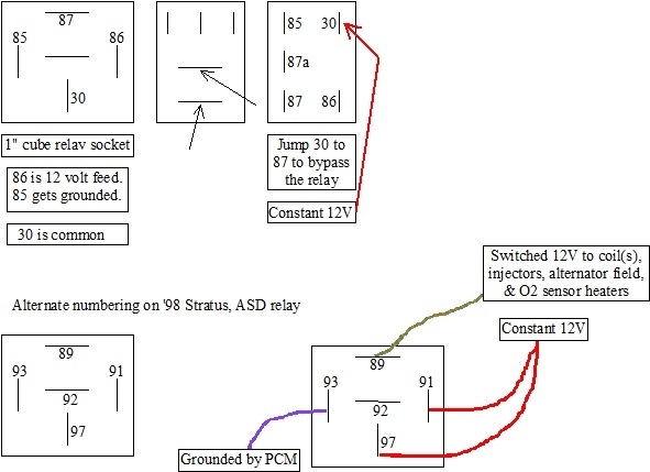
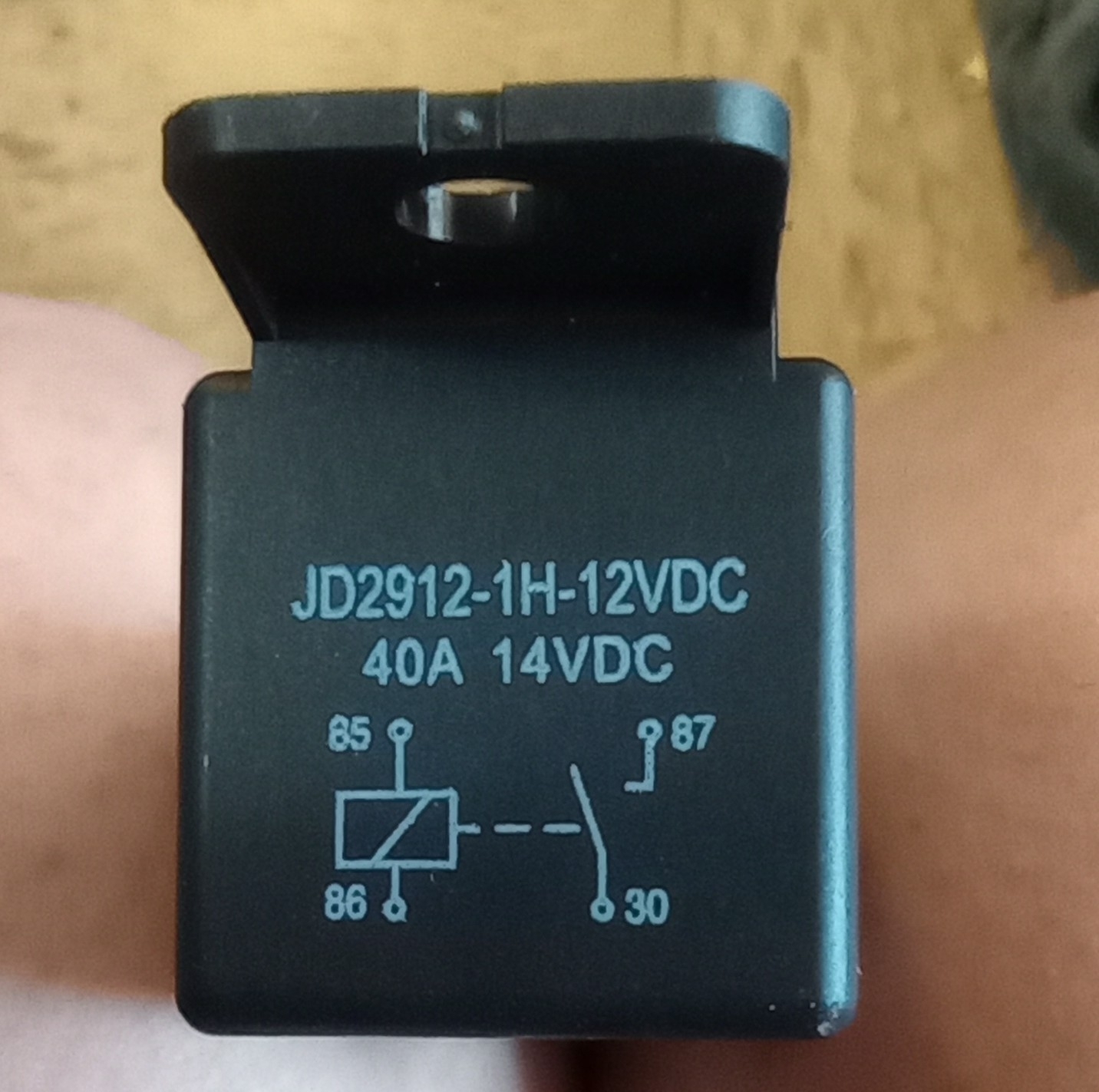
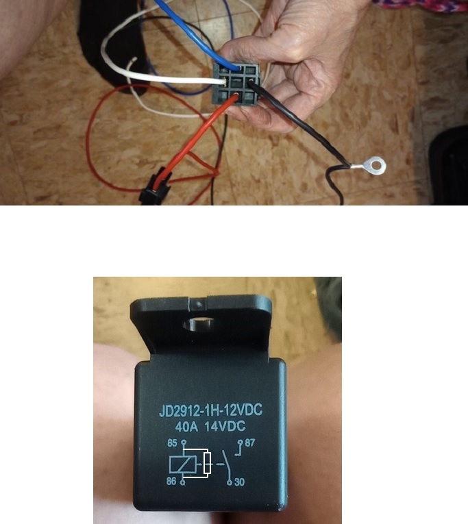
The best way to know how to connect the coil is with the instructions. This whole story is because you don't have them. Instead, start by looking on the relay's cover to see if they printed a little diagram on it. If there is one, try to post a photo of it. Also post one of the bottom of the socket where the wires come out. In my third drawing, this shows the terminal layout for some common relays. Yours most likely matches the top left one. The numbering I used is used by Chrysler and many other manufacturers, but you won't find those on generic aftermarket relays. I'll use those numbers simply for reference.
The middle terminal is 87a. It is rarely used, and may not even be on your relay. If you look at terminals 30 and 87, they form the letter "T". Those are the contacts that carry the high current to the motor. In this case, either terminal can be the red or blue wire.
Now, if I'm right, the black wire is the ground, or negative side of the coil, and the white wire is the positive, or 12-volt end. Those two should correspond to terminals 85 and 86 in my drawing. Those are parallel to each other. Before you go through the work of wiring the socket, then finding out it's wrong, we should verify the colors and polarity. Again, this assumes there's no drawing on the relay's cover.
I should pause here and add another comment of value. Given this is a generic, or universal relay, there may not be a diode across the coil. That would eliminate the need for this entire sad story. Also, since the coil is switched off by a physical switch, those are not affected by voltage spikes, so the diode is not needed in this application, making it further likely there is no diode in the relay. If there is indeed no diode in the relay, either terminal, 85 or 86, can go to the switch, and the other one can get the 12-volts.
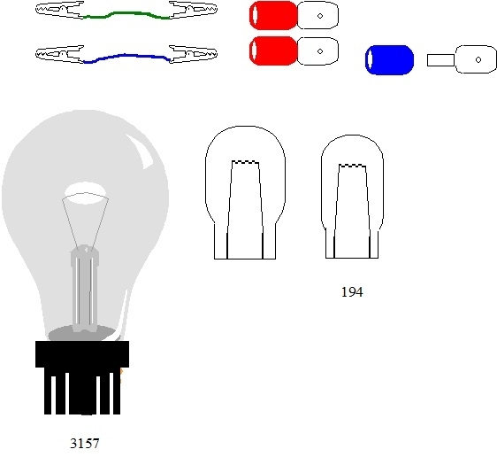
What I would do in this case is to simply connect the coil to 12 volts and feel if it clicks. I'd do this by connecting one terminal, 85 or 86, to the battery's negative post with a small clip lead or jumper wire. Then I'd use another clip lead connected to the battery's positive post, then quickly tap it to the other relay terminal and feel for the click. The reason I'd tap the clip lead briefly is if there is a diode in there, and it is forward-biased now, there's nothing to limit current flow. The relay will not click, and if the connection lasts too long, the diode is going to overheat and short. Usually they will burn open after that, then the short will be gone. The relay will work normally, but the spike suppression will be missing.
If the relay clicked, you know that polarity will work in the truck. If you want to be brave and experiment, switch the two clip leads to see if the relay will click with the opposite polarity. Tap the last wire briefly again and feel for the click. If you find that it clicks, there's no diode and terminals 85 and 86 can be connected with either polarity.
This is how I originally figured out how to wire the Chrysler relay, for a custom application, shown in the upper left of my drawings, when I didn't know which terminal was which. The problem is on my first attempt, the diode shorted and smoke came out of the relay. A simple way to avoid this is to add a small light bulb in series with one of the jumper wires. I can make a drawing to explain this better if you need me to. Connect one relay terminal to negative, as before. Connect the other terminal to one terminal of the light bulb. Connect the bulb's other terminal to positive. If the polarity is correct, or if there is no diode in the relay, the bulb will light up about half of normal brightness. It's using up roughly half of the 12 volts, or six volts, leaving the other six volts to run the relay's coil. For most relays that is enough and you'll feel it click. Some relays need more, so they won't click, but the dim bulb tells you the polarity is okay.
A good bulb for this is a small, 194 "peanut" bulb found in dash boards, and side marker and license lamps. It will only allow a maximum of a half amp to flow. It's easy to connect clip leads to the terminals.
Now switch the polarity and do this again. If the bulb is still half of normal brightness, the coil can be connected with either polarity. However, if you find the bulb is full brightness now, that proves there is a diode in the relay and it is forward-biased now. That means it's the wrong polarity and polarity is important.
Now that I shared all that wondrous confusion, let me make a better suggestion. When holding the socket with the terminals toward you and the wires on the back side, use terminal 86 in my drawing for the positive, or 12-volt feed side, and use terminal 85 to go to the temperature switch. The reason for this is it matches the industry standard for relays that do have a diode. Now, if your relay ever fails, you can find hundreds of replacements in any salvage yard. Chrysler has used a couple of other designs, as shown in my drawings, but the i" cube relay has been around since the late '80s, and is still being used today. You'll be able to plug in any relay from any application, without worrying whether it has a built-in diode.
Remember, this all assumes I have the correct wire colors on your socket. The terminals for the blue and red wires should form that letter "T". If I have that wrong, the story is the same, but the colors will have to be changed.
Images (Click to enlarge)
Mar 20, 2024 at 4:42 PM