Scopes are complicated, but necessary to diagnose modern or even older vehicles. The thing with learning to use an oscilloscope is just to dive right in, watch as many videos as possible, ask questions, and once you get the basic idea, you will wonder how you ever did without one. I didnt have anyone teach me, in fact when I was in college they didnt even train us on scope use. But when you can look at things such as ignition coil and fuel injector current waveforms and know if theres a shorted coil or lack of some other essential signal without even taking anything apart, it will save you all that time you spent trying to figure out what was going on with that last vehicle. Youre not going to get away from computers and sensors, its impossible. Even if you buy an S-10, it still has all the basic sensors of any older vehicle. But you cant spend 6 months trying to diagnose something, its frustrating on both ends.
I did watch this video on the OTC Genisys scope, if I spelled that right, but its pretty cool, Im surprised it has 4 channels, I have a small handheld scope like this thats only 2 channels that I use for quick checks on things.
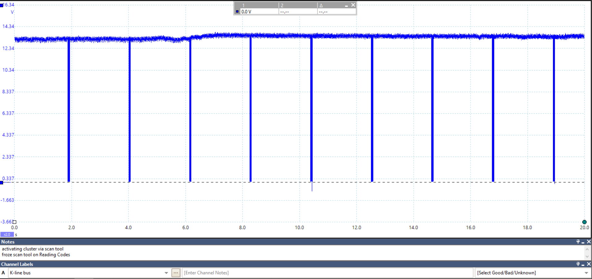
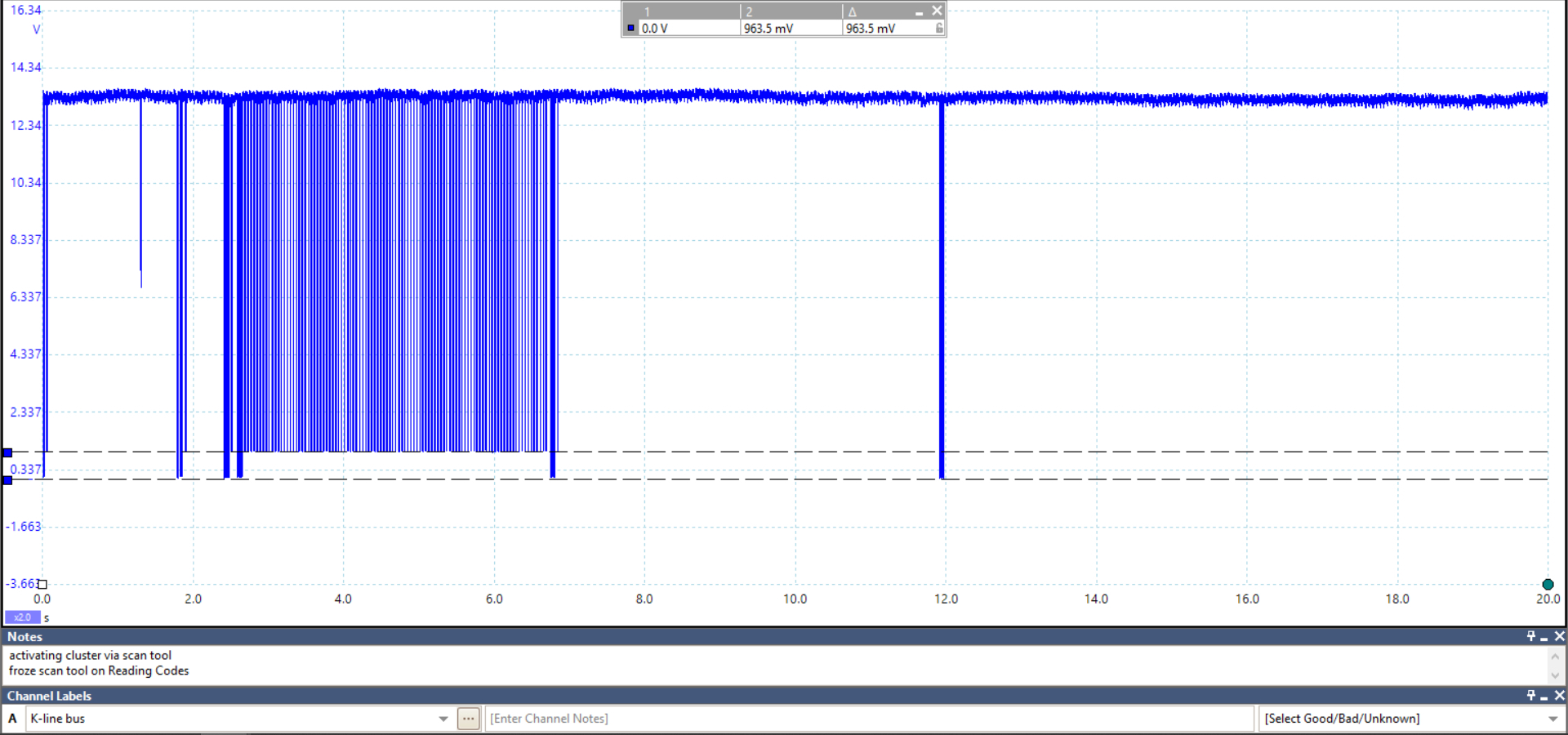
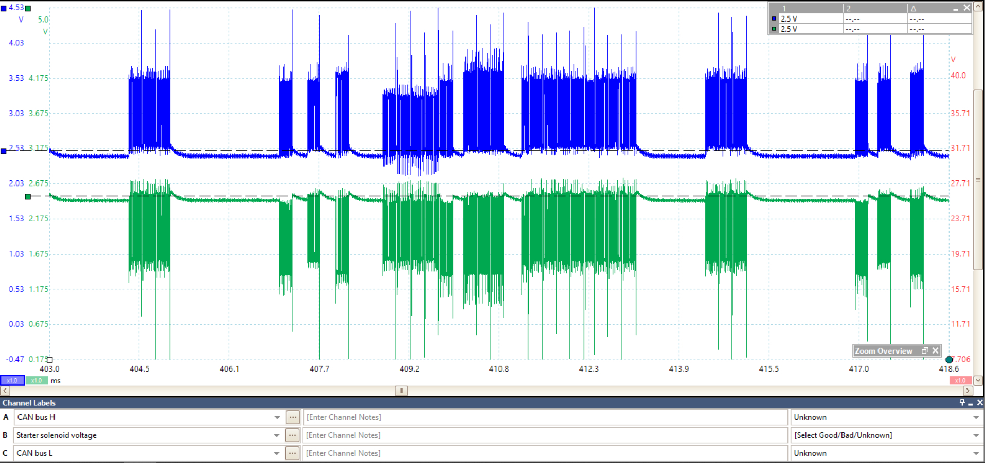
These are a couple of very simple waveforms I captured from a 2013 Hyundai Sonata, this is the K-Line network which is what is used for a scan tool to communicate with this particular vehicle. This vehicle has a fault with the instrument cluster, in the first picture the pulses are my scan tool trying to communicate with the cluster, except the cluster froze its communications when I tried to read codes from it, the 2nd picture (and you can see the difference in voltage levels here) is where the cluster finally responded. The 3rd picture is the vehicles Can Bus High speed network where you can see the voltage levels are all over the place. But there would be no way to know what was happening with the vehicle without a scope, the scan tool would just sit there with a frozen screen trying to read trouble codes and I would have had no idea what was wrong. Granted this is the technical side of things, but you could have checked your cam and crank signals in 5 minutes to see if they looked correct. Not even having to replace any parts until you know whats actually wrong, just the benefits of learning new things. I fully understand the hesitation of it all, buts its like everything else, once you learn it, you are ahead of all the guys that dont use this type of equipment and are just changing parts until they happen to fix something.
This is also the Pico 6 automotive software that has guided tests, tells you where and how to hook up the scope to the vehicle and what to expect for a waveform.
OTC Genisys scope video..
https://www.youtube.com/watch?v=g2IoPBWyEds
Images (Click to enlarge)
Jun 15, 2025 at 9:44 AM