Idle not low enough and rough

Tiny
CJA31186
  • MEMBER
  • 89 POSTS
Can I just follow the wiring used in the nutter bypass, or are we wiring it differently?
Was this
answer
helpful?
Yes
No
Thursday, May 18th, 2017 AT 11:25 AM
Tiny
CJ MEDEVAC
  • MECHANIC
  • 11,004 POSTS
Will this get you going?

The 1st pic is the "Standard" we are trying to achieve.

The Medic
Was this
answer
helpful?
Yes
No
Thursday, May 18th, 2017 AT 4:59 PM
Tiny
CJA31186
  • MEMBER
  • 89 POSTS
Thanks. This looks good, but I'm kind of lost between the 3 pictures. The middle one I understand, but the other two, are they showing additional wires that need to be cut and rerouted?
Was this
answer
helpful?
Yes
No
Thursday, May 18th, 2017 AT 6:50 PM
Tiny
CJA31186
  • MEMBER
  • 89 POSTS
Think I understand now. Purple black and orange get cut at the ignition module and rerouted directly to the same color wires at the distributor. The green wire gets cut at the module and rerouted directly to the green wire on the coil. The white wire from the module gets cut and rerouted directly to the S wire on the solenoid. Then finally the red wire does not get cut, but spliced into at the module, then with that splice gets connected to the red wire at the coil, with another splice from the red wire at the coil going directly to the "I" side of the solenoid. Is that correct? Am I missing anything with the blue wire needing to get spliced?
Was this
answer
helpful?
Yes
No
Thursday, May 18th, 2017 AT 7:29 PM
Tiny
CJ MEDEVAC
  • MECHANIC
  • 11,004 POSTS
Those additional wires are probably there, just running all over the place in wire looms before they set to their destination.

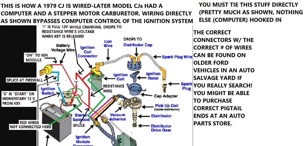
They are all the same in the 3 diagrams as far as the IGN module to the distributor
and
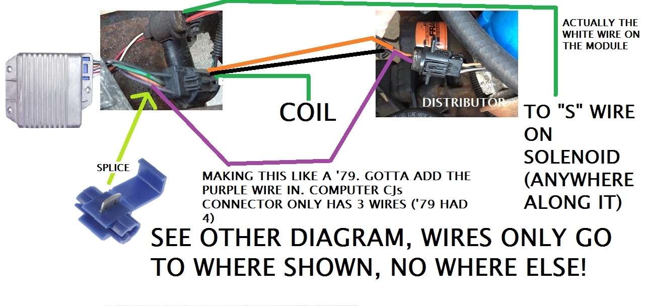
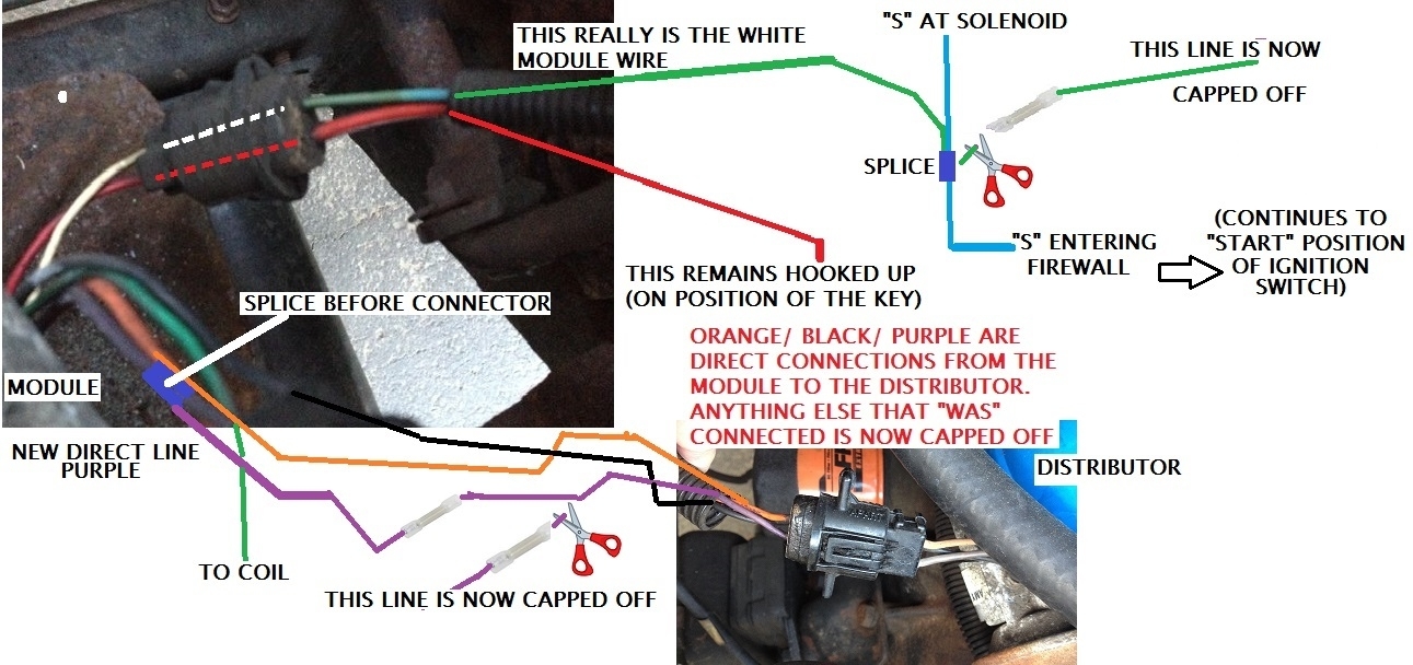
The IGN module to going to the "S" wire (follow the white one from the module body) The white wire turns to green thru the connector on "your" Jeep (consider it still being white as it continues). In Diagram 1 "White wires" are shown as thin black ones (usually labeled as white)

Look at 1st diagram, the white wire is white the whole way, and it connects to the "S" wire (blue) at the firewall (it COULD connect to to that blue wire anywhere, as long as it connects!)

As you try to duplicate the diagram, if you have to cut a wire loose to do this (such as keeping the purple wire from the distributor) (but getting rid of the other end going to the computer) Crimp one side of a butt splice onto that unneeded wire to keep it from touching stuff.

Now you can tie the purple to the IGN module's purple. Purple is now a straight shot to the distributor. IT GOES NO WHERE ELSE!

Make sure the other wires work out as a straight shot, disregard and half butt splice anything unneeded!

In the end, you should be able to look like diagram 1's Module set up.

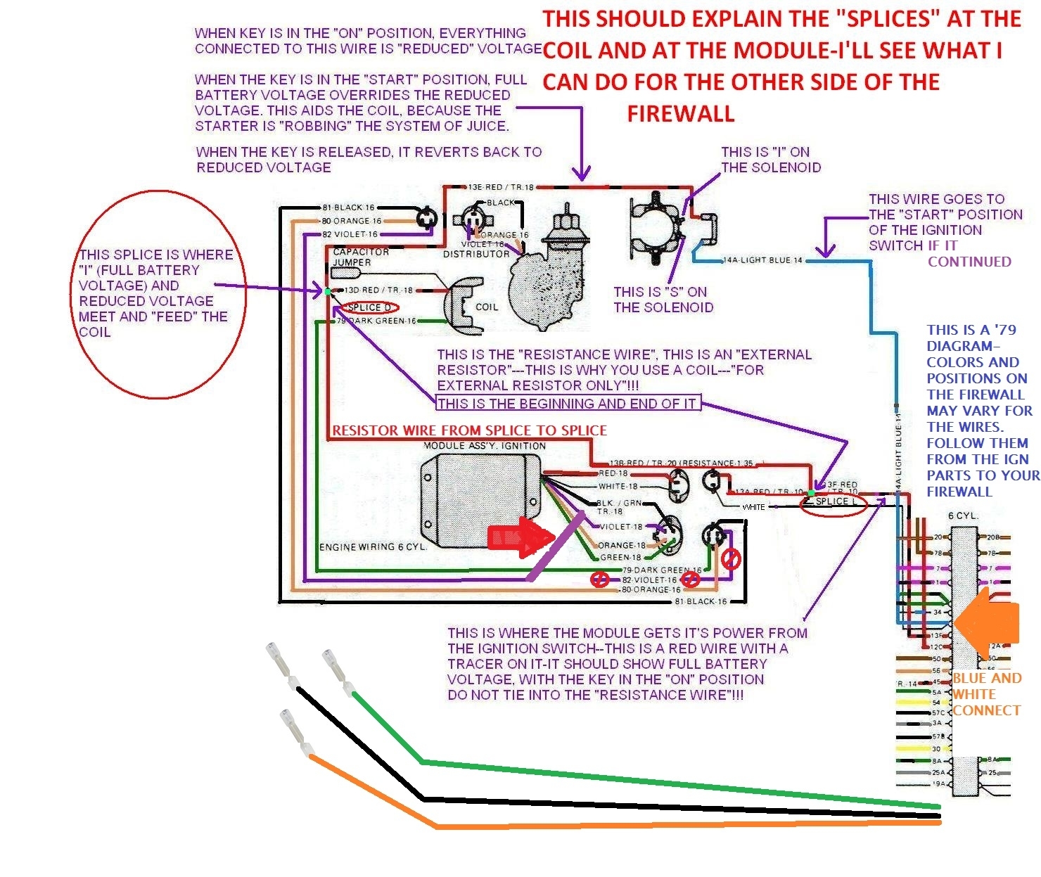
DISREGARD all of the other wires that I censored away at the firewall.

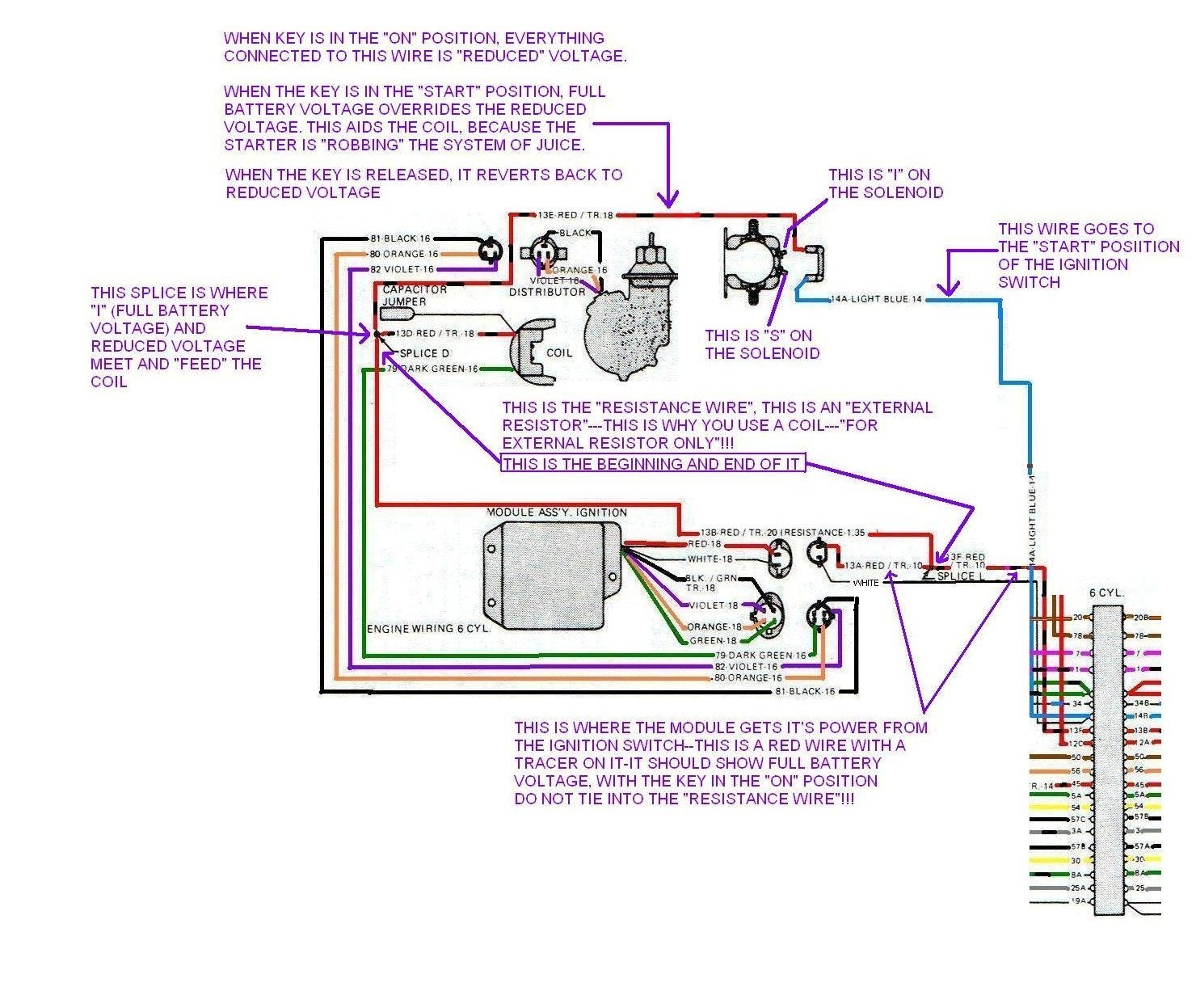
1st Diagram At the firewall I show a Red wire with a stripe (stripe color unknown) it runs to the IGN module 2 wire connector (this is a Regular Wire!). If you back up a hair from the module, you will see a splice.

The resistance wire starts here (it is a resistance wire, not a regular wire), it should still be part of your Jeep. Using the diagram, find it, KEEP IT! Do not tie anything else to it! Insure it runs up near the coil and splices into Regular wire!

So, basically 2 reg wires tie to the TEE near the module, along with the resistance wire

At the other end of the resistance wire, the resistance wire ties into a TEE with 2 regular wires (one to the coil, the other to "I" terminal of the Solenoid) ALL OF THAT OUGHTTA STILL BE ON YOUR JEEP, They may go around the world in wire looms to get there!

Lemme know if things on your Jeep are as in diagram 1, Straight shots to the appliances, anything else unused being 'capped off'.

YES, if you get lost, STOP and ask me!

Did any of that aid you at all, I do get carried away!

I'd rather you take pics, Draw pics, ask questions, instead of hooking something wrong and frying stuff.

The Medic
Was this
answer
helpful?
Yes
No
Thursday, May 18th, 2017 AT 7:56 PM
Tiny
CJ MEDEVAC
  • MECHANIC
  • 11,004 POSTS
WE ARE KEEPING the 3 wires!

The only mod to the IGN module is the splice onto the purple wire.

Your Black/ Green/ Orange wires will run as far as possible then get spliced onto where they go from the IGN module connector. Everybody else that deviates from the diagram gets whacked and capped!

Follow the purple from the distributor a distance, then connect it to the purple from the IGN module. Whatever you had to whack loose gets capped.

Try to keep this stuff "Loomed Up"and perty! No need in wires going every which-a-way!

The Medic
Was this
answer
helpful?
Yes
No
Thursday, May 18th, 2017 AT 8:06 PM
Tiny
CJA31186
  • MEMBER
  • 89 POSTS
So it sounds like the red wire is already set up the way it should be. Is that correct?
Was this
answer
helpful?
Yes
No
Thursday, May 18th, 2017 AT 8:12 PM
Tiny
CJA31186
  • MEMBER
  • 89 POSTS
When you say the orange, black, and green wires get spliced into, should I cut them then connect them directly to the same wires going to the distributor? Or splice into them still keeping the connections through the firewall?
Was this
answer
helpful?
Yes
No
Thursday, May 18th, 2017 AT 8:15 PM
Tiny
CJA31186
  • MEMBER
  • 89 POSTS
Maybe you misunderstood. I meant after the connection on the ignition module. Instead of those black green and orange wires going into the firewall, I would cut them and connect directly to the same color wires at the distributor. Is that correct?
Was this
answer
helpful?
Yes
No
Thursday, May 18th, 2017 AT 8:33 PM
Tiny
CJ MEDEVAC
  • MECHANIC
  • 11,004 POSTS
ROGER DODGER!

The green drops off at the Coil

Tie the Black and Orange into the wires before you get to the connector for the distributor. This will keep the distributor as a Removable Component by un-connecting it at the connector.

The Purple will generate from the purple wire on the Module with the splice shown in a previous diagram (Sorry, kinda the only way to get purple to be like a '79) (in order to replace the Module, it will have to be cut loose from the purple wire to the distributor harness).

Tie the purple into the 3 wire harness before the distributor connector.

The wires that did not show in the plan (diagram) the ones that you cut loose (leave a few inches), These will get one side of a butt splice squished on to them so they don't ground out (no need in even skinning them bare- they are now useless) Roll 'em up and tie them out of the way.

I played with my diagram some more.

Is this better?

Module to fender- break or drill out the holes.

You can remount it close to where it was with sheet metal screws. INSURE the module body is grounded!

The Medic
Was this
answer
helpful?
Yes
No
Friday, May 19th, 2017 AT 4:19 PM
Tiny
CJ MEDEVAC
  • MECHANIC
  • 11,004 POSTS
Diagram did not show/ here goes again

The Medic
Was this
answer
helpful?
Yes
No
Friday, May 19th, 2017 AT 4:26 PM
Tiny
CJA31186
  • MEMBER
  • 89 POSTS
Wires on hold until I get this ignition module out, and the new one in. Had no time this weekend, but will update as soon as I finish the wires and module.
Was this
answer
helpful?
Yes
No
Sunday, May 21st, 2017 AT 7:57 PM
Tiny
CJ MEDEVAC
  • MECHANIC
  • 11,004 POSTS
Roger!

Mine's down till Tuesday.

The too good to be true chrome valve cover was thin and brittle.

Could hear my rocker arms 30 feet away. Rear bolt hole's surrounding metal just popped out like a paper hole punch! (It was not over-tightened!)

The hidden oil flow down the back resembled a massive rear main seal leak.

Presently gonna clean up/ paint the old one, install new rockers/ pivots/ push rods just for giggles. (Hopefully gain some quiet and longevity).

I'll try to get some pics.

You should be getting close!

The Medic
Was this
answer
helpful?
Yes
No
Sunday, May 21st, 2017 AT 8:39 PM
Tiny
CJA31186
  • MEMBER
  • 89 POSTS
Ok so just to make sure, after the connection piece is connected to the ignition module, I cut the white wire, attach a wire connector piece then put a new wire into the connection piece and connect the white wire into the wire that goes to the s on the solenoid. Is that correct? Do I leave the wire that goes to the "s" side of the solenoid uncut so that it continues with the old connection in addition to getting the white wire connected to it? Or do I also cut the wire going to the "s" side of the solenoid so that it only connects to the white wire coming from the module?
Was this
answer
helpful?
Yes
No
Wednesday, May 24th, 2017 AT 6:12 PM
Tiny
CJ MEDEVAC
  • MECHANIC
  • 11,004 POSTS
"S" basically is the "Start Position" of the key. It has to continue to do it's original job!

You will tie the white wire into it (meaning the continuation of the white wire from the module)

Made you another diagram below.

So far you follow directions well (Like don't do nuthin' you are unsure of!)

This diagram help any better?

The Medic
Was this
answer
helpful?
Yes
No
Wednesday, May 24th, 2017 AT 8:50 PM
Tiny
CJA31186
  • MEMBER
  • 89 POSTS
Ok I completed all the wire and installed new module. New carb is on too. Turned mixture screws 3 turns out from the seated position. Jeep started right up with the new wiring and vacuum routing. It's not even tuned yet and it's already running excellent! Very smooth. So, what do I do now to tune the engine correctly?
Was this
answer
helpful?
Yes
No
Friday, May 26th, 2017 AT 6:15 PM
Tiny
CJ MEDEVAC
  • MECHANIC
  • 11,004 POSTS
WOW!

YOU ARE DOING GREAT!

This is gonna be EZ on me!

It's one that I answered back in 2010 (I was just a member, with no higher status yet). It may lack the 'smoothness' of the way I write now-a-days (If I can even say that!)

I noticed that the CJs (and many other vehicles) were receiving mostly 'Plain Jane' "textbook". "Generic" type answers. This was not always the case, But it seemed that the 'asker' would accept the answers even though he remained in the dark as to how to perform the tasks.

I reckon I could sense their frustration as they usually didn't return for more.

SO,

I sorta made it my mission to, at minimum, do all I could to help out the CJ guys and gals when they showed up, I try to help other's if I can, but my heart lies with the CJs!

I'm not Mr. AMC technician, nor do I know much about aftermarket modifications, numbers, ratios, horsepower, etc.

What I do have to offer is about 36 years of owning 5 CJs (and one Willys). Let me clarify that, Repairing, rebuilding 'My Own" stuff out of lack of fundage necessity. (I pretty much started out with nothing, and still have most of it left!). I tried to always gather CORRECT information and hands on experience is kinda my resume.

As I got educated more and more, Word spread that I was "The Man". I did house calls and they'd just show up at my house for various problems. In most cases, I'd make them do their own work, explain things, and step in here and there for "show and tell". 99% of the time they were grateful and now are VERY PROUD that they can DIY with that little push I gave 'em!

OK,

The only "UPDATE" I can do to this link is:

LEAVE YOUR DISTRIBUTOR'S VACUUM ADVANCE VACUUM LINE ATTACHED TO ***PORTED VACUUM*** on the carb!

https://www.2carpros.com/questions/jeep-cj7-1985-jeep-cj7-stalls-when-hot

I sorta translated this from 'My 258' to his '304' because I did not have a 304 to demonstrate with!

All you will have to do is leave out the 304 part!

Again,

Any questions, STOP, and ask me here!

Return with some SUPER good news!

How'd you like the "little scissors' I stuck in the last diagram?

The Medic

Was this
answer
helpful?
Yes
No
Friday, May 26th, 2017 AT 11:52 PM
Tiny
CJA31186
  • MEMBER
  • 89 POSTS
Yeah the scissors were a nice touch. Couldn't make it any more clear than that. Thanks! So I'm timing the engine to -9 BTDC at 700 RPM's right?
Was this
answer
helpful?
Yes
No
Saturday, May 27th, 2017 AT 5:56 AM
Tiny
CJA31186
  • MEMBER
  • 89 POSTS
Air cleaner assembly is off, but the ported vacuum remains connected right?
Was this
answer
helpful?
Yes
No
Saturday, May 27th, 2017 AT 5:58 AM
Tiny
CJ MEDEVAC
  • MECHANIC
  • 11,004 POSTS
Timing

Disconnect ported vacuum AT THE 'STRIBUTOR

Plug the hose with a BOLT/ PENCIL/ ETC.

TIME

IF RPM CHANGES

Back it back down to 700 RPM (this keeps the mechanical advance weights inward in the bottom of the distributor) If RPM is higher, the weights sling out and AUTOMATICALLY moves your timing (WE NO WANTY THAT TO HAPPEN WHILE TIMING!)

TIME AGAIN

Your finished product will be 9 degrees BTDC at 700 RPM

Tighten the hold down fork

PUT THE VACUUM HOSE BACK ON THE DISTRIBUTOR!

J
J
J

Wanna see if the 2 advances work? Now and in the future should you lack power and pick-up?

FOR THE MECHANICAL ADVANCE

Remove and plug the distributor vacuum line

Fire it up, your timing light should show 9 degrees on the timing cover (@700)

Watch the light while giving it gas on the carb

The timing mark should be getting further and further from the 9 degrees, let off of the gas and it should return to 9 degrees

IF BY CHANCE the spring for the centrifugal weights broke or something got stuck, the weights will permanently be outward, your timing will be well before the 9 degrees and will not change with engine speed as it should. Your engine will sorta hold back while driving.

If you ever experience the broke spring, Checking your timing and NOT noticing it's not on 9 degrees, you might think it got moved from moving the distributor. SO YOU IGNORANTLY move it back to 9 degrees. The spring is still broken! And you still have no advance!

The EZist fix is another re-manufactured Distributor!

Put the hose back on!

OK

VACUUM ADVANCE for the distributor

Hook up the timing light

Run a TEMPORARY Manifold Vacuum line close to the 'distributor (sucks constantly)

Fire it up and watch the light as you connect and disconnect the manifold vacuum to the distributor port.

You will notice engine speed will increase and the timing mark will move further back, then return when you take the hose off. The little arm coming out of the 'bell' and into the 'stributor will move too.

How's it a lookin'?

The Medic
Was this
answer
helpful?
Yes
No
Saturday, May 27th, 2017 AT 1:28 PM

Please login or register to post a reply.

Sponsored links