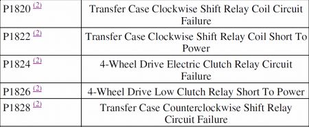
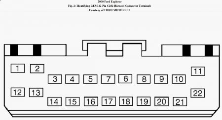
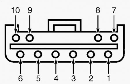
All these codes are for Transfer case relays, and are GEM only codes, I believe your GEM was installed incorrectly...55. Check Transfer Case Relays Monitor GEM PIDs MTR_CCW and MTR_CW. Toggle active command CW/CCW on, and then off. If PIDs MTR_CCW and MTR_CW indicate ON---, OFF---, go to step 64 . If PIDs MTR_CCW and MTR_CW display ON-B-, go to step 61 . If PIDs display OFFO-G, go to next step. 56. Check Voltage At Transfer Case Shift Relay Coil Circuit 705 (Light Green/Orange Wire) Turn ignition off. Disconnect transfer case shift relay connector. See Fig. 1 . Using DVOM, measure voltage of Light Green/Orange wire between ground and terminal No. 5 on shift relay harness connector. See Fig. 9 . If voltage is 10 volts or less, repair open Light Green/Orange wire. Clear DTC and retest system. If voltage is more than 10 volts, go to next step. Fig. 9: Transfer Case Shift Relay Harness Connector Terminals Courtesy of FORD MOTOR CO. 57. Check Circuit 513 (Brown/Pink Wire) For Open Disconnect GEM 22-pin connector. See Fig. 1 . Using ohmmeter, measure resistance of Brown/Pink wire between terminal No. 9 on shift relay harness connector and terminal No. 17 on GEM harness connector. See Fig. 2 and Fig. 9 . If resistance is less than 5 ohms, go to next step. If resistance is 5 ohms or greater, repair open Brown/Pink wire. Clear DTC and retest system. 58. Check Circuit 339 (Gray Wire) For Open Measure resistance of Gray wire between terminal No. 8 on shift relay harness connector and terminal No. 16 on GEM harness connector. See Fig. 2 and Fig. 9 . If resistance is less than 5 ohms, go to next step. If resistance is 5 ohms or greater, repair open Gray wire. Clear DTC and retest system. 59. Check Circuit 513 (Brown/Pink Wire) For Short To Ground Measure resistance between ground and terminal No. 9 on shift relay harness connector. See Fig. 9 . If resistance is more than 10 k/ohms, go to next step. If resistance is 10 k/ohms or less, repair Brown/Pink wire for short to ground. Clear DTC and retest system. 60. Check Circuit 339 (Gray Wire) For Short To Ground Measure resistance between ground and terminal No. 8 on shift relay harness connector. See Fig. 9 . If resistance is more than 10 k/ohms, go to step 63 . If resistance is 10 k/ohms or less, repair Gray wire for short to ground. Clear DTC and retest system. 61. Check Circuit 339 (Gray Wire) For Short To Power Ensure ignition is off. Disconnect GEM 22-pin connector and transfer case shift relay connector. See Fig. 1 . Turn ignition on. Measure voltage between ground and terminal No. 8 on shift relay harness connector. See Fig. 9 . If voltage is not present, go to next step. If voltage is present, repair Gray wire for short to voltage. Clear DTC and retest system. 62. Check Circuit 513 (Brown/Pink Wire) For Short To Power Measure voltage between ground and terminal No. 9 on shift relay harness connector. See Fig. 9 . If voltage is not present, go to next step. If voltage is present, repair Brown/Pink wire for short to voltage. Clear DTC and retest system. 63. Check Transfer Case Shift Relay Coils Turn ignition off. Using ohmmeter, measure resistance between terminal No. 5 and terminals No. 8 and 9 on transfer case shift relay connector. If resistance measured for both circuits is 60- 100 ohms, replace GEM. Clear DTC and retest system. If resistance measured for both circuits is not 60-100 ohms, replace transfer case shift motor relay. Clear DTC and retest system. 64. Check Voltage To Transfer Case Shift Motor Turn ignition off. Disconnect transfer case 16-pin connector. Turn ignition on. Using NGS tester, set active command CW/CCW to ON. Using DVOM, measure voltage between ground and terminals No. 14 and 15 on 16-pin harness connector. See Fig. 5 . If voltage is more than 10 volts, go to step 66 . If voltage is 10 volts or less, go to next step. 65. Check Voltage To Transfer Case Shift Relay Circuit 704 (Dark Green/Light Green Wire) Switch Side Turn ignition off. Disconnect transfer case shift relay. See Fig. 1 . Measure voltage between ground and terminal No. 3 (Dark Green/Light Green wire) on shift relay harness connector. See Fig. 9 . If voltage is more than 10 volts, go to step 70 . If voltage is 10 volts or less, repair open Dark Green/Light Green wire. Clear DTC and retest system. 66. Check Voltage To Transfer Case Shift Motor Turn ignition on. Using NGS tester, set active command CW/CCW to OFF. Using DVOM, measure voltage between ground and terminals No. 14 (Orange wire) and 15 (Yellow wire) on transfer case 16-pin harness connector. See Fig. 5 . If voltage is 10 volts or less, go to step 69 . If voltage is more than 10 volts, go to next step. 67. Check Circuit 777 (Yellow Wire) For Short To Power Turn ignition off. Disconnect transfer case 16-pin connector transfer case shift relay. Turn ignition on. Measure voltage between ground and terminal No. 15 (Yellow wire) on transfer case 16-pin harness connector. See Fig. 5 . If voltage is present, repair Yellow wire for short to voltage. Clear DTC and retest system. If voltage is not present, go to next step. 68. Check Circuit 778 (Orange Wire) For Short To Power Measure voltage between ground and terminal No. 14 (Orange wire) on transfer case 16-pin harness connector. See Fig. 5 . If voltage is present, repair Orange wire for short to voltage. Clear DTC and retest system. If voltage is not present, replace transfer case shift relay. Clear DTC and retest system. 69. Check Circuits 777 (Yellow Wire) & 778 (Orange Wire) For Open Through Transfer Case Relay Set active command CW/CCW to OFF. Using ohmmeter, measure resistance between ground and terminals No. 14 (Orange wire) and 15 (Yellow wire) on transfer case 16-pin harness connector. See Fig. 5 . If resistance for both circuits is less than 5 ohms, connect 16-pin connector and go to step 40 . If resistance is 5 ohms or greater for either circuit, go to step 72 . 70. Check Circuit 778 (Orange Wire) For Open Measure resistance of Orange wire between terminal No. 14 on transfer case 16-pin harness connector and terminal No. 10 on shift relay harness connector. See Fig. 5 and Fig. 9 . If resistance is less than 5 ohms, go to next step. If resistance is 5 ohms or greater, repair open Orange wire. Clear DTC and retest system. 71. Check Circuit 777 (Yellow Wire) For Open Measure resistance of Yellow wire between terminal No. 15 on transfer case 16-pin harness connector and terminal No. 7 on shift relay harness connector. See Fig. 5 and Fig. 9 . If resistance is less than 5 ohms, replace transfer case shift relay. Clear DTC and retest system. If resistance is 5 ohms or greater, repair open Yellow wire. Clear DTC and retest system. 72. Check Ground To Transfer Case Shift Relay Ensure ignition is off. Disconnect transfer case shift relay. See Fig. 1 . Measure resistance between ground and terminal No. 1 (Black wire) on shift relay harness connector. If resistance is 5 ohms or greater, repair open circuit No. 57 (Black wire). Clear DTC and retest system. If resistance is less than 5 ohms, replace transfer case shift relay. Clear DTC and retest system. 73. Check Circuit 679 (Gray/Black Wire) For Open Turn ignition off. Disconnect 4-Wheel ABS (4WABS) module harness connector. 4WABS module is located on frame rail in engine compartment with brake pressure control valve block and pump motor. Disconnect GEM 18-pin harness connector. See Fig. 1 . Using ohmmeter, measure resistance of Gray/Black wire between terminal No. 19 on 4WABS module harness connector and terminal No. 9 on GEM harness connector. See Fig. 7 . If resistance is less than 5 ohms, problem is in ABS system. See ANTI-LOCK - 4WAL article. If resistance is 5 ohms or greater, repair open in Gray/Black wire. Clear DTC and retest system.
1/30/2010 ...
I will send a PDF of the relay locations via email.
GENERIC ELECTRONIC MODULE (GEM) Removal & Installation Disconnect negative battery cable. Insert radio removing tool into radio face plate and release retaining clips. Pull outward on tool to remove radio from instrument panel. Remove 2 screws and remove center instrument panel finish panel. Remove GEM. To install, reverse removal procedure. CAUTION: Disconnect negative battery cable before disconnecting GEM. Failure to do so will result in GEM storing erroneous codes and may also result in erratic operation of GEM after reconnecting. When battery is disconnected, vehicle computer and memory systems may lose memory data. Driveability problems may exist until computer systems have completed a relearn cycle. See COMPUTER RELEARN PROCEDURES article in GENERAL INFORMATION before disconnecting battery. CAUTION: If replacing GEM, it is necessary to upload module configuration information to New Generation STAR (NGS) tester. After installation, download saved module configuration information to new GEM. All cars with one touch down feature on windows are controlled by the GEM, it needs to be programmed when installed, was it?
Jan 30, 2010 at 9:04 AM