Engine cranks, but will not start

Tiny
BAD HORSE RUNNING
  • MEMBER
  • 2008 FORD ESCAPE
  • 3.0L
  • V6
  • 132,000 MILES
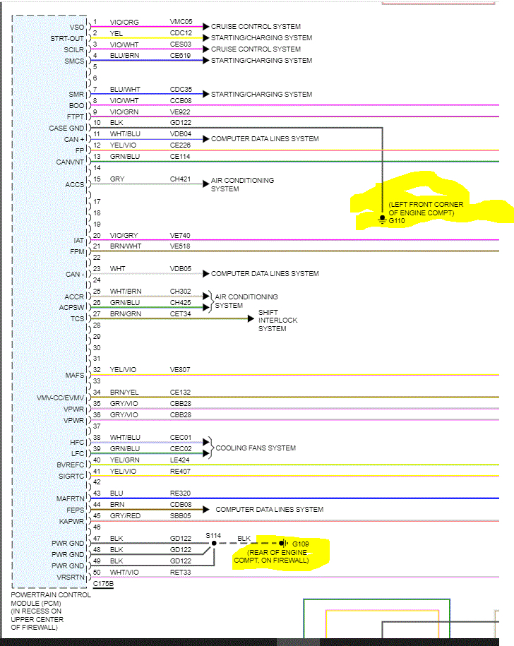
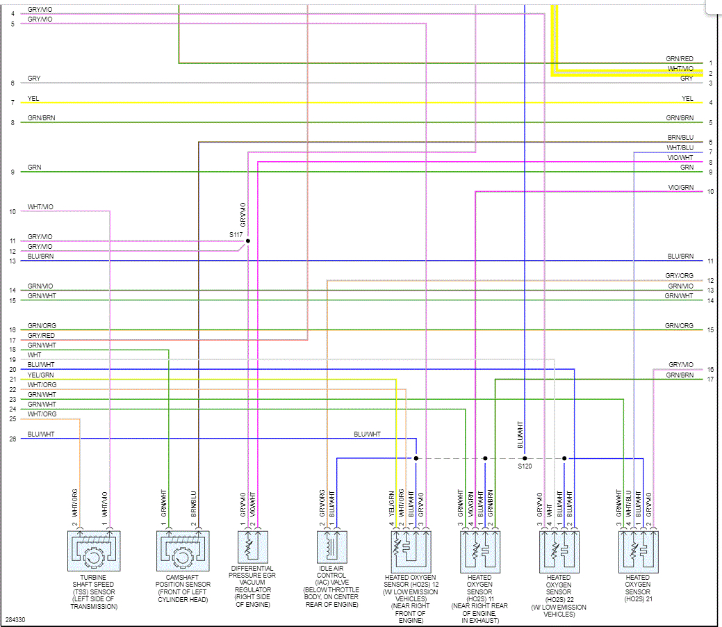
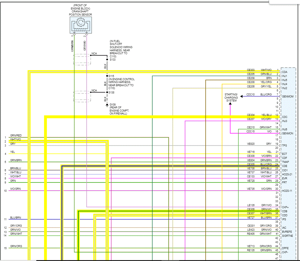
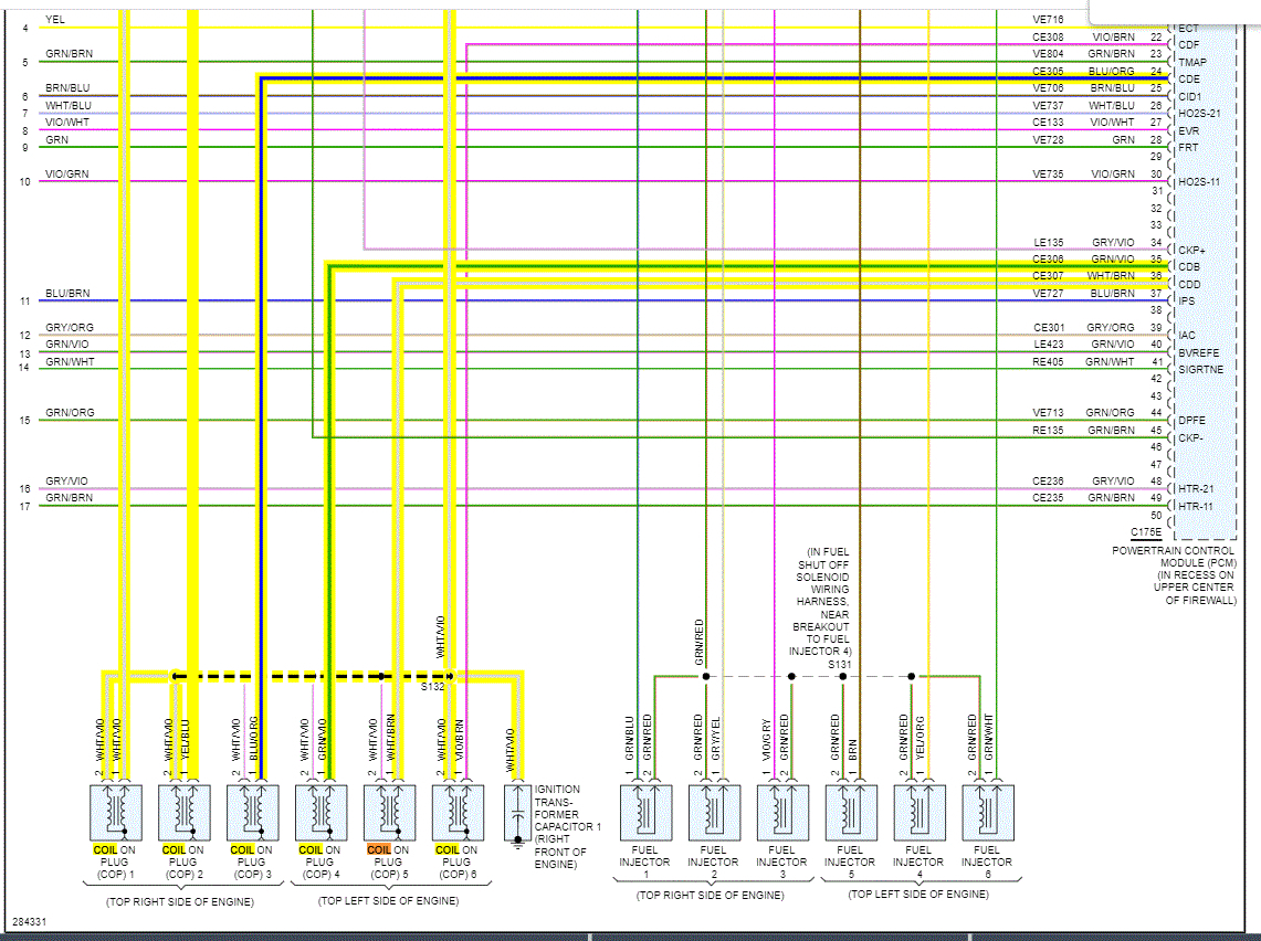
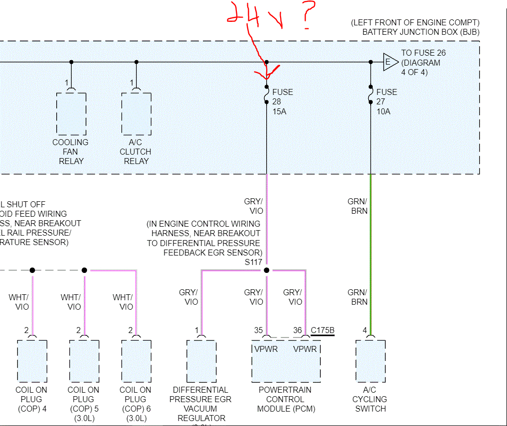
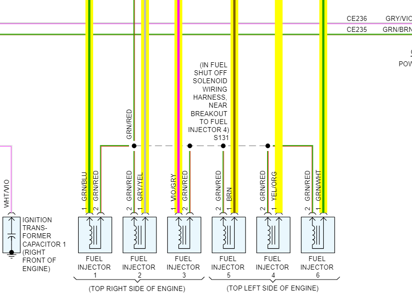
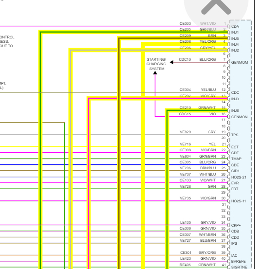
I have battery voltage (+) on the white/violet wire at the cops, but I don't get a ground signal from the PCM at the other wire. Checked Crankshaft position sensor with ohm meter, reads 265 ohms. The car ran fine before I replaced front body parts- driver's side fender, radiator support, bumper cover and grille. Wiring appears to be good.
Friday, January 28th, 2022 AT 12:27 AM

21 Replies

Tiny
JACOBANDNICKOLAS
  • MECHANIC
  • 108,244 POSTS
Hi,

The power is constant to the coils. The ground path is provided via the PCM. When you checked for ground, did you have someone cranking the engine?

Also, if you have a live data scan tool, check for an RPM signal when cranking. If you have one, the CKP is good.

Next, since you did work on the body, I need you to check PCM grounds. I attached a pic below showing two locations to check.

Let me know what you find.

Joe

See pics below.
Was this
answer
helpful?
Yes
No
Friday, January 28th, 2022 AT 8:24 PM
Tiny
BAD HORSE RUNNING
  • MEMBER
  • 11 POSTS
Thanks, done for the week, let you know what I find out.
Was this
answer
helpful?
Yes
No
Saturday, January 29th, 2022 AT 1:15 AM
Tiny
JACOBANDNICKOLAS
  • MECHANIC
  • 108,244 POSTS
Hi,

Sounds good. I will watch for your reply. Hopefully, it is a simple ground issue.

Take care,

Joe
Was this
answer
helpful?
Yes
No
Saturday, January 29th, 2022 AT 12:59 PM
Tiny
BAD HORSE RUNNING
  • MEMBER
  • 11 POSTS
Checked for ground at the PCM plug in, pin 10, it is grounded. Not sure where, but it lights up the test light. There are three wires that ground to the left side inner fender well, that I reconnected when I did the repair, but they are much bigger gauge. Took air box and tube off, no other wire anywhere. The grounds are hooked up on the firewall, didn't touch them. Crankshaft shows working on RPM live feed. Code reader says the fuel injectors are not working, but I assume they don't without spark. The only other thing I can think of that I may have changed; is I think I used the crash sensor that was on the radiator support from the salvage yard. Puzzled as to what happened.
Was this
answer
helpful?
Yes
No
Sunday, January 30th, 2022 AT 10:38 PM
Tiny
JACOBANDNICKOLAS
  • MECHANIC
  • 108,244 POSTS
Have you checked the inertia switch? That would shut down fuel. See pic 1 for location. There is a reset on it. If you haven't already, try to reset it to see if that changes things.

Sorry about the pic. It's a bit cluttered. However, it gives the location.

Let me know what you find. From the accident, the switch may have been triggered (or nearly) and working on it may have caused it to shut down.

It's a theory, but an easy one to check.

Let me know.

Joe

See pic below.
Was this
answer
helpful?
Yes
No
Monday, January 31st, 2022 AT 4:56 PM
Tiny
BAD HORSE RUNNING
  • MEMBER
  • 11 POSTS
Yeah, that's one of the first things I checked. I had also changed the ignition switch due to the u-joint getting bad in the old one. But I put the old one back in after I discovered that I had no spark. I had to change the bottom cover on the power distribution box but couldn't see any wires that may have been damaged doing that. I still have a few hairs left, but it's being a difficult one.
Was this
answer
helpful?
Yes
No
Monday, January 31st, 2022 AT 7:34 PM
Tiny
JACOBANDNICKOLAS
  • MECHANIC
  • 108,244 POSTS
Hi,

We have to be missing something really simple. If you are getting power to the coils, then either the connection between the coils and PCM ground is bad (all of them) or the PCM is bad. The CKP works, correct?

Have you removed the connector for the PCM to inspect the connector pins? Have you checked the pins for a ground signal while cranking?

Take a look below. I attached the schematic between the PCM and the coils. Recheck the connection at the PCM. Check at the PCM for a ground signal.

Let me know.

Joe

See pics below.
Was this
answer
helpful?
Yes
No
Tuesday, February 1st, 2022 AT 2:59 PM
Tiny
BAD HORSE RUNNING
  • MEMBER
  • 11 POSTS
Okay, I have a reading on the scanner (live data) of between 142 - 150 for rpm while cranking, so crankshaft position sensor is working. WHT/VIO from Battery Junction Box to PCM is good, (battery +) WHT/VIO from PCM to ignition coils is good, also WHT/VIO to ignition transformer capacitor is good. I checked WHT/BRN from coil #5 to PCM and it is good, but still no ground signal coming from PCM to coil, or any of the coils. Rechecked grounds at PCM, good. Checking fuse #28 with test light, I have positive voltage at both terminals with the fuse removed. Light is somewhat dimmer at the GRY/VIO side, but not very much dimmer. After moving BJB around checking wires, I lost the ground signal for the Starter Relay, and Scanner wasn't able to link up. I pulled sharply upward on the BJB and the ground signal for Starter Relay returned, and Scanner was able to link up again. So, I seem to have an issue with wires or connections at the BJB, not sure which ones yet, but yellow to PCM, (ground for Starter Relay) a place to start. I had to move wires and BJB up out of the way to weld in half of the inner fender but haven't found any evidence of wire damage. Any advice? Keep you posted.
Was this
answer
helpful?
Yes
No
Wednesday, February 2nd, 2022 AT 11:02 AM
Tiny
JACOBANDNICKOLAS
  • MECHANIC
  • 108,244 POSTS
Hi,

It sounds like you are on the right track. If you lift the box and regain ground, the wire may be okay, but a connection could be loose or weak. I know there is a ground that is located near the battery junction box. Actually, there are two, G104 and G105.

Check that to make sure nothing is loose, damaged, corroded.

See pic 1.

Joe
Was this
answer
helpful?
Yes
No
Wednesday, February 2nd, 2022 AT 1:12 PM
Tiny
BAD HORSE RUNNING
  • MEMBER
  • 11 POSTS
Checked the grounds again, and they are clean and tight. Still haven't found any damaged or loose wires, but have some puzzling results from using voltmeter at the l
Battery Junction box. Fuse#28 (PCM) side that is hot when key is on has battery voltage, while the other side (fused), has 24 volts when the fuse is removed. So, I have twice the battery voltage at the GRY/VIO wire with the fuse removed. If I remove fuse #24 (PCM transmission), the voltage drops to 10.6. With all the fuses back in, the voltmeter reads battery voltage at both sides of fuse#28. Why do I have voltage on the fuse side with the fuse removed, and why is it double the battery voltage? And why would pulling fuse#24 drop that voltage to 10.6? That's with fuse #28 still removed, and the voltmeter still on the fused side (GRY/VIO) wire? And better still, how does the voltage drop back to battery voltage on both sides of the fuse when I put it back in? I'm confused!
Was this
answer
helpful?
Yes
No
Wednesday, February 9th, 2022 AT 12:05 PM
Tiny
JACOBANDNICKOLAS
  • MECHANIC
  • 108,244 POSTS
Hi,

With the fuse removed, do you have 24v at the unpowered side? That doesn't even make sense. You would need 2, 12v batteries connected in a series to produce 24v from 12v batteries.

Look at pic 1 from the power distribution schematic. Is that the side you show 24v? If it is, check fuse 27 or 29 to see if the same thing happens.

Let me know what you find.

Joe

See pic below.
Was this
answer
helpful?
Yes
No
Wednesday, February 9th, 2022 AT 4:26 PM
Tiny
BAD HORSE RUNNING
  • MEMBER
  • 11 POSTS
I'm not where the vehicle is right now, but yes, I have 24 volts on the side that should read 0 volts with the fuse removed. I don't understand how there is any voltage there with the fuse removed, much less 24 volts on a 12-volt system. I have checked the other fuses in that group, 24 through 29, and they all have 0 volts with the fuse removed. I've also checked the power feeding into the PCM relay, and that is 12 volts like it should be. However, with the fuse removed, that 12 volts isn't going anywhere. So the 24 volts in the GRY/VIO wire would have to be feedback coming from the PCM, or some kind of weird short in the box or wiring? I haven't been able to trace the wire back to the PCM yet, not sure which of the 3 plugs it goes to. Planning on further investigation tomorrow, Thursday. Everything else on the vehicle appears to work like it belongs, just no ground signal to the coils, and no fuel injectors, which I assume is because the PCM isn't sending them a ground signal either. Battery wasn't installed during any of the welding, and wires were all up and out of the way. Never run into an issue like this before. If there weren't so many wires involved, I would have spliced in a different Battery Junction Box from salvage yard to see if that would solve the problem. I just don't like to splice so many wires though.
Was this
answer
helpful?
Yes
No
Wednesday, February 9th, 2022 AT 6:29 PM
Tiny
JACOBANDNICKOLAS
  • MECHANIC
  • 108,244 POSTS
Hi,

If you have 24-volts, there has to be a capacitor in the PCM causing this. Nothing else makes sense. I have a feeling the PCM itself is bad. Disconnect the PCM and recheck for power. If the problem is resolved, my first suspect is the PCM has shorted internally to a capacitor. There is no other way to get 24-volts out of this system.

Let me know.

Joe
Was this
answer
helpful?
Yes
No
+1
Thursday, February 10th, 2022 AT 3:45 PM
Tiny
BAD HORSE RUNNING
  • MEMBER
  • 11 POSTS
Sorry I haven't posted anything lately, been busy with other vehicles, so I haven't had time to work on this one in a while. Is there any way to test the PCM other than replacing it? Is it possible to get a used one from a salvage yard for testing purposes? I know that on some vehicles you can swap PCMs easily, while others are much more specific. Thanks for your time and support!
Was this
answer
helpful?
Yes
No
Thursday, June 9th, 2022 AT 8:04 AM
Tiny
JACOBANDNICKOLAS
  • MECHANIC
  • 108,244 POSTS
Hi,

No problem. I'm sorry to hear you are still dealing with this issue.

As far as testing, all you can do is check the questionable pins at the PCM to see if they are doing what they should. In this case, you have 24v from a ground. Something seems to have shorted internally in the PCM.

As far as a used one, you could try it: however, chances are there will be issues with key recognition.

I know online, you can get remanufactured PCMs that are plug-and-play somewhat inexpensively. I don't know what you would pay for one at a salvage yard. If the seller would allow you to try it and return it if it doesn't work, that would at least be worth trying.

Let me know.

Joe
Was this
answer
helpful?
Yes
No
Thursday, June 9th, 2022 AT 8:48 PM
Tiny
BAD HORSE RUNNING
  • MEMBER
  • 11 POSTS
Finally, back to working on the Escape. I changed the sensor above the radiator, and now I have spark, but I don't have any fuel. I can hear the fuel pump run, but no fuel from the injectors. Code reader says P0708-FF, P1702-FF, P0201 through PO 0206, and P0458. Looking for a wiring diagram that shows which plug at the PCM has the wiring for the injectors. And any thoughts on what is wrong.
Was this
answer
helpful?
Yes
No
Monday, July 17th, 2023 AT 9:30 PM
Tiny
JACOBANDNICKOLAS
  • MECHANIC
  • 108,244 POSTS
Hi,

Before we jump to the PCM, at each fuel injector, there will be a green wire with a red tracer. With the key on, see if they have power.

If they don't, check fuse 4 in the battery junction box. In addition to checking the fuse, make sure there is power to and from the fuse.

https://www.2carpros.com/articles/how-to-check-a-car-fuse

Next, if the fuse is good, switch the fuel pump relay with a different one having the same part number.

Let me know what you find,

Also, I attached three pics below. One shows the power supply to the injectors, one shows the injector wiring, and the one is the PCM for each injector. I highlighted the wires related to the injectors.

Let me know if this helps.

Take care,

Joe

See pics below.
Was this
answer
helpful?
Yes
No
Tuesday, July 18th, 2023 AT 8:10 PM
Tiny
BAD HORSE RUNNING
  • MEMBER
  • 11 POSTS
I'm having trouble tracing the +power wire, GRN/red from the relay to the PCM, and the PCM to injectors. Haven't figured out which wire it is at the PCM. Only noticed one GRN/red wire at the PCM, and it is "live" at all times, even with the relay out. So that's not the right wire. Can't access the wires on the injectors without pulling intake manifold, so trying to find them in the wiring harness. But not having much luck. Can you tell me where I can access them in the harness? Thanks for all your help!
Was this
answer
helpful?
Yes
No
Sunday, July 23rd, 2023 AT 9:59 PM
Tiny
JACOBANDNICKOLAS
  • MECHANIC
  • 108,244 POSTS
Hi,

The green/red wire goes from the relay to the injectors. The other wire at the injector is what goes to the PCM. The PCM provides a ground path only for the injectors.

Also, are you checking for power at the green/red wire with the key on? Is it the fuel pump relay you removed? If it is, does the wire have power if you remove fuse 4 shown in the pic above?

Let me know.

Joe
Was this
answer
helpful?
Yes
No
Monday, July 24th, 2023 AT 8:27 PM
Tiny
BAD HORSE RUNNING
  • MEMBER
  • 11 POSTS
Okay, I will need to do some further research, I was thinking that one of the GRN/red wires from the fuel pump relay went to the PCM for the injectors, while the other one went to the fuel pump. But from the sounds of your reply, one wire goes directly to the injectors, while the other one goes to the fuel pump. I definitely have power at the fuel pump, as I can clearly hear it running when I turn the key on, and it doesn't run with the relay removed. Have to check both those wires at the relay end and go from there. Thanks again!
Was this
answer
helpful?
Yes
No
Monday, July 24th, 2023 AT 10:13 PM

Please login or register to post a reply.

Sponsored links