Cranks but will not start scanner won't read?

Tiny
J.STIEG
  • MEMBER
  • 361 POSTS
The ground pins had continuity to ground.
Was this
answer
helpful?
Yes
No
Monday, September 8th, 2025 AT 2:52 PM
Tiny
AL514
  • MECHANIC
  • 5,499 POSTS
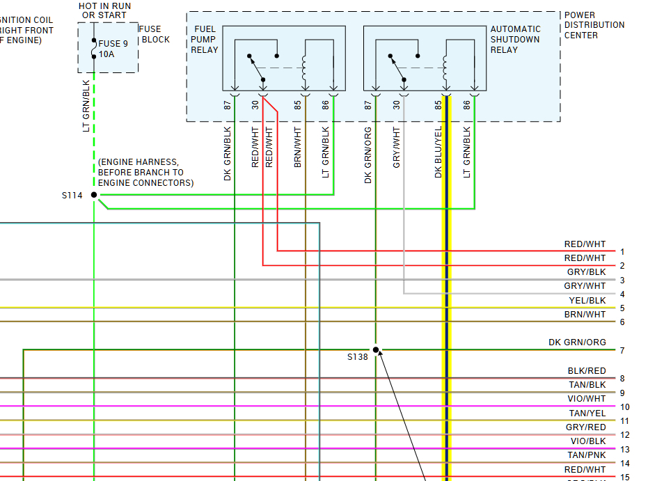
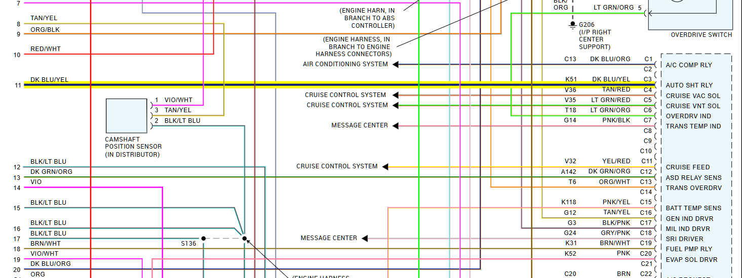
What about the ASD relay control wire to the PCM, with the relay out do you have continuity to PCM connector C pin C3? Thats the wire the PCM should ground to activate the relay. And as for load testing powers and grounds, I always use a higher amperage bulb to make sure that wire can carry enough current. So for example, if there is a wire that is broken some where but there is still one strand of wire that is not broken, the wire will not carry current, but will test fine with a resistance test. Hence the reason for load testing.
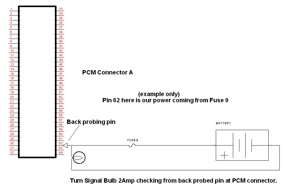
So you would back probe the PCM connector that has the power wire you want to check, in this case A2 and use the back probe to power the test light. And in the case of a Ground wire, you would hook the test light to B+ and use the back probed PCM pin (which goes directly to ground) to ground the test light.
But you want to remember not to pull high amperage through the PCM, only using the wires that come directly from a fuse or relay, and wires that go directly to ground. If you need more info on this. I think I have some diagrams to help.
Was this
answer
helpful?
Yes
No
Monday, September 8th, 2025 AT 3:02 PM
Tiny
AL514
  • MECHANIC
  • 5,499 POSTS
Heres my load testing diagram, excuse my terrible artwork.
Was this
answer
helpful?
Yes
No
Monday, September 8th, 2025 AT 3:21 PM
Tiny
AL514
  • MECHANIC
  • 5,499 POSTS
If you need some time to test, we can come back to this tomorrow. I will get a notification of any messages you post.
One last thing to check is the pin tension inside the PCM connectors. A loose pin not making good contact may look ok, but not have enough tension on the PCM pins.
To check this, I use a pin that is a little smaller than the pins in the PCM, that way I am sure there is good tension inside the female pins of the PCM's harness connector.
Pin tension can be a tricky diag, but over time with connectors being unplugged and also with the pins heating up and cooling down due to normal operation, the pins can spread and prevent good contact. Very important to check and highly over looked many times.
Was this
answer
helpful?
Yes
No
Monday, September 8th, 2025 AT 3:28 PM
Tiny
AL514
  • MECHANIC
  • 5,499 POSTS
Something else to note. With the key On, you should read 12volts on the ASD relay control wire at the PCM connector C pin C3, you should read 12volts on the control wire until the PCM actually grounds the relay, then the voltage will drop to zero. This is another testing method. It can be done with any actuator that is ground side controlled, such as a fuel injector. Just something you can try. The wire is a DarkBlue/Yellow wire. The PCM should turn on the ASD for 2 seconds the same as the Fuel pump relay prime, and then will require a crank signal to reactivate the ASD and fuel pump relays.

If all else fails, when you have done all the testing you can, we can try grounding the ASD relay and see if the PCM comes to life, but this is the last thing to do because we need to be very careful grounding PCM circuits.
Was this
answer
helpful?
Yes
No
Monday, September 8th, 2025 AT 4:20 PM
Tiny
J.STIEG
  • MEMBER
  • 361 POSTS
I got the 5 v reference signal back by changing the PCM, Truck runs good.
Was this
answer
helpful?
Yes
No
Saturday, September 20th, 2025 AT 8:16 PM
Tiny
AL514
  • MECHANIC
  • 5,499 POSTS
Ok glad you got it figured out. I am curious why the voltage regulator failed in the PCM, kind of an odd fault. Would be interesting to take a look at the PCM. But its good its up and running.
Was this
answer
helpful?
Yes
No
Sunday, September 21st, 2025 AT 9:15 AM

Please login or register to post a reply.