Cooling fans dont shut off

Tiny
CARADIODOC
  • MECHANIC
  • 33,752 POSTS
The radiator fan is being turned on by the Engine Computer because it is not getting a valid reading from the coolant temperature sensor. That is a default action in case the engine is running too hot. This can't get any simpler. You already did the tests that showed there has to be a break in the circuit near that sensor, or, much less-likely, the sensor is defective.

If the sensor is buried and it's too difficult to get to, get a used one from the salvage yard, or buy a new one, then plug that into your car's harness. That way you can easily get to the connector to back-probe the wires and take the readings.
Was this
answer
helpful?
Yes
No
Thursday, February 6th, 2020 AT 9:17 AM
Tiny
THISAUTOROOKIE
  • MEMBER
  • 20 POSTS
I do have a spare ECT sensor, and have tried connecting the harness to ECT sensor outside the engine with the tip inserted in hot water, still the dash temp gauge didn't move. It does give me a reading on my scanner, but, no reading on the dash.
But, i would like to back up a little bit, because, i think i might've gave you wrong info to work with from the premise of my post/complaint and i would like to make a correction. I had to take some time to educate myself before writing any more posts.
I never really understood the concept of 5v reference or what they were used for and where/what location it was acceptable to find it at. When you asked if i got 5v with the ECT harness/connector plugged in or unplugged and i said both ways, that was wrong!. I got the 5v reference at the yellow wire pin with the ECT sensor connector unplugged. And when plugged in and (yellow wire) back-probed i got 2.56xx volts. This would seem about the correct voltage i should expect to see right?

A little YouTube video of what happens exactly before it sets off the 284*f and fans kick on. Something interesting happens at 0:28 mark it flashes the 284*f first before going solid.
Https://youtu.be/1pjlqxiqj_0 not that it matters, but, leads me to believe that its PCM issue related.
I think it spits out the voltage reading in 2 stages, because at 1st the voltage dropped to about 1v, then something happens it goes back up to about 3v then starts dropping again, i think its at this point that it fails to maintain its expected proper reading and then fails (or goes into the fail-safe mode), i know this because i tried the same monitor on my Pontiac Bonneville with the same engine and basically the same setup and the same thing happened, the voltage dropped to about 1v, something happens usually happens i feel the engine rpm change then the voltage went up to about 3v and started dropping again from there. But the Bonneville does not have any issue, i was just comparing to see what i should expect to happen. But, its during that 2nd voltage adjustment stage that the impala normally fails as you can see in the YouTube video.

Also, after reading through the posts again from what you said about another resistor living inside the PCM (at pin 26 - if i understand it correctly), that leads me to suspect that that resistor might be bad?? It must be the reason why i get 284*f after the engine reaches 100*f. Perhaps that resistor or its circuitry is bad or maybe the wire is corroded?
Since i got a little better understanding, to i plan to pull out the PCM again and check that pin 26. The yellow signal wire goes to the PCM at that pin 26 correct? That's also where the resistor is PCM is supposed to be living correct?

Hope i make a little better sense now...
Was this
answer
helpful?
Yes
No
Wednesday, February 12th, 2020 AT 1:10 AM
Tiny
SCGRANTURISMO
  • MECHANIC
  • 4,897 POSTS
Hello,

In the diagrams down below I have included a list of expected Ohm's of resistance that your ECT should have at varying coolant temperatures. This is another way to check to see if your vehicle's ECT is working or not. Please put your Digital Multi-meter[DMM] in Ohms Mode. It's the setting with the Omega symbol on it.

Thanks,
Alex
2CarPros
Was this
answer
helpful?
Yes
No
Saturday, February 15th, 2020 AT 4:59 PM
Tiny
CARADIODOC
  • MECHANIC
  • 33,752 POSTS
I put together my own worksheets to walk my students through the operation of these sensors. During that shop class, I insisted they write down the exact voltages for the coolant temperature sensors as the engines warmed up. To their surprise, what they found is exactly what you just described, and that is correct and normal operation.

If we switch for a minute to the throttle position sensor, it has a long resistor element inside it. If you look at it as two resistors tied together, the junction is the point where the movable contact is along that element. The ratio of those two resistor values changes as the contact moves along it, but the total of those two resistors remains constant.

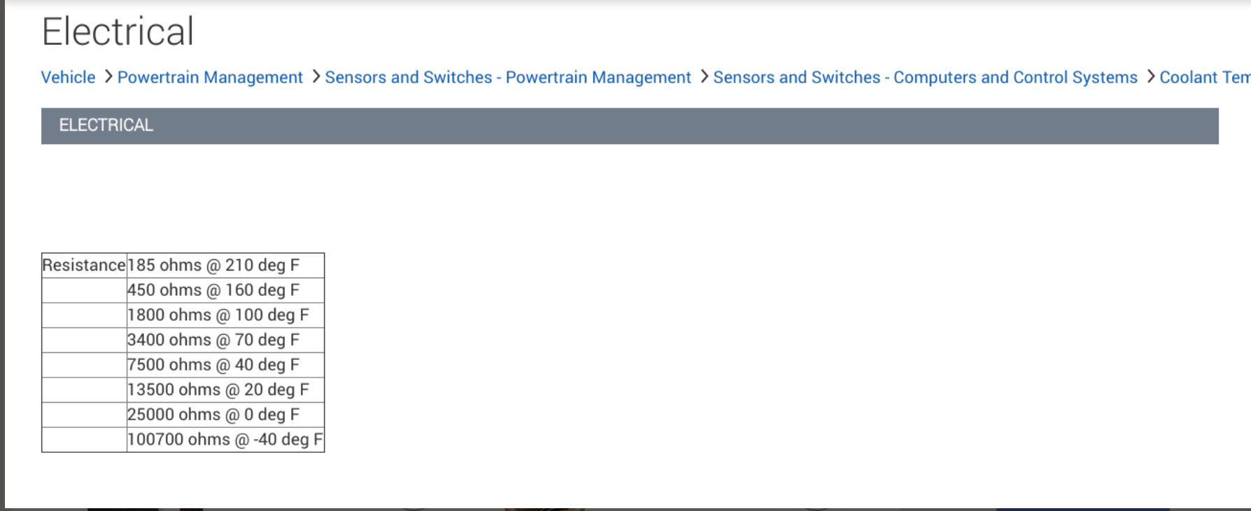
The TPS relies on a mechanical change to effect a change in the signal voltage. The same thing happens with the coolant temperature sensor, except it relies on a chemical change within the resistor in the sensor. On the TPS, it gets 5.0 volts and ground supplied to it, and the signal wire comes off between them. The CTS is the same circuit, except the 5.0 volts is supplied to that circuit inside the computer. Only the ground and signal wires are found at the sensor. As the TPS can be thought of as two resistors, the same is true of the CTS. One resistor is inside the sensor. It changes value with changes in temperature. The second resistor is inside the computer. We'll call that the "dropping" resistor.

As coolant temperature rises, the resistance in the sensor drops. With less total resistance in the circuit, current increases, so more of the 5.0 volts is dropped across that dropping resistor inside the computer. With more of that 5.0 volts used up, what you see on the signal wire goes down. Normal operation is to see roughly 4.0 - 4.5 volts on the signal wire with a really cold engine, then it slowly drops to around 1.5 - 2.5 volts by the time the engine gets to perhaps 120 to 160 degrees.

Here's where you and my students think the problem occurs. Suddenly the voltage jumps back up to around 3.5 volts, then gradually drops again as the engine continues to get up to normal temperature. What has happened is the computer needs to have more accuracy near normal temperature. It gets that by switching in a different dropping resistor.

With a cold engine, the temperature range might go from -39 degrees to around 160 degrees, and the CTS signal voltage drops maybe 2.5 volts. It takes a real big temperature change to make the signal voltage change just a tenth of a volt. With the new dropping resistor switched into the circuit, now that 2.5 volt change covers a much smaller temperature range, from roughly 160 degrees to around 230 degrees. That's a 70 degree range compared to a 200 degree range with the cold engine. That is how the computer gets more accuracy during normal operation.

I've never included this description before because it just adds to the confusion, but the tests you did confirms the circuit is working. You should find the radiator fan does not get turned on when you have those normal readings. It's starting to sound to me like you have an intermittent connection in the sensor's connector, or there's an intermittent break in one of its wires. The common test involves unplugging the CTS with the ignition switch on. As a default in case the engine is running too hot, the computer turns the fan on as a precaution.
Was this
answer
helpful?
Yes
No
Saturday, February 15th, 2020 AT 6:12 PM

Please login or register to post a reply.

Sponsored links