Cooling fans dont shut off

Tiny
THISAUTOROOKIE
  • MEMBER
  • 2005 CHEVROLET IMPALA
  • 3.8L
  • V6
  • 2WD
  • AUTOMATIC
  • 120,000 MILES
Hi, I have a issue that has got me stuck. . I'm having ground sent to the bottom left pin socket (that is 85 I believe) On My Cooling fan #1 relay while engine is running and again For about 2 minutes after ignition is turned off with DTC Code P0117. I have tested my coolant temperature sensor, It's functioning fine, I have 5V reference at the connector. I have also replaced the coolant temperature sensor, that didn't work/solve it. I have checked replaced My MAP sensor and MAF, basically everything tied to the temperature gauge and ECT, but didn't solve the issue. It's causing the cooling fans to come on at those times... Is it the PCM or something else sending ground to the bottom right pin socket (I think that it's Pin 85, correct mMe if I'm wrong) on cooling fan #1 relay? I don't know what is causing it, or how to test/diagnose further to find out where the short is coming from.. Can someone please help?
Thanks.

https://youtu.be/Kml_ODJKVIU
Tuesday, January 14th, 2020 AT 5:04 PM

24 Replies

Tiny
CARADIODOC
  • MECHANIC
  • 33,752 POSTS
P0117 - Engine Coolant Temperature Circuit Low Input

Five volts is not a correct value. That will trigger the radiator fan relay and set a fault code for CTS voltage too high. I have a feeling you inadvertently set code 117 during the diagnosis because it disagrees with that 5.0 volts. Did you unplug the sensor to get that reading or did you back-probe through the connector next to the wire?

Does your relay look like the left one in the second drawing?
Was this
answer
helpful?
Yes
No
+1
Tuesday, January 14th, 2020 AT 5:35 PM
Tiny
THISAUTOROOKIE
  • MEMBER
  • 20 POSTS
No, it does not look like that, that's a 5 pin relay. The relay in question is a 4 pin relay. It looks like the pic below, it is the actual relay in the car.
There is a 5 relay that looks like that, but it's the middle relay, that relay has no problem.
Oh and the p0117 code was already there before I started working on the car. It came on when I noticed the fan running all the time. From my understanding the 5v is supposed to be there. I checked it both by back-probing with the harness plugged in and unplugged, still got 5v.
Was this
answer
helpful?
Yes
No
Tuesday, January 14th, 2020 AT 6:12 PM
Tiny
CARADIODOC
  • MECHANIC
  • 33,752 POSTS
Definitely not supposed to have 5.0 volts. What you might have read is that circuit is indeed fed with 5.0 volts, as are most engine sensors, but with any two-wire temperature sensors, part of the circuitry is tucked away inside the Engine Computer. If you understand electrical theory, this will make sense, otherwise I apologize for making this sound complicated.

This is one big series circuit. It starts at the 5.0-volt supply inside the computer, goes through an internal "dropping" resistor, then it comes out on terminal 26 and goes to the sensor, which is another resistor, but this one is temperature-variable. From there it goes back to the computer on the ground return wire on terminal 13, along with some other sensor grounds, through some internal monitoring circuitry, then to ground after that.

The ground monitoring circuitry is pretty much irrelevant to this story, but explains why that ground wire doesn't just go to ground right on the engine.

That internal resistor is shown above terminal 26. The entire 5.0 volts has to be used up across those two resistors, the one in the computer and the one inside the sensor. As temperature rises, the resistance of the "thermistor" in the sensor goes down, so less and less of that 5.0 volts is dropped across it. There's another chapter to that story too, but there's no need to involve that here. As less of the 5.0 volts is dropped across the sensor, more is dropped across the internal resistor. Those two voltages will always add up to exactly 5.0 volts.

It's when there's a break in the circuit on either wire that current flow through the circuit stops. With no current flow through a resistor, there is no voltage dropped across it. Since we started in the computer with 5.0 volts, and nothing is dropped, or used up, across the internal resistor, we end up with the entire 5.0 volts right at terminal 26 and that yellow wire. That's the voltage that would be displayed on a scanner, and it is what the computer sees and bases its decisions on.

The only way possible to have 5.0 volts on the yellow wire is when there's a break in the circuit. We'd find 5.0 volts before that break and 0 volts after it. (Actually 0.2 volts). This is where even experienced mechanics make the fatal mistake of unplugging the sensor's connector so they can touch the voltmeter's probe to the terminal to take the reading. That just created the break in the circuit, then they're stumped when they find the full 5.0 volts there. Other types of sensors have their own strategies for putting the full 5.0 volts on their signal wires when they're unplugged. There has to be a way to force a bad condition so it will be detected and the appropriate fault code can be set.

Every sensor voltage has to be taken by back-probing through the back of the connector body alongside the wire, while it is plugged in. Any other condition is not valid.

The normal range of sensor voltages is from 0.5 to 4.5 volts. That's for training purposes. In actual practice, you might find one as low as 0.42 volts or as high as only 4.3 volts, but the important point is it can never reach 0.0 or 5.0 volts as those are the two that trigger the fault codes. Throttle position sensors do this with mechanical stops inside them that limit their range of signal voltage from idle to wide-open-throttle. Here again, the signal voltage can only go outside that 0.5 to 4.5 volt range if it is unplugged, or if there's a break in the circuit to include the physical connecting joints inside the sensor.

When you still find 5.0 volts on the yellow wire for the coolant temperature sensor, and while it is plugged in, there has to be a break after that point. By far the most common cause is a stretched terminal in the connector. Those are usually too mall to fit a small pick in there to squeeze them tighter. Instead, there's a colored locking wedge that has to be pried out on the exposed terminal end, then a plastic finger can be pried up to allow the terminal to be pulled out by the wire. Now you can squeeze the terminal a little so it will make a more solid contact. If that doesn't work or if the terminals are corroded, you can order a new connector from any auto parts store, or you can snip one off a similar car in the salvage yard.

Sensor ground wires don't seem to cause as much trouble, and in this case the coolant temperature sensor and the MAP sensor share a common ground. The CTS ground wire could have a break up to the splice, but anywhere after that, it would affect the MAP sensor too.

Your relay is the common GM relay. It threw me for a loop that it uses the same terminal designations that are found on Chrysler relays. Those are the ones in the drawing I posted. For now there's no reason to dig into the relay circuit. The Engine Computer is turning the radiator fan relay on because of that defective condition related to the coolant temperature sensor. That is the default condition because with an invalid signal voltage, the computer can't know engine coolant temperature. It runs the fan for safety just in case the engine gets too hot.
Was this
answer
helpful?
Yes
No
Tuesday, January 14th, 2020 AT 7:08 PM
Tiny
THISAUTOROOKIE
  • MEMBER
  • 20 POSTS
Well, i call it 5v, because i felt it was easier. But, it's actually 4.99v, i have never gotten full 5v, it always read 4.99v.
and as far as pinching the ECT connector terminal, i thought about it being compromised so i went and bought a brand new ect terminal connector, but that still didn't change anything. I have a longer video on YouTube that shows the new ECT and the new connector plug that i bought for it. Https://youtu.be/3gm4ajth1yg if you skip to 05:23 you'll see it.
i understand what you meant by back-probing to get correct reading, but, i get the same 4.99v regardless of back-probing or testing directly.
I have checked everything i can visually see for corrosion and everything is pretty clean and corrosion free.
So, from what i understand, i'm not supposed to have more than 0.5v at the coolant temp sensor wire? And so, you're super suggesting further investigating the coolant temp sensor ground wire for breaks and degrading? How far should i go? Where does that wire terminate? I don't think it would be wise to start unwrapping the wire looms just to trace the ECT ground wire. So if you can just tell me where the wire terminates and/or at what points i should do my testing to see where i can possibly find the break at, that would be very helpful.
Was this
answer
helpful?
Yes
No
Tuesday, January 14th, 2020 AT 8:24 PM
Tiny
THISAUTOROOKIE
  • MEMBER
  • 20 POSTS
I just went back out there and tested the ECT sensor at the connector with it plugged in and unplugged, I got battery voltage on both yellow and orange/black wires. I couldn't get the 4.99v that I had. So that can't be good.
Was this
answer
helpful?
Yes
No
Tuesday, January 14th, 2020 AT 10:43 PM
Tiny
THISAUTOROOKIE
  • MEMBER
  • 20 POSTS
Hi, where can I find wiring diagram for the coolant temp sensor and how the wires lead to the PCM? Or rather what is the pin number for the ECT sensor wire(s)? There are 2 blocks of wire in the PCM one on top and the other below, which one has the ECT wire(s)?
I pulled the PCM and figured I should test for continuity on the the coolant temp sensor wire. I have visually inspected all the wires and don't see any apparent damage.
Am I going about it the right way?
Any other way I can do it better?
And any other tests/checks I can do while i'm at it?
Thanks.
Was this
answer
helpful?
Yes
No
Wednesday, January 15th, 2020 AT 1:04 AM
Tiny
THISAUTOROOKIE
  • MEMBER
  • 20 POSTS
Please forgive my stupidity in that 2nd to last message, I was so confused and my head was so full that I was checking the reference voltage and forgot to turn the ignition on.
But, again something really weird happened, after I took apart the PCM to check the wires, I learned something new and wanted to test it out, so I put the PCM back together, after my test I turned off the ignition and was expecting the cooling fans to come on as it used to, to my surprise, it did not, I went and pushed the relays back in to make sure that I didn't leave them out as I did when the fan was coming on, the fans still didn't come on. This is really weird, I even tested for that ground that was feeding the bottom right relay pin causing the fans to kick on and run for 2 minutes after ignition off, not there anymore, this is really freaking me out.
Was this
answer
helpful?
Yes
No
Wednesday, January 15th, 2020 AT 2:10 AM
Tiny
CARADIODOC
  • MECHANIC
  • 33,752 POSTS
The service manuals always include a lot of resistance / continuity tests in their troubleshooting charts, but those have you do a whole bunch of little mind-numbing tests that can be skipped over. It is much for efficient to use the voltage tests to locate the cause of a problem, then you can use resistance tests to verify what you found or to isolate it to a small area.

4.99 volts is in effect, 5.0 volts, and the only way that can be at the sensor is there has to be a break after that point. The next step is to back-probe the black wire on the coolant temperature sensor. That one must have 0.2 volts. If you find 5.0 volts, the break is after that point.

Next, I'm still going on the assumption the MAP sensor is not setting a fault code, so that rules out a problem in the part of the ground wire both sensors share. That means the break has to be between the sensor, (blue arrow), and splice 186, (red arrow).

I just noticed another connector, C126, right below the blue arrow, in that ground circuit. They show it as terminal "A", which could mean it's a single-wire connector, or its the first one of multiple wires in that connector.

The second drawing shows where the two sensors are located. Logic would dictate the part of the ground wire with the break runs between them. The connector will be in that area too.

If you do find 0.2 volts on the CTS black wire, the break has to be between one of those pairs of mating terminals, or the sensor is open. Do a resistance test on the sensor between those two terminals. The exact value is irrelevant but expect to see anywhere from 1,000 ohms to perhaps as much as 30,000 ohms.
Was this
answer
helpful?
Yes
No
Wednesday, January 15th, 2020 AT 4:06 PM
Tiny
THISAUTOROOKIE
  • MEMBER
  • 20 POSTS
Hey, quick update, I put the car back together today and drove it, I noticed the temperature gauge is not working, but my live scanner is reading the coolant temperature is stuck on 140*C (284*F) at cold engine. No wonder it's turning the fans on. Also, DTC p0117 came back.
Was this
answer
helpful?
Yes
No
Wednesday, January 15th, 2020 AT 8:06 PM
Tiny
CARADIODOC
  • MECHANIC
  • 33,752 POSTS
What's the voltage on the black wire at the sensor?
Was this
answer
helpful?
Yes
No
Thursday, January 16th, 2020 AT 12:37 PM
Tiny
THISAUTOROOKIE
  • MEMBER
  • 20 POSTS
There's physically no way to get a hand down where the sensor is to test there. So I test it on top where the harness that connects to the temperature sensor unplugs. (Looks like that's what is labeled as terminal A at C126, that you also mentioned?) If that is the case, then the wire labeling in the wiring diagram must be wrong because as you can see in my picture it's a 2 wire connector.
But, voltage on the black wire with key on is around 15mV.
Was this
answer
helpful?
Yes
No
Friday, January 17th, 2020 AT 2:46 AM
Tiny
THISAUTOROOKIE
  • MEMBER
  • 20 POSTS
And just to give a feedback on your last 2 post. I really do that wiring diagram is wrong, i'm confused looking at it, because from the ECT sensor, the drawing only shows one wire ground going to the MAP and the other end is one wire signal going to the PCM, which leaves me one question, where is the temperature gauge wire? Or rather what wire controls the temperature gauge and where does it go to/come from?
Was this
answer
helpful?
Yes
No
Friday, January 17th, 2020 AT 3:11 AM
Tiny
CARADIODOC
  • MECHANIC
  • 33,752 POSTS
On older models there were two coolant temperature sensors. The sensor for the dash gauge always had just one wire. It was grounded through the engine block. Coolant temperature sensors for the Engine Computer have to be more precise. They also always have two wires. The ground wire goes through the Engine Computer before it gets to ground.

Between the late '90s and mid 2000s, they started using just the two-wire sensor for the Engine Computer. Typically engine sensor data is broadcast out on the data buss wires to all the other computers. The Body Computer uses some of that data, then sends it to the instrument cluster, which is another computer module. That means there's three computers involved in running the dash gauge.

I suspect you're letting the MAP sensor confuse you. That doesn't have anything to do with the coolant temperature sensor except that they share a common ground wire. That's no different than working on a dead tail light that shares a common ground with all the other lights on the car. The only thing the MAP sensor circuit is good for is to verify one small part of that ground circuit has to be okay.

By your voltage readings, the break has to be between the orange and red arrows in the diagram a few replies back. As far as the terminal designations, you'll see a "B" right at the top of the coolant temperature sensor, and an "A" right below it. Those signify there's two wires in that connector. C126 is a different connector, and they show the sensor ground wire as terminal "A", but that doesn't necessarily mean there's just one wire in that one. However, I looked it up, (drawing below), and I was surprised to see it's a two-wire connector. Then, after looking closer at the diagram, I see terminal "B" in C126 is right above the orange arrow. It looks like they added that short pigtail either to create easily-accessible test points, or because there was a change made in the placement of the sensor after the wiring harnesses had been manufactured, and the connector didn't quite reach.

It looks like the connector in your photo is C126.

Regardless, there has to be a break between the orange and red arrows. Starting at the top at terminal "B" in C126, (yellow wire), and working your way down to the splice at the red arrow, if you find 5.0 volts, the break is after that point. If you find 15 mv, the break is before that point. Remember, these voltages are only valid when all the connectors are plugged in and you are back-probing next to the wires. When the meter's probe is too fat to fit in there, I use a stick pin or sewing needle, then touch the probe to that. Also be aware if you get a reading of 0 volts, there's a good chance the probe isn't touching the terminal. I've gone down the wrong path many times from making that mistake.
Was this
answer
helpful?
Yes
No
Friday, January 17th, 2020 AT 3:44 PM
Tiny
THISAUTOROOKIE
  • MEMBER
  • 20 POSTS
"Regardless, there has to be a break between the orange and red arrows. Starting at the top at terminal "b" in c126, (yellow wire), and working your way down to the splice at the red arrow, if you find 5.0 volts, the break is after that point. If you find 15 mv, the break is before that point."
I got what you're saying. But, let me ask 2 quick questions: does this cars not have BCM? And do they not have/play any role in the operation of these cooling systems or temp gauge? Because my temp gauge is not working either and I have no clue/suggestion as to why it's not working. (I was talking to a mechanic in my neighborhood that told me he worked on the exact cooling fan problem i'm having in Buick car with the same engine. And he said he never did figure it out either. And he mentioned something about the BCM having some role in the operation of some of the sensors and gauges)

So you're suggesting that I have a break in the yellow signal wire going back (to the temp gauge? Is that where the yellow signal wire goes to)

Tracing this break in these wires would be a tedious task. So, before I go ripping apart the wire looms in the wiring harness, I just want to know, if there's a break in the wire as you believe, shouldn't that affect the coolant temp reading on the obdii scanner also?
Was this
answer
helpful?
Yes
No
Monday, January 20th, 2020 AT 1:28 PM
Tiny
THISAUTOROOKIE
  • MEMBER
  • 20 POSTS
Please when you get a chance take a look at this video to see if you can understand it better that i do.

Https://youtu.be/b8jhqbx1auq

I get a reading until temperature reaches around 105-110*F then it just to 284*F automatically kicking on the cooling fans.
Was this
answer
helpful?
Yes
No
Monday, January 20th, 2020 AT 1:33 PM
Tiny
CARADIODOC
  • MECHANIC
  • 33,752 POSTS
You're making this way too complicated, although now I'm willing to add the sensor itself to the list of suspects. I made this drawing to show everything that is involved with the coolant temperature sensor. That is everything the Engine Computer uses to know engine temperature. Nothing more; nothing less.

284 degrees is the default reading it goes to when there's an open circuit, meaning a break in the circuit. As I mentioned early on, this is rarely caused by the sensor itself because there's just one resistor inside it, but Ford did have just that problem in the early '90s, and it was real common. It is possible this is what's happening to your sensor too, but it is just as likely there is an intermittent break between a pair of mating connector terminals.

When it goes to 284 degrees is when the signal voltage goes to 5.0 volts. What you might do now is when it does that, stop the engine, then turn the ignition switch back on and watch that reading over the next few minutes. As the engine cools down, if the reading suddenly drops to 110 degrees, and you're not disturbing anything under the hood, it is likely the sensor that is defective. If the same thing happens repeatedly, meaning the signal voltage always pops up from around 110 degrees to open circuit, that would also point to the sensor.

If the signal voltage changes at all different times, especially while you're flexing the wiring harness, that would point more to a connector terminal problem.
Was this
answer
helpful?
Yes
No
Monday, January 20th, 2020 AT 2:49 PM
Tiny
CARADIODOC
  • MECHANIC
  • 33,752 POSTS
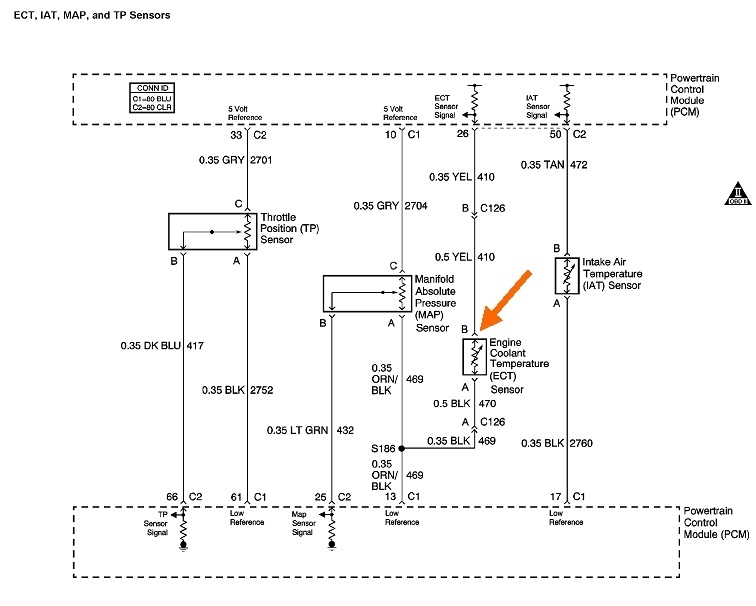
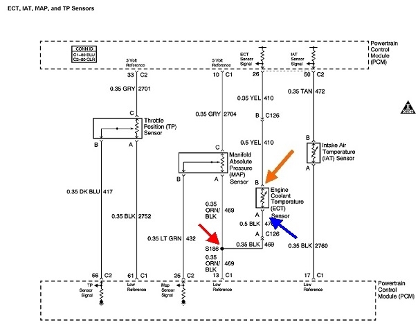
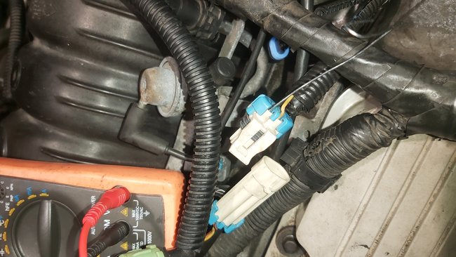
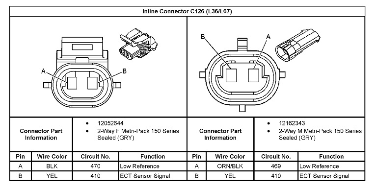
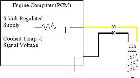
You don't have to tear the entire wiring harness apart. You already measured 5.0 volts, (4.99 volts), at some point along the yellow wire. Everything up to that point has to be okay. Continue working your way toward the sensor to find the first point that 5.0 volts is no longer there. That is when you crossed over the break.

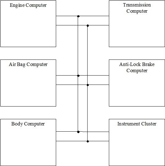
To add to the story of the dash gauge, this drawing is a representation of six of the dozens of computer modules on your car. There is a pair of "data buss" wires connecting all of them. On some car models the data buss is a single wire. When it's a pair of wires, they'll always be twisted around each other, called a "twisted pair". Stray magnetic interference would induce voltages that would confuse the computers. By twisting the wires, that interference affects both wires equally, and the voltages induced cancel each other out.

Some models today use up to three separate data busses. There is so much information being passed along them that it would take too long to share critical or time-sensitive data. An example would be for the air bag system. The deployment of the air bag is timed to milliseconds, and there isn't time to waste until it's time for that computer to send and receive information.

In this story, the Engine Computer knows all the operating parameters of the engine, including load, rpm, fuel volume, throttle direction and rate of change, along with all the data from its sensors. It controls the cruise control servo, so it needs to know when the brake pedal is pressed, when steering wheel switches are pressed, and it needs to know road speed.

The Transmission Computer needs to know engine load and speed, and coolant temperature. It already knows road speed from its dedicated vehicle speed sensor.

All of these computers know a lot of data by themselves, then, rather than having duplicate sensors for each computer, they get some of their needed information from the other computers.

Each computer takes turns broadcasting its information out onto the data buss, then it can be seen by all the other computers. Starting with the Engine Computer, when it is its turn, it sends out sensor data and all engine operating conditions such as rpm, charging system voltage, and which relays and solenoids it has activated. Among that data is coolant temperature.

The Transmission Computer, along with all the others, looks at that data and picks out what it needs and ignores the rest. It needs to see throttle position and engine load along with the road speed it already knows, to calculate shift points. It needs to know coolant temperature to know when it is okay to engage the torque converter's lock-up clutch. It ignores information related to the knock sensor, ignition timing advance, and the number of milliseconds the injectors are being pulsed open.

A few milliseconds later, the Transmission Computer gets its turn at sending out data. It sends road speed, which gear it's in, whether torque converter lock-up has occurred, and data related to the amount of wear on the clutch plates.

Much of that data is ignored, but another computer can be added to the data buss. That is the scanner we use to read this data and to read diagnostic fault codes.

The Body Computer also is able to read all the information on the data buss, but it too just picks out what is needs and ignores the rest. It has its own sensors too to get information that it shares on the data buss. Fuel level is one of those. In this story, the Body Computer picks out the coolant temperature reading from the message it saw from the Engine Computer. It analyzes that digital signal, interprets it, then translates it into a different digital signal. When its turn comes to broadcast its information onto the data buss, most of it is ignored by the other computers, except for the instrument cluster. That is the only one capable of understanding the digital signal related to coolant temperature. Logic would dictate the instrument cluster could take that data right from the Engine Computer's message, but to do that for many dozens of gauges, warning lights, and other functions would make the cluster more complicated than it already is. Since that data is already being processed by the Body Computer, it is sent to the cluster, but in a modified form that will be ignored by the other computers, otherwise they would be getting two different coolant temperature messages from two different sources. The transfer of data from the Body Computer to the instrument cluster is not time-sensitive, meaning it doesn't matter if it shows up right now, or a fraction of a second from now. Compared to engine performance, or the critical timing of air bags and anti-lock brakes, Body Computer data can be sent on a low-level data buss of its own, or it can just wait until its chance to broadcast comes along on the higher-level data buss.

Once a packet of data is transmitted onto the data buss by the Body Computer, the instrument cluster takes that and analyzes it, then turns it into the voltages that run the gauges and warning lights. This is where the coolant temperature gauge responds to what the Engine Computer is seeing from the coolant temperature sensor.

All of this data sharing became more and more involved over the years. On older cars up to around the mid to late '90s, the instrument cluster wasn't such an unnecessarily-complicated computer module. That was when, instead of interpreting digital signals, they just used their own, very reliable circuits and sensors to run the gauges. That was when there was a second coolant temperature sensor just for the dash gauge, and it always had just one wire connected to it. Those gauges were never meant to be particularly accurate. Their main purpose was for the driver to notice when something was out-of-the-ordinary. One coolant temperature gauge could run at half-scale, and another one could run at 3/8, and both engines could be running perfectly.

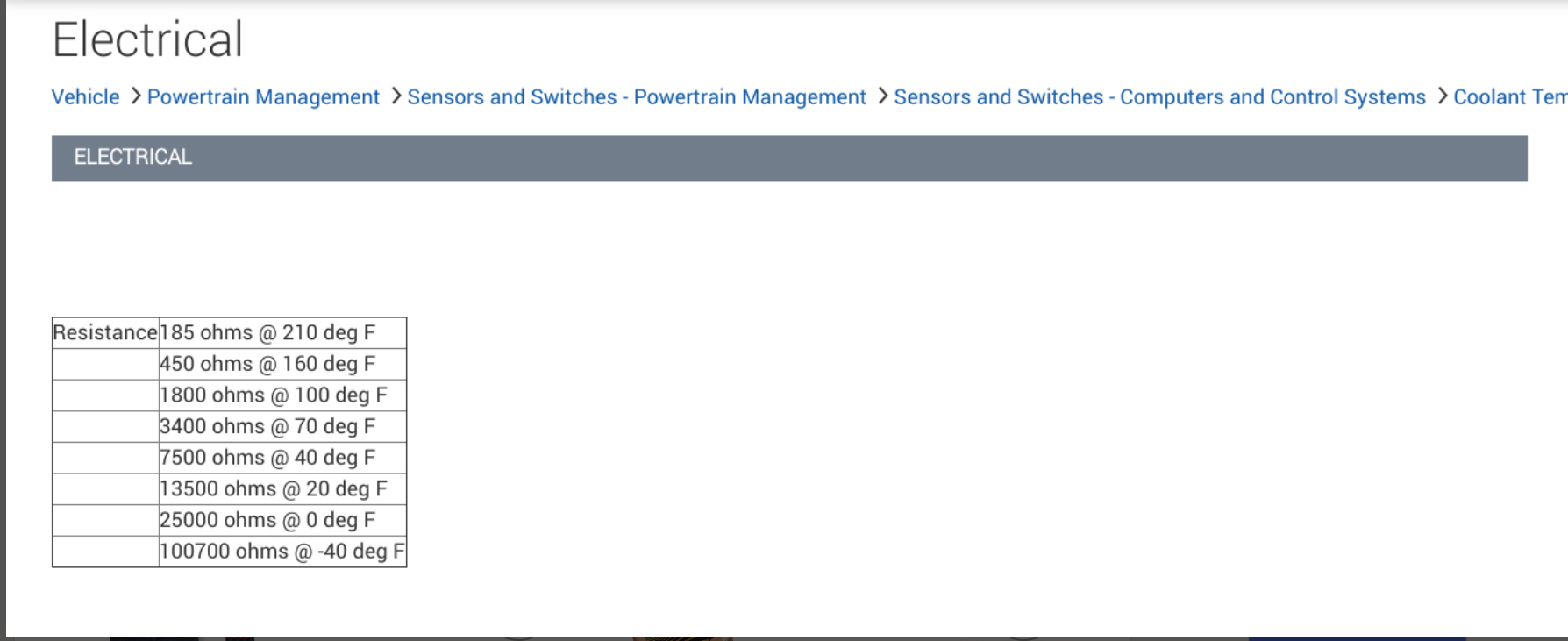
Coolant temperature sensors for Engine Computers have to be very accurate, but with all the computer circuitry involved before the gauge's pointer is placed to the desired position, there are just too many variables to expect the gauge reading to be right on the money. The only way to know the exact coolant temperature, or any other sensor reading, is with the scanner. That takes the information from the data buss exactly as it was transmitted by the computer, and interprets that so we can read it.
Was this
answer
helpful?
Yes
No
Monday, January 20th, 2020 AT 3:54 PM
Tiny
THISAUTOROOKIE
  • MEMBER
  • 20 POSTS
Hey, I was thinking is it possible that my temperature gauge stepper motor is bad? Maybe that's why my temperature gauge isn't showing any reading at all? Also, Is it possible that it has any ties with the cooling fan system/circuit?
Was this
answer
helpful?
Yes
No
Wednesday, February 5th, 2020 AT 2:23 PM
Tiny
CARADIODOC
  • MECHANIC
  • 33,752 POSTS
Pursue the wrong voltage at the coolant temperature sensor. You can't expect the dash gauge to read correctly when the sensor circuit isn't working. GM has had a lot of trouble with their stepper motors that run their gauges, but the positions of the pointers are not monitored. The instrument cluster computer sends varying voltages and polarities to those motors, then it just assumes the pointers moved to their intended positions. If they don't, no computer knows that or responds to that.

The radiator fan being switched on is the second clue. That is also a result of the sensor circuit problem, but it has nothing to do with the dash gauges.
Was this
answer
helpful?
Yes
No
Wednesday, February 5th, 2020 AT 2:53 PM
Tiny
THISAUTOROOKIE
  • MEMBER
  • 20 POSTS
Okay, I am also pursuing the cooling fan issue, armed with all the helpful tips you've provided thus far.
But, I just learned that the gauges does have stepper motors that potentially do go bad. So, I was just asking the question because the dash temperature gauge is out, no kind of output at all being detected, I mean if it was solely a temperature sensor issue, I would expect the temperature gauge (if nothing else is wrong with it) to at least read something, even though it'll be a wrong reading. But, in this case, I don't even get any kind of movement at all. Other people that had this cooling fan issue that I have spoke to said their temperature gauge did show some kind of reading even though it was inaccurate reading.
Was this
answer
helpful?
Yes
No
Wednesday, February 5th, 2020 AT 7:51 PM

Please login or register to post a reply.

Sponsored links