Hi and thanks for using 2CarPros.
There is a chance you are correct. There is a bearing in there too that can go bad. To be sure what is making the noise, you need to take it apart. Make sure to disconnect the battery prior to working around the air bag. First, I am going to provide the directions for replacing the clock spring. Make sure to follow the directions for removing power to the air bag system. The attached pictures correlate with these directions.
______________________________________________________________
PROCEDURES
CLOCKSPRING
Part 1
picture 1
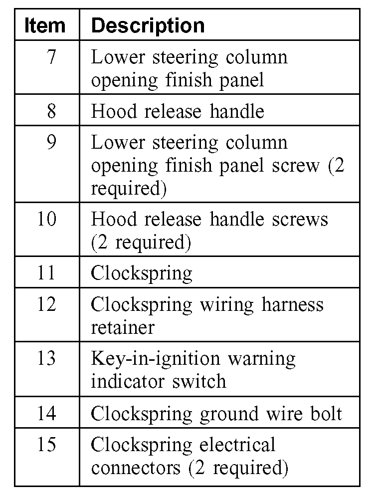
Part 2
picture 2
Removal
WARNING:
- Always wear safety glasses when repairing an air bag supplemental restraint system (SRS) vehicle and when handling an air bag module. This will reduce the risk of injury in the event of an accidental deployment.
- Carry a live air bag module with the air bag and trim cover pointed away from your body. This will reduce the risk of injury in the event of an accidental deployment.
- Do not set a live air bag module down with the trim cover face down. This will reduce the risk of injury in the event of an accidental deployment.
- After deployment, the air bag surface can contain deposits of sodium hydroxide, a product of the gas generant combustion that is irritating to the skin. Wash your hands with soap and water afterwards.
- Never probe the connectors on the air bag module. Doing so can result in air bag deployment, which can result in personal injury.
- Air bag modules with discolored or damaged trim covers must be installed new, not repainted.
- To reduce the risk of personal injury, do not use any memory saver devices.
NOTE:
- The air bag warning lamp illuminates when the restraints control module (RCM) fuse is removed and the ignition switch is ON. This is normal operation and does not indicate a supplemental restraint system (SRS) fault.
- The SRS must be fully operational and free of faults before releasing the vehicle to the customer.
- A repair is made by installing a new part only. If the new part does not correct the condition, install the original part and perform the diagnostic procedure again.
1. Depower the system.
2. Remove the driver air bag module.
3. NOTE: Make sure the wheels are in the straight-ahead position.
Remove the steering wheel.
4. Remove the ignition lock cylinder.
5. Remove the 2 screws and position the hood release handle out of the way.
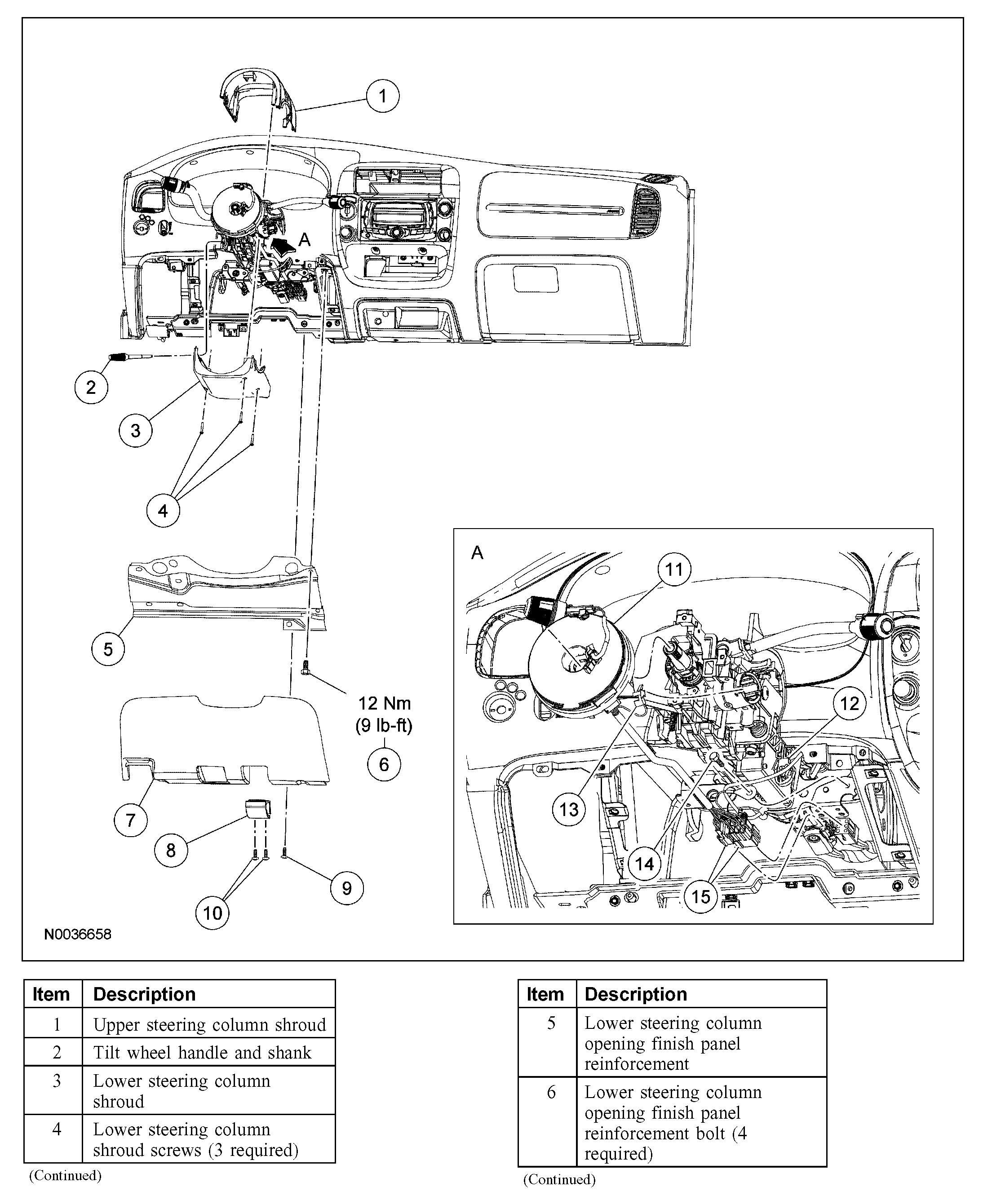
6. Remove the screws from the lower steering column opening finish panel. Then pull out to release the retaining clips and remove the lower steering column opening finish panel.
7. Remove the 4 bolts and remove the lower steering column opening finish panel reinforcement.
8. Remove the tilt wheel handle and shank.
9. Remove the 3 screws and the lower steering column shroud.
10. Position the upper steering column shroud up enough to access the clockspring retaining clips.
11. Detach the clockspring wire harness from the wiring retainer.
picture 3
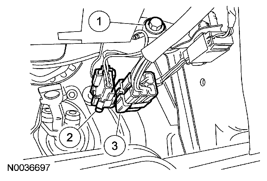
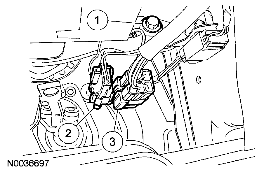
12. Remove the clockspring electrical connectors.
1 Remove the clockspring ground wire bolt.
2 Release the pin-type retainer and disconnect the clockspring electrical connector.
3 Release the pin-type retainer and disconnect the clockspring electrical connector.
picture 4
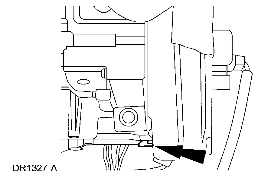
13. Release the lower clockspring retaining clip.
picture 5
14. Remove the clockspring.
1 Detach the key-in-ignition warning indicator switch from the lock cylinder housing.
2 Release the remaining 2 clockspring retaining clips.
3 Remove the clockspring.
Installation
Vehicles receiving a new clockspring
1. NOTE: A new clockspring is supplied in a centralized position and held there with a key.
Remove the key from the clockspring, holding the rotor in its centralized position.
- Do not allow the clockspring rotor to turn.
Vehicles needing clockspring recentering
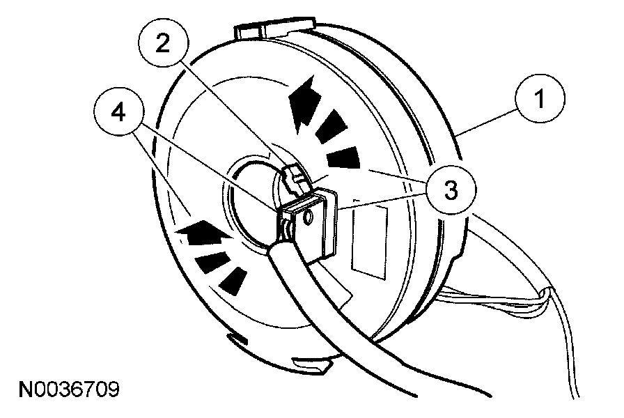
picture 6
2. WARNING: Incorrect centralization may result in premature component failure. If in doubt when centralizing the clockspring, repeat the centralizing procedure. Failure to follow this instruction may result in personal injury.
CAUTION: Make sure the road wheels are in the straight-ahead position.
NOTE: If a clockspring has rotated out of center, follow through with this step.
Centralize the clockspring.
1 Hold the clockspring outer housing stationary.
2 Depress the clockspring locking tab to release the rotor.
3 CAUTION: Overturning will destroy the clockspring. The internal ribbon wire acts as the stop and can be broken from its internal connection.
While holding the clockspring locking tab in the released position, turn the rotor counterclockwise, carefully feeling for the ribbon wire to run out of length and a slight resistance to be felt. Stop turning at this point.
4 While holding the clockspring locking tab in the released position, turn the clockspring clockwise approximately 2.25 turns. This is the center point of the clockspring.
- Release the clockspring locking tab. Do not allow the rotor to turn from this position.
All vehicles
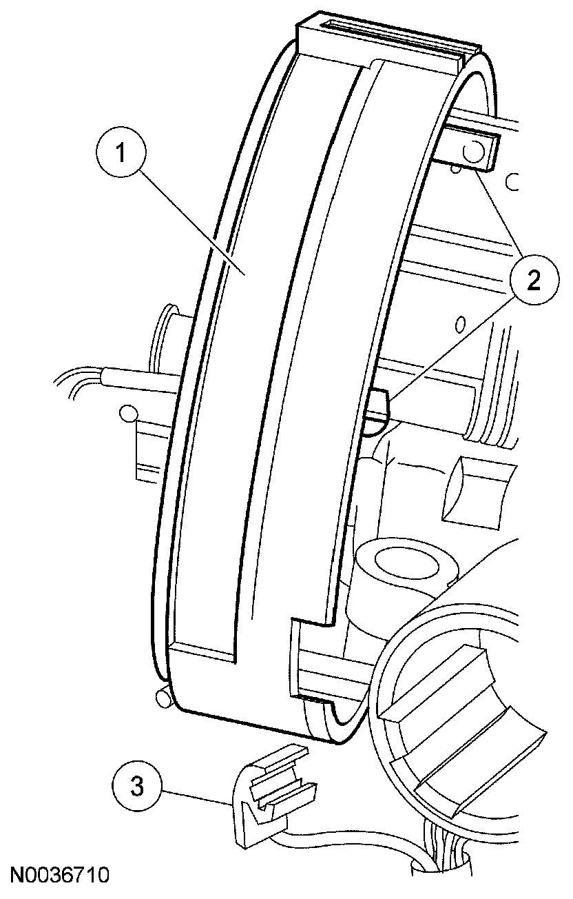
picture 7
3. NOTE: Slight turning of the clockspring rotor is allowable for alignment purposes to the steering column.
Install the clockspring onto the steering column.
1 With the flats of the clockspring aligned to the flats of the steering column, slide the clockspring onto the steering column.
2 Engage the upper and side retaining tabs.
3 Attach the key-in-ignition warning indicator switch to the lock cylinder housing.
picture 8
4. Engage the lower clockspring retaining clip.
picture 9
5. Install the clockspring electrical connectors.
1 Install the bolt.
2 Connect the electrical connector. Install the pin-type retainer and electrical connector to the bracket.
3 Connect the electrical connector. Install the pin-type retainer and electrical connector to the bracket.
6. Attach the clockspring wire harness to the wiring retainer.
7. Reposition the upper steering column shroud.
8. Position the lower steering column shroud and install the 3 screws.
9. Install the tilt wheel handle and shank.
10. Position the steering column opening finish panel reinforcement and install the 4 bolts.
- Tighten to 12 Nm (9 lb-ft).
11. Align the lower steering column opening finish panel and push in, seating the retaining clips. Then install the 2 screws.
12. Position the hood release handle. Install the 2 screws.
13. Install the ignition lock cylinder.
14. NOTE: Make sure the wheels are in the straight-ahead position.
Install the steering wheel.
15. Install the driver air bag module.
16. Repower the system.
_________________________________________________________-
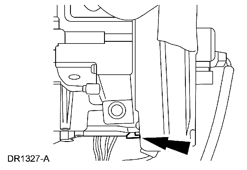
picture 10 shows location of the air bag module.
________________________________________________________
Here are the directions for removing the steering wheel. The remaining pictures correlate with these directions.
Steering Wheel
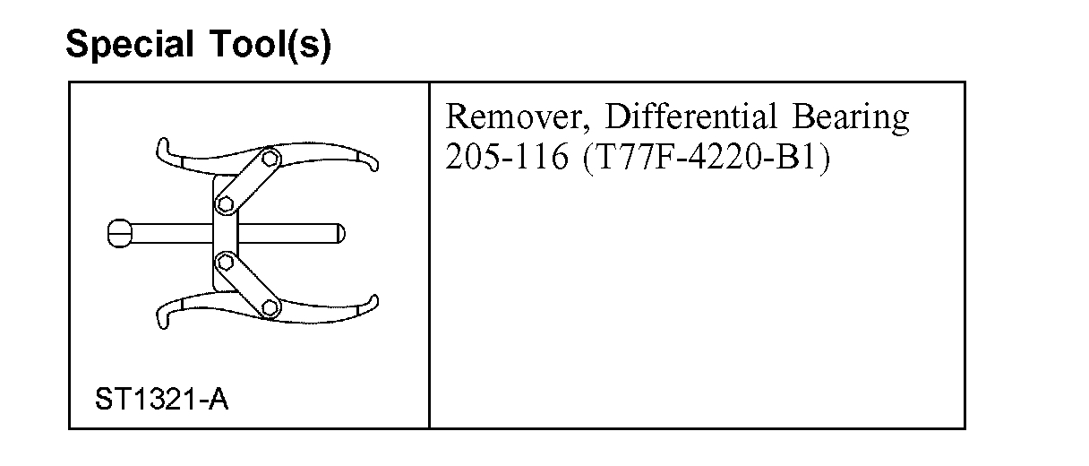
Special Tool(s)
picture 11
picture 12
Removal and Installation
1. Turn the steering wheel to the straight-ahead position and turn the ignition switch to the OFF position.
2. Remove the driver air bag module.
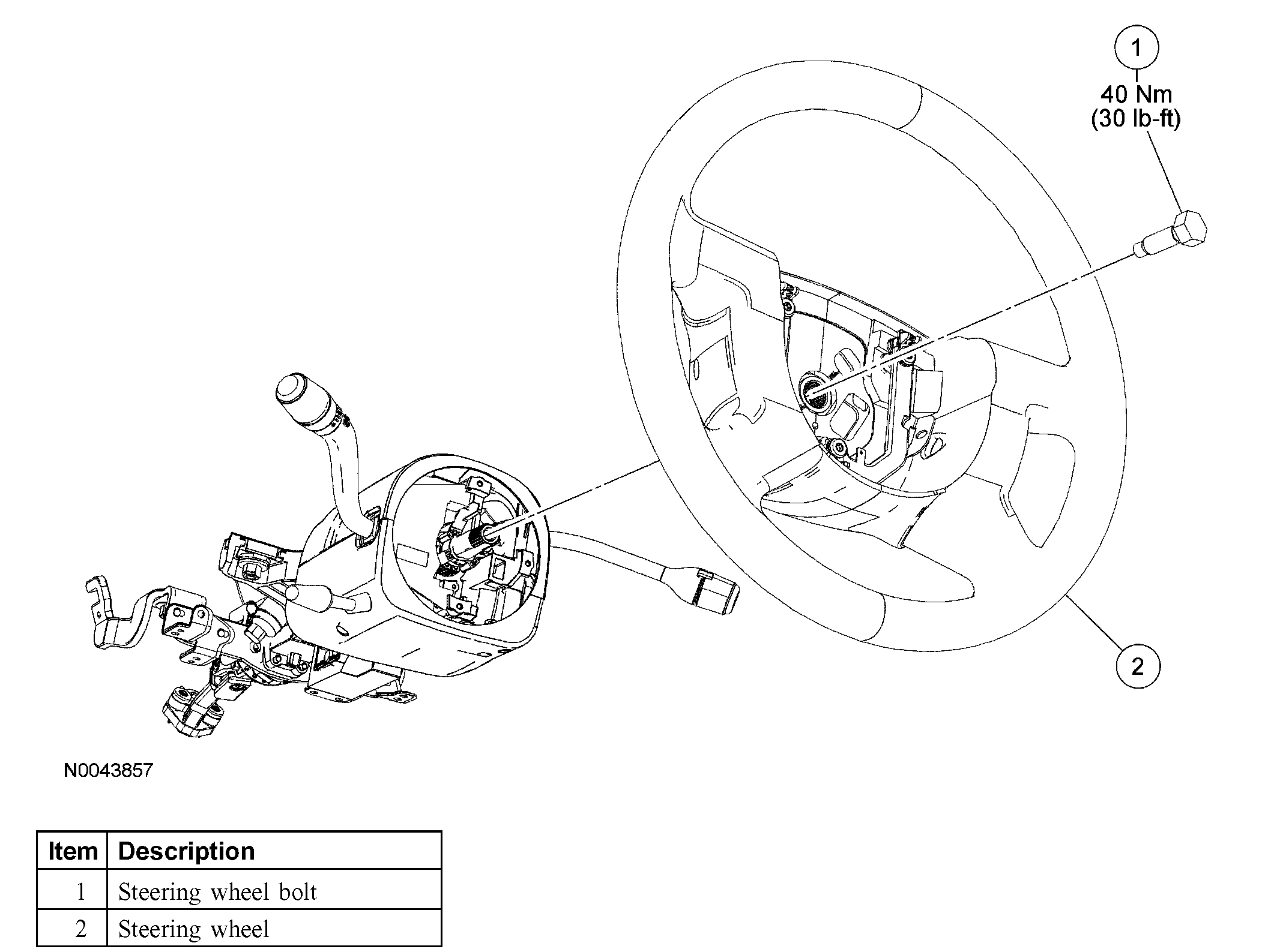
3. Loosen the steering wheel bolt.
^ To install, tighten to 40 Nm (30 ft. lbs.).
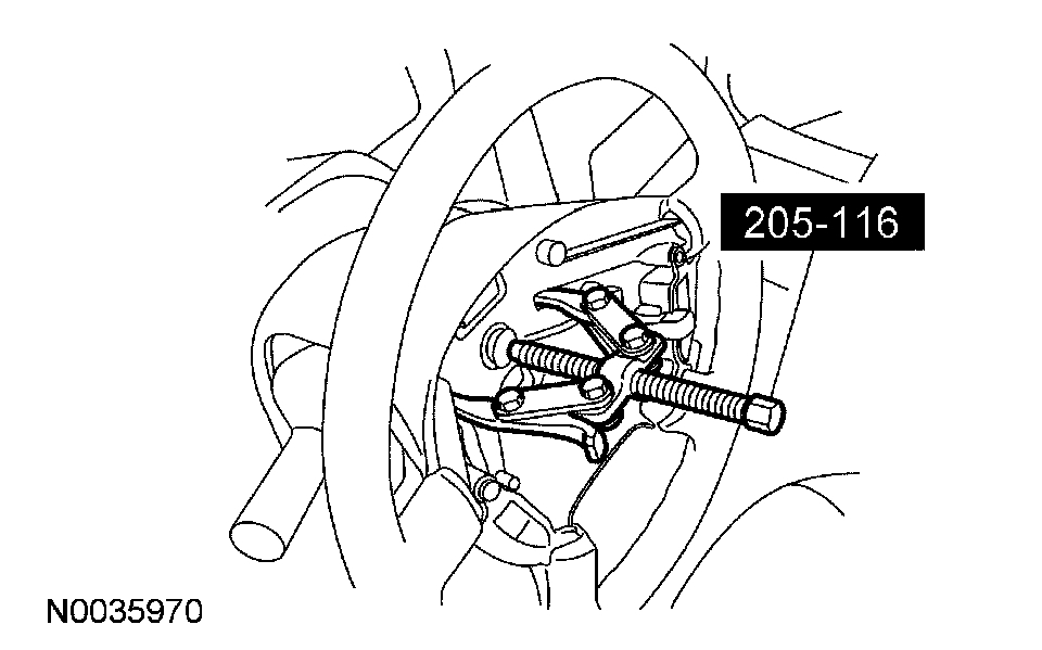
picture 13
4. CAUTION: Removing the steering wheel without using a puller can damage the column bearings.
Using the special tool, remove the steering wheel.
5. Remove and discard the steering wheel bolt.
6. Remove the steering wheel.
^ Route the wires from the clockspring through the steering wheel.
7. NOTE: A new steering wheel bolt must be installed.
To install, reverse the removal procedure.
_________________________________________
Let me know if this helps or if you have other questions.
Take care,
Joe
Images (Click to enlarge)
Feb 16, 2019 at 9:02 PM