Will not accelerate past 25 MPH

Tiny
SHORTYDAWG
  • MEMBER
  • 1993 FORD RANGER
  • 2.3L
  • 4 CYL
  • 2WD
  • AUTOMATIC
  • 100,000 MILES
Fuel pump replaced, ignition switch. Idles fine, good response from pedal but in drive wont go over 25 mph pedal to the floor. Please help.
Saturday, June 13th, 2020 AT 10:06 AM

9 Replies

Tiny
ASEMASTER6371
  • MECHANIC
  • 52,797 POSTS
Good afternoon,

I would check a couple of things to be sure they are the issue.

https://www.2carpros.com/articles/engine-has-low-power-output

Check fuel pressure. Low fuel pressure will cause this issue.

https://www.2carpros.com/articles/how-to-check-fuel-system-pressure-and-regulator

I would also check the compression to be sure the timing belt is not off time.

https://www.2carpros.com/articles/how-to-test-engine-compression

Lastly, I would check the back pressure on the catalytic converter to be sure it is not clogged.

https://www.2carpros.com/articles/how-to-test-a-catalytic-converter

Roy
Was this
answer
helpful?
Yes
No
Saturday, June 13th, 2020 AT 10:53 AM
Tiny
SHORTYDAWG
  • MEMBER
  • 41 POSTS
  • 1993 FORD RANGER
  • 2.3L
  • 4 CYL
  • 2WD
  • AUTOMATIC
  • 100,000 MILES
I have no compression gauge saw that you could take a piece of paper by tailpipe if it tries sucking in it's bad valve. Also if you take oil cap off while running it would suck it in. It tried sucking in on tailpipe but when I take off oil cap motor tries stalling and idle up and back to stalling. Is this a valve problem?Crazy I have never seen a motor try to stall by taking oil cap off put it on engine idles take it back off engine tries stalling. Engine idles fine but when I put it into drive with gas to the floor truck barely moves and chocking like it wants to go but wont. Please help.
Was this
answer
helpful?
Yes
No
Saturday, July 18th, 2020 AT 12:29 PM (Merged)
Tiny
ASEMASTER6371
  • MECHANIC
  • 52,797 POSTS
Good afternoon,

No, that does not tell you if you have a bad valve.

Do you have s vacuum gauge? You could hook it up to a vacuum source and read it at idle. It should have 18-20 inches of vacuum. The reading should be steady and not vary. If the needle fluctuates up and down, you have a burned valve.

https://www.2carpros.com/articles/engine-misfires-or-runs-rough

I attached a YouTube video of what it would look like if you have a burned valve.

https://www.youtube.com/watch?v=tsQpTVkOUD0

Roy
Was this
answer
helpful?
Yes
No
Saturday, July 18th, 2020 AT 12:29 PM (Merged)
Tiny
SHORTYDAWG
  • MEMBER
  • 41 POSTS
Okay, what would make the engine try stalling every time I take the oil cap off. This can't be normal, never seen or heard of this.
Was this
answer
helpful?
Yes
No
Saturday, July 18th, 2020 AT 12:29 PM (Merged)
Tiny
ASEMASTER6371
  • MECHANIC
  • 52,797 POSTS
If it stalls like this, you have a good chance of the intake manifold gasket is leaking vacuum. That will cause the engine to stall.

Roy

REMOVAL
1. Open hood and install protective covers.
2. Ensure ignition key is in OFF position.
3. Drain coolant from radiator.
4. Disconnect negative battery lead and secure it out of the way.
5. Remove fuel cap to relieve fuel tank pressure.

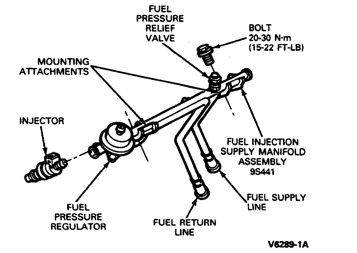
Fuel Pressure Relief Valve/Test Port
imageOpen In New TabZoom/Print

6. Release pressure from fuel system at the fuel pressure relief valve using EFI Pressure Gauge T8OL-9974-B or equivalent. The fuel pressure relief valve is located on the fuel injection supply manifold assembly in the upper RH corner of the engine compartment. To gain access to the fuel pressure relief valve, the valve cap must first be removed.

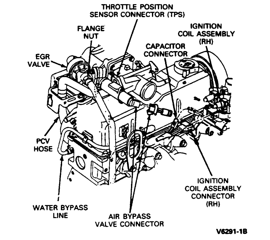
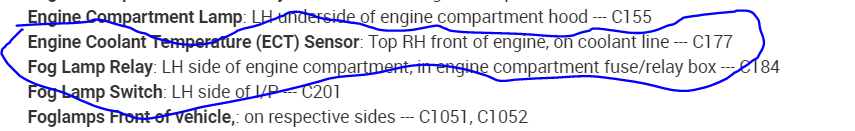
Connector/Component Locations
imageOpen In New TabZoom/Print

7. Disconnect electrical connectors at:
a. Throttle position sensor.
B. Air bypass valve.
C. Injector wiring harness at main engine harness and at water temperature indicator sensor.
D. Air charge temperature sensor.
E. Engine coolant temperature sensor.
F. Ignition control assembly.
8. Disconnect upper intake manifold vacuum fitting connections by disconnecting:
a. Vacuum lines at upper intake manifold vacuum tree. Labeling the hose locations with tape is recommended to aid reinstallation.
B. Vacuum line to EGR valve.
C. Vacuum line to fuel pressure regulator.
D. Canister purge line.
9. Remove throttle linkage shield, and disconnect throttle linkage, cruise control. Unbolt accelerator cable from bracket and position cable out of the way.
10. Disconnect air intake hose and crankcase vent hose.
11. Disconnect PCV system by disconnecting hose from fitting on underside of upper intake manifold.
12. Loosen hose clamp on water bypass line at lower intake manifold, and disconnect hose.
13. Disconnect EGR tube from EGR valve by removing flange nut.
14. Remove five upper intake manifold retaining bolts.
15. Remove upper intake manifold and air throttle body assembly.

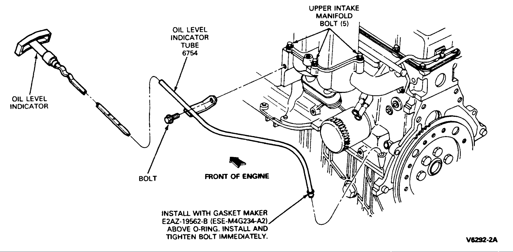
Oil Dipstick And Bracket
imageOpen In New TabZoom/Print

16. Remove engine oil dipstick bracket retaining bolt.

Springlock Coupling Remover
imageOpen In New TabZoom/Print

17. Remove springlock coupling retainer clips from fuel inlet and return fittings.

WARNING: Relieve fuel system pressure before disconnecting coupling.

18. Disconnect the push connect fitting at the fuel supply manifold and fuel return lines.
19. Disconnect the electrical connectors from all four fuel injectors and move harness aside.
20. Remove two fuel supply manifold retaining bolts. Carefully remove fuel supply manifold and injectors.

NOTE: Injectors can be removed from the fuel supply manifold at this time by exerting a slight twisting/pulling motion.

21. Remove four bottom retaining bolts from lower manifold.

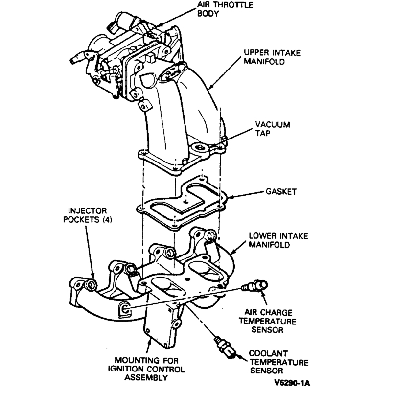
Intake Manifold Assembly
imageOpen In New TabZoom/Print

22. Remove four upper retaining bolts from lower manifold.

NOTE: The front two bolts also secure an engine lift bracket. Remove lower intake manifold assembly.

INSTALLATION
1. Clean and inspect the mounting faces of the fuel charging manifold assembly and the cylinder head. Both surfaces must be clean and flat.
2. Clean and oil manifold bolt threads.
3. Install a new gasket.
4. Position the lower manifold assembly to head and install engine lift bracket. Install four upper manifold retaining bolts fingertight.

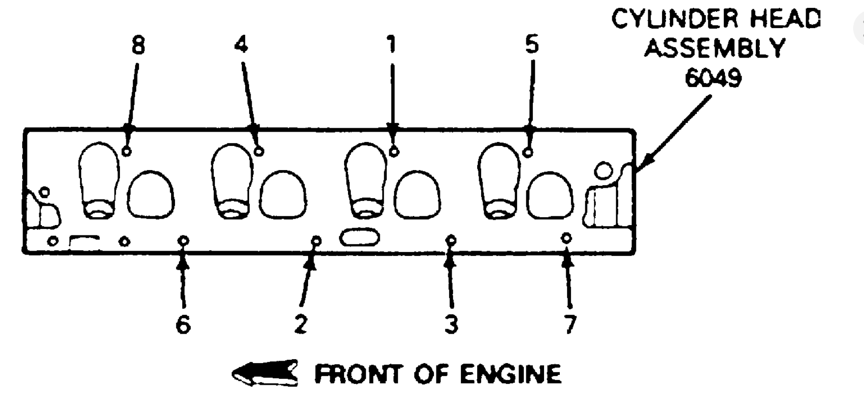
Fig. 5 Lower Intake Manifold Bolt Tightening Sequence
imageOpen In New TabZoom/Print

5. Install four remaining manifold bolts. Tighten all bolts to 20-30 Nm (15-22 ft lb) following the tightening sequence.
6. Install the fuel supply manifold and injectors with two retaining bolts. Tighten bolts to 20-30 Nm (15-22 ft lb).
7. Connect four electrical connectors to injectors.
8. Ensure that gasket surfaces of upper and lower intake manifolds are clean.
9. Place a new service gasket on the lower intake manifold assembly and place the upper intake manifold in position.

Fig. 4 Upper Intake Manifold Tightening Sequence
imageOpen In New TabZoom/Print

10. Install five retaining bolts and tighten in sequence to 20-30 Nm (15-22 ft lb).

NOTE: The three bolts with stud heads go in hole positions 2, 3 and 4.

11. Install engine oil dipstick and retaining bolt.
12. Connect fuel supply and fuel return lines to fuel supply manifold.
13. Reinstall spring-lock coupling retaining clips on fuel inlet and return fittings.
14. Connect EGR tube to the EGR valve. Tighten to 25-30 Nm (18-28 ft lb).
15. Connect the water bypass line. Tighten clamp to 1.4-2.2 Nm (12-20 in lb).
16. Connect the PCV system hose to the fitting on the underside of the upper intake manifold.
17. Connect upper intake manifold vacuum connections:
a. Vacuum lines at upper intake manifold vacuum tree.
B. EGR valve.
C. Fuel pressure regulator.
D. Canister purge line.
18. Hold accelerator cable bracket in position on upper manifold and install retaining bolts. Tighten bolt to 13.5-20.5 Nm (10-15 ft lb).
19. Install accelerator cable to bracket.
20. Connect accelerator cable and cruise control. Install throttle linkage shield.
21. Connect electrical connectors to:
a. Throttle position sensor.
B. Injector wiring harness.
C. Injector wiring harness at water temperature indicator sensor.
D. Air charge temperature sensor.
E. Engine coolant temperature sensor.
F. Ignition Control assembly.
G. Air bypass valve.
22. Connect air intake hose and crankcase vent hose.
23. Connect negative battery cable.
24. Install engine coolant.
25. Replace fuel pressure relief cap, then build up fuel pressure as follows: without starting the engine, turn key back and forth at least six times from ON to OFF position, leaving key on for 15 seconds each time; then check for fuel leaks.
26. Use EEC self-test connector to check proper EEC-IV system functioning.
27. Start engine and allow to run at idle until engine temperature stabilizes. Check for cooling system leaks.
28. Check engine idle.
29. Remove protective covers and close hood.
Was this
answer
helpful?
Yes
No
Saturday, July 18th, 2020 AT 12:29 PM (Merged)
Tiny
SHORTYDAWG
  • MEMBER
  • 41 POSTS
Ran a self check with check engine light I got 21121 and 111111. What do these codes mean?
Was this
answer
helpful?
Yes
No
Saturday, July 18th, 2020 AT 12:29 PM (Merged)
Tiny
ASEMASTER6371
  • MECHANIC
  • 52,797 POSTS
Okay, the 11 series means it passed. No issues with that one

The other is code 21 and code 211.

I posted the possibilities for the 211 below.

The 21 is for the coolant sensor for the engine by the thermostat.

https://www.2carpros.com/articles/how-a-coolant-temperature-sensor-works

None of these codes have anything to do with the bad valve issue.

You need to do a compression test.

Roy

211

REMEMBER

To prevent the replacement of good components, be aware that the following non-EEC areas may be at fault.

DIS ignition module

DIS coil pack(s)

Spark plugs and high tension cables

Crankshaft sensor.

Camshaft sensor, if equipped.

Arcing of secondary ignition components

This Pinpoint Test is intended to diagnose only the following:

Harness Circuits: IDM, DPI, SAW

Processor assembly

DESCRIPTION

The Ignition Diagnostic Monitor is an input signal to the processor that verifies spark function based on the flyback voltage created by the ignition coil primary discharge, otherwise known as TACH. This signal is transmitted from the DIS module to the processor. The IDM signal consists of a single pulse for each successful ignition event. Lack of an IDM pulse is used as an indication of intermittent and/or missing spark event.

Coolant sensor

REMOVAL

NOTE: The Engine Coolant Temperature (ECT) sensor is located in a tee in the heater water hose.

1. Disconnect negative battery cable.

2. Partially drain cooling system.

3. Disconnect ECT sensor electrical connector.

4. Remove ECT sensor from tee in heater water hose.

INSTALLATION

1. To install, reverse removal procedures.

2. Tighten the ECT sensor to 8-13 Nm (6-8 ft lb).

3. Refill cooling system.

NOTE: When the battery has been disconnected and reconnected, some abnormal drive symptoms may occur while the powertrain control module relearns its adaptive strategy. The vehicle may need to be driven 10 miles or more to relearn the adaptive strategy.
Was this
answer
helpful?
Yes
No
Saturday, July 18th, 2020 AT 12:29 PM (Merged)
Tiny
SHORTYDAWG
  • MEMBER
  • 41 POSTS
  • 1993 FORD RANGER
  • 2.3L
  • 4 CYL
  • 2WD
  • AUTOMATIC
  • 100,000 MILES
Okay, thanks guys. I have been working on this thing for a year now feel like it's something simple. Mr. Roy special thanks to you. You have been patient with me. I learned how to check for codes by reading check engine light ran test 6 times. I'm coming up with 121 which is throttle position sensor I clean and put it back on same problem. Running rough wont go over 25 mph pinging popping. So I bought a new one haven't put it on yet. So my systems. No power wont go over 25 pinging popping out of exhaust. Rough idle. Seems to wanna go but just won't. So does it sounds like the TPS and do I have to calibrate it if so how?
Was this
answer
helpful?
Yes
No
Saturday, July 18th, 2020 AT 12:29 PM (Merged)
Tiny
ASEMASTER6371
  • MECHANIC
  • 52,797 POSTS
Good morning again,

Did you ever do a compression test in all the conversations we had?

The TPS will not cause low power at all.

https://www.2carpros.com/articles/engine-has-low-power-output

Roy
Was this
answer
helpful?
Yes
No
Saturday, July 18th, 2020 AT 12:29 PM (Merged)

Please login or register to post a reply.

Sponsored links