Blend door actuator passenger?

Tiny
ERICAGAEDE
  • MEMBER
  • 2011 GMC ACADIA
  • AWD
  • AUTOMATIC
  • 134,579 MILES
How to install replacement? It still will not change between defrost and floor.
Sunday, October 15th, 2017 AT 2:37 PM

17 Replies

Tiny
KEN L
  • MASTER CERTIFIED MECHANIC
  • 42,903 POSTS
Yes, it sounds like you have a mode blend door actuator that is not working.

Here is a guide that will show you whats going on and how to fix it:

https://www.2carpros.com/articles/replace-blend-door-motor

Check out the images (Below). Please let us know what happens.
Was this
answer
helpful?
Yes
No
Monday, October 16th, 2017 AT 6:17 PM
Tiny
ERICAGAEDE
  • MEMBER
  • 2 POSTS
We have replaced with new actuators and it is still not working. We did the reset with both fuses.
Was this
answer
helpful?
Yes
No
Monday, October 16th, 2017 AT 6:50 PM
Tiny
STEVE W.
  • MECHANIC
  • 12,973 POSTS
Should only be one fuse for the non-scan tool reset. HVAC 15 amp.

Clear all DTC's.
Place the ignition switch to the "off" position.
Install the HVAC actuator.
Connect all previously disconnected components.
Remove the HVAC/ECAS fuse for a minimum of ten seconds.
Install the HVAC/ECAS fuse.
Start the vehicle.
Wait forty seconds for the HVAC control module to self-calibrate.
Verify that no DTC's have set as current DTC's.
Was this
answer
helpful?
Yes
No
+1
Monday, October 16th, 2017 AT 9:15 PM
Tiny
KEN L
  • MASTER CERTIFIED MECHANIC
  • 42,903 POSTS
Here is a wiring diagram to help us see what the problem is and what is all in the system.

Use this guide and check for power and the five volt references. I sounds like the controller is out.

https://www.2carpros.com/articles/how-to-use-a-voltmeter

Please let us know what happens.

Cheers, Ken
Was this
answer
helpful?
Yes
No
Tuesday, October 17th, 2017 AT 2:05 PM
Tiny
BROOKS KELLEY
  • MEMBER
  • 6 POSTS
I have the same problem. None of the actuators will work. They all go to default position. They have 5 volts going to actuator.
Was this
answer
helpful?
Yes
No
Monday, December 2nd, 2019 AT 10:43 AM
Tiny
BROOKS KELLEY
  • MEMBER
  • 6 POSTS
What voltage should the yellow wire read?
Was this
answer
helpful?
Yes
No
Monday, December 2nd, 2019 AT 10:44 AM
Tiny
KEN L
  • MASTER CERTIFIED MECHANIC
  • 42,903 POSTS
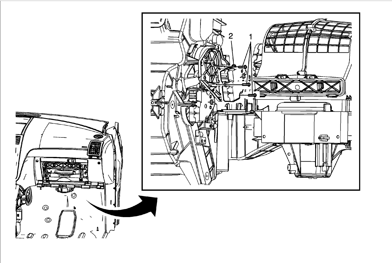
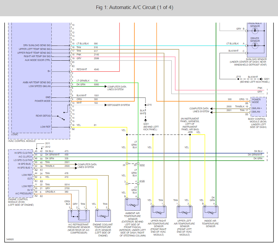
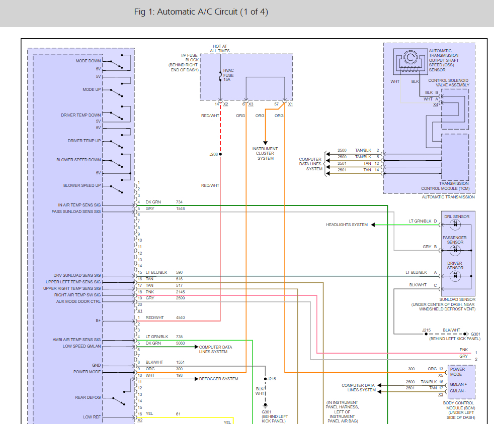
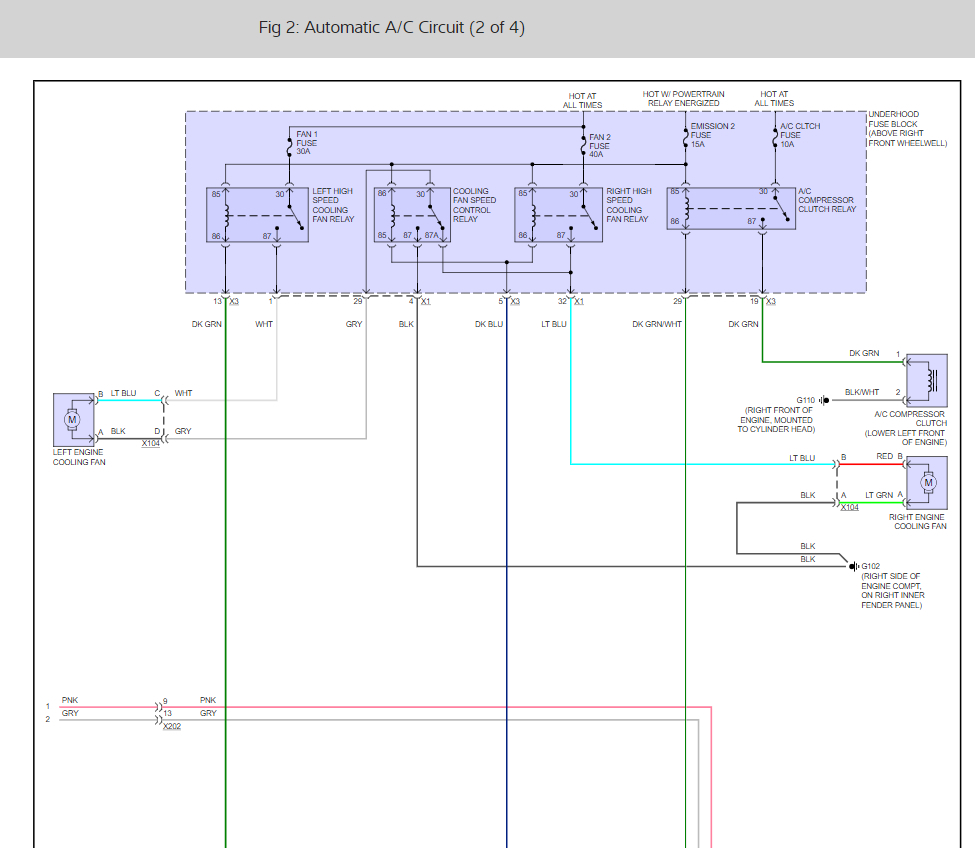
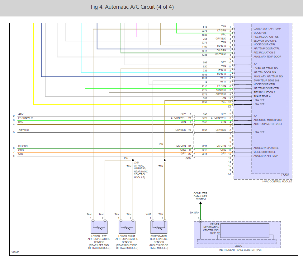
That will vary with the position of the actuator. Have you tried the system reset- calibration? Check out Steve W. Post above. If that doesn't work it sounds like the control module is out here is how you replace it. Check the diagrams below.

HVAC System Control Module Programming and Setup

Each of the following service procedures may require programming or setup procedures to be performed on the HVAC control module or HVAC actuators.

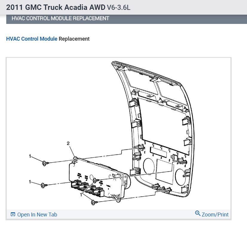
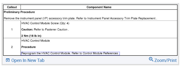
HVAC Control Module Replacement

If the HVAC control module is replaced it must be programmed with the latest operating software and vehicle calibrations. Refer to Service Programming System (SPS) (See: Vehicle > Programming and Relearning > Service Programming System (SPS)).

HVAC Control Module Reprogramming

Do not reprogram the HVAC control module, unless directed by a service procedure, or a service bulletin.

Reprogram HVAC Control Module-Refer to Service Programming System (SPS) (See: Vehicle > Programming and Relearning > Service Programming System (SPS)).

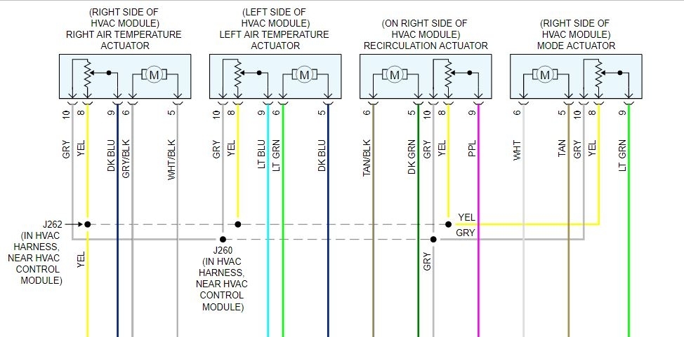
Actuator Replacement

If an actuator is replaced, the following procedure must be performed:

* Re-Calibrating Actuators-Refer to Actuator Recalibration (See: Heating and Air Conditioning > Programming and Relearning > HVAC - Manual) for the manual system.
* Re-Calibrating Actuators-Refer to Actuator Recalibration (See: Heating and Air Conditioning > Programming and Relearning > HVAC - Automatic) for the automatic system.

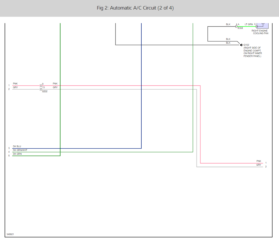
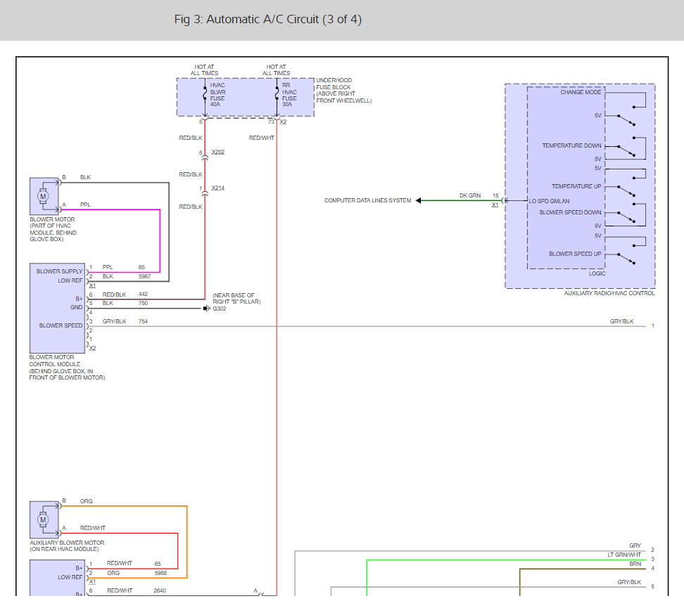
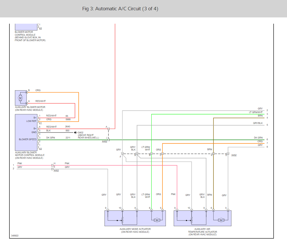
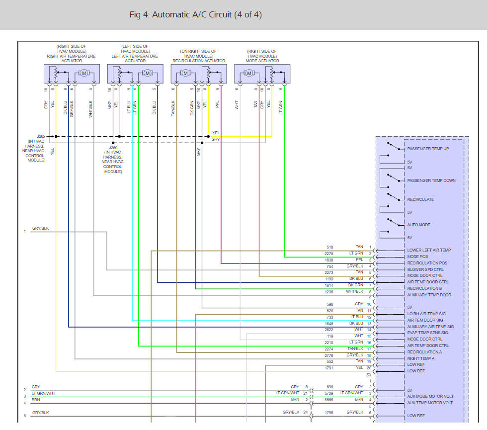
Check out the diagrams (below). Please let us know what happens.
Was this
answer
helpful?
Yes
No
Monday, December 2nd, 2019 AT 10:57 AM
Tiny
STEVE W.
  • MECHANIC
  • 12,973 POSTS
If none of the actuators move in response to the controller, the fault is likely in the controller. The mode and blend actuators are simple motors with a feedback circuit and each has a different control feed and return signal so if all of them are not working the common item is the controller. Voltage wise the Gray wire should be the 5 volt feed. The Yellow wire is ground (low reference) from pin 20 on connector X3 on the controller and the signal wires depend on which actuator you are testing. See the wiring diagram attached for those colors.
Was this
answer
helpful?
Yes
No
Monday, December 2nd, 2019 AT 4:17 PM
Tiny
BROOKS KELLEY
  • MEMBER
  • 6 POSTS
I had gm dealership replace controller with new and still didn't work.
Was this
answer
helpful?
Yes
No
Monday, December 2nd, 2019 AT 4:52 PM
Tiny
STEVE W.
  • MECHANIC
  • 12,973 POSTS
Did it work when they installed it then stop working? I would think they would have tested it before returning it. Which controller do you have the automatic one with digital readout or the manual version? If it worked then stopped I would still say it is controller related, either the wiring or the power to it. Have you tried the rest above? What did it do?
Was this
answer
helpful?
Yes
No
Tuesday, December 3rd, 2019 AT 4:05 PM
Tiny
BROOKS KELLEY
  • MEMBER
  • 6 POSTS
It never worked. They put the old controller back in. I told them I didn't want to spend any more time on it. It has the automatic control module. The fan speed, and everything else works besides the actuators.
Was this
answer
helpful?
Yes
No
Tuesday, December 3rd, 2019 AT 4:25 PM
Tiny
STEVE W.
  • MECHANIC
  • 12,973 POSTS
Okay, try this, take a jumper wire and connect the yellow wire (low ref) to a good ground. Test the system. Any change? The sensors in each actuator share the 5 volt and the ground, you said you found that was there already. You say the actuators return to the default positions, is that after you move them or do they not move at all? They use simple revering polarity to move them, connect your volt meter across the drive wires and see if you get a voltage when you select that actuator. If not then we will need to look at the powers and grounds into the controller.
Was this
answer
helpful?
Yes
No
Tuesday, December 3rd, 2019 AT 6:43 PM
Tiny
BROOKS KELLEY
  • MEMBER
  • 6 POSTS
Should the yellow wires that are common to all actuators read continuity to ground?
Was this
answer
helpful?
Yes
No
Tuesday, December 3rd, 2019 AT 7:29 PM
Tiny
KEN L
  • MASTER CERTIFIED MECHANIC
  • 42,903 POSTS
Does the controller light up? Lets test power and grounds by using the wiring diagrams above. here is a guide:

https://www.2carpros.com/articles/how-to-check-wiring

Please run down this guide and report back.

Was this
answer
helpful?
Yes
No
Wednesday, December 4th, 2019 AT 11:33 AM
Tiny
BROOKS KELLEY
  • MEMBER
  • 6 POSTS
Yes. Everything on the controller is working. It will control the fan in auto and manual. All of the buttons function. The only thing that it will not do is make the actuators control properly. It sends them to default position
Was this
answer
helpful?
Yes
No
Wednesday, December 4th, 2019 AT 12:39 PM
Tiny
KEN L
  • MASTER CERTIFIED MECHANIC
  • 42,903 POSTS
And you have replaced the controller and did the relearn? Must be a wiring issue or one of the actuators is shorted out causing the default. I would unplug one at a time to see if you can get the system to respond.
Was this
answer
helpful?
Yes
No
Wednesday, December 4th, 2019 AT 1:00 PM
Tiny
STEVE W.
  • MECHANIC
  • 12,973 POSTS
Yes the yellow wires should all read the same and they should read as the low reference which is a ground buss inside the control module. It is pin 20 in connector X3 should be next to another low reference Tan wire in pin 19 of the same connector. The yellow wires from each actuator come back to a splice in the harness not far from the controller connector.
Was this
answer
helpful?
Yes
No
Wednesday, December 4th, 2019 AT 9:12 PM

Please login or register to post a reply.

Sponsored links