No Scanner communication why?

Tiny
BIGJAY77
  • MEMBER
  • 2006 CHEVROLET SILVERADO
  • V8
  • 4WD
  • AUTOMATIC
  • 166,580 MILES
I have a check engine light on and when I hook to a scanner I get nothing. The scanner is not recognizing that its even plugged up. Is there possibly a fuse for the OBD connector? (Hopefully?LOL) Thanks guys!
Do you
have the same problem?
Yes
No
Monday, January 31st, 2011 AT 3:40 PM

16 Replies

Tiny
HMAC300
  • MECHANIC
  • 48,606 POSTS
Check fuses for ecm as you may have a blown fuse. it's a 15 amp in the underhood electrical box.it will say cig ltr. then check at 16 on aldl for power with key on..... #4 is the ground check that as well. Here is a guide to help with the fuse location in the diagrams below.

https://www.2carpros.com/articles/how-to-check-a-car-fuse

Check out the diagrams (Below). Please let us know what happens.
Was this
answer
helpful?
Yes
No
Tuesday, February 1st, 2011 AT 12:30 AM
Tiny
BIGJAY77
  • MEMBER
  • 4 POSTS
Thank you very much hmac300! Yalls help is fantastic. I love the internet!
Was this
answer
helpful?
Yes
No
+2
Tuesday, February 1st, 2011 AT 12:34 AM
Tiny
DOAUSI
  • MEMBER
  • 16 POSTS
  • 2006 CHEVROLET SILVERADO
  • V6
  • 2WD
  • AUTOMATIC
  • 79,000 MILES
The engine light has come on and when I use the code reader it shows "NO CONNECTION". I have tried several of the correct code readers and they read the same. How do I obtain a reading?

Thanks.
Was this
answer
helpful?
Yes
No
Wednesday, May 5th, 2021 AT 1:57 PM (Merged)
Tiny
JACOBANDNICKOLAS
  • MECHANIC
  • 107,922 POSTS
Hi and thanks for using 2carpros.com

Most times, either there is a power issue to the data link connector (DLC) or a bad ground. With that in mind, I need you to check the following pins in the DLC. I attached a picture of the DLC to help you identify the pins and their locations. See pic 1

First, pin 16 is battery power. It should have 12 volts all the time. You can check it with a test light or better yet, a volt meter.

Next, I need you to check pins 4 and 5 for ground. You will need a multi meter to check continuity.

Here are a few links that may help.

https://www.2carpros.com/articles/how-to-use-a-test-light-circuit-tester

https://www.2carpros.com/articles/how-to-use-a-voltmeter

https://www.2carpros.com/articles/how-to-check-wiring

If there is no power to pin 16, check fuse ( and don't laugh ) it is the same one that powers the cigarette lighter. See pic 2. If you were to follow the highlighted wire, it goes to pin 16.

If you have power and no ground, there are two places you have to check. Take a look at pic 3. It shows the entire data link connector. Locate pins 4 and 5 and follow the highlighted wires to ground location. It describes where they are located.

I have a feeling like most vehicles, the cigarette lighter doesn't work because of a blown fuse which results in no power to the DLC. LOL

Check these things and let me know what you find.

Take care,
Joe
Was this
answer
helpful?
Yes
No
+5
Wednesday, May 5th, 2021 AT 1:57 PM (Merged)
Tiny
DOAUSI
  • MEMBER
  • 16 POSTS
Thank You Joe, Will get on the job first thing tomorrow. I will also keep you updated as to my findings. Thanks Again! DoAuSi
Was this
answer
helpful?
Yes
No
Wednesday, May 5th, 2021 AT 1:57 PM (Merged)
Tiny
JACOBANDNICKOLAS
  • MECHANIC
  • 107,922 POSTS
Not a problem. I will watch for your reply.

Good luck,
Joe
Was this
answer
helpful?
Yes
No
+1
Wednesday, May 5th, 2021 AT 1:57 PM (Merged)
Tiny
DANIELS16
  • MEMBER
  • 12 POSTS
  • 2004 CHEVROLET SILVERADO
  • 5.3L
  • V8
  • 4WD
  • AUTOMATIC
  • 150,000 MILES
1 Month ago I bought my 2004 Silverado 1500. It has true duals and a leveling kit. When I bought the truck it was a 300 mile trip home that I took it on. It had absolutely no problem except for the engine light was on which I figured was just because of the true dual exhaust. It drove good for a week and now I am having a multitude of error codes showing up when scanned and problems being caused. When I hit speeds 60mph+ it puts the truck in an reduced engine power mode. It shuts my motor down to a rough idle. I have to pull over turn the key off for 10 seconds then I can turn it back on and its okay. I am also having an issue with when I have a passenger get in it turns on my brake light as well as my abs light and states that I need to service the brake system. Now just yesterday it is giving me another code and reading saying that I need to service the four wheel drive. The truck has been in what seems to be a low speed front end collision as it new front fenders, the bumper was bent and a few other things im sure. The previous owner didn't know about the accident. He told me he had problem with the 4wd but replaced the push button switch board inside the cab and that it fixed it. I read online where the reduced engine problem was from a bad throttle position sensor so I replaced the sensor and the wiring harness. It did nothing. I am wondering if this could just be one huge wiring issue from the accident or is it just a multitude of small problems I need to fix.

The Codes are:
U1000 -Class 2 Communication Malfunction Conditions
U1016 -Loss of Class 2 Communication with VCM
U1041 -Loss Communications with Electronic Brake Control Module
U1028 -Loss of Communication with Class 2 Devices
U0107 -Loss of Communication with Throttle Actuator Module
C0327- Encoder CIrcuit
U1301 - Class 2 Short to Battery

I NEED HELP!
Was this
answer
helpful?
Yes
No
Wednesday, May 5th, 2021 AT 1:57 PM (Merged)
Tiny
HMAC300
  • MECHANIC
  • 48,606 POSTS
This has been bugging the crap out of me it happens to us guys that fix cars. You said this has true duals meaning exhaust. Does this have one of those things plugged into the aldl or where you hook the scanner up inside the car? If it does take it out and see if you have the same problems. A lot of these GM products get screwed up when these things are plugged into the car. Either that or there is some kind of wiring issue with the passenger seat. That is causing this or any other place that eh wiring harness has been modified like an alarm system that was installed that isn't factory unit.
Was this
answer
helpful?
Yes
No
Wednesday, May 5th, 2021 AT 1:57 PM (Merged)
Tiny
DANIELS16
  • MEMBER
  • 12 POSTS
I think the throttle actuator is the problem and because it is not functioning properly it is causing other codes to pop up. The power train control module communicates with the TAC and because the TAC isn't working well the power train core appeared. I checked all of the wiring between the tps sensor and the TAC and also between the pedal position sensor and the TAC and all wires have good continuity. I just ordered a TAC online and hopefully that will fix it!
Was this
answer
helpful?
Yes
No
+1
Wednesday, May 5th, 2021 AT 1:57 PM (Merged)
Tiny
DJBECKETT
  • MEMBER
  • 2 POSTS
  • 2002 CHEVROLET SILVERADO
  • 6 CYL
  • 2WD
  • AUTOMATIC
  • 82,000 MILES
My actron code scanner won't come on when plugged in, and the security dahboard light goes on and off when plugged in (never have seen the security light before). I know the scanner works; I used it on our 2000 Pontiac firebird. Two other friends tried their scanners, same results. I had a service engine warning light recently, and purchased the scanner to determine where to start.
Was this
answer
helpful?
Yes
No
Wednesday, May 5th, 2021 AT 1:57 PM (Merged)
Tiny
ROWTIEAR
  • MEMBER
  • 91 POSTS
Check ecm fuse and other fuses
Was this
answer
helpful?
Yes
No
Wednesday, May 5th, 2021 AT 1:57 PM (Merged)
Tiny
DJBECKETT
  • MEMBER
  • 2 POSTS
The ecm fuses were good. I knew the cigar fuse was blown, and went straight to that. That fixed it! The code scanner works! Thanks!
Was this
answer
helpful?
Yes
No
Wednesday, May 5th, 2021 AT 1:58 PM (Merged)
Tiny
JOHN951
  • MEMBER
  • 1 POST
  • 2000 CHEVROLET SILVERADO
  • 0.6L
  • V8
  • 4WD
  • AUTOMATIC
  • 150,000 MILES
I just bought an OBD2 scanner (0S601 by OBDScar) it works on my wife’s Honda but will show communication error on my truck. When I take my truck to AutoZone their scanner has no problem running a diagnostic. Is it the scanner I bought or some issues with my electric system? I do have some aftermarket accessories radio and remote start. I don’t understand why one scanner works on my truck and another doesn’t. The scanner says that the software was updated this year so not sure if that would be the issue. I guess I’m asking what would be easier getting a new scanner or trying to figure out why the one I have isn’t working?

Thanks for any advice or help!
Was this
answer
helpful?
Yes
No
Wednesday, May 5th, 2021 AT 1:58 PM (Merged)
Tiny
KASEKENNY
  • MECHANIC
  • 18,907 POSTS
Hi,

I can jump in and help answer that. Many people have reported good things about the Autel OBD 2 scanner but I have seen more and more apps with just a DLC plug in. These are cheap and easy to use. Most OEMs use this pod type tool so they are dependable.

No matter what you get just make sure you can not only read codes but communicate with the ABS module and also look at live data. Reading codes is great but we need to be able to look at what the sensors are doing if we want to properly diagnose most issues.
Was this
answer
helpful?
Yes
No
Wednesday, May 5th, 2021 AT 1:58 PM (Merged)
Tiny
HELPGORDO921
  • MEMBER
  • 3 POSTS
  • 1999 CHEVROLET SILVERADO
  • 5.3L
  • V8
  • 4WD
  • AUTOMATIC
  • 243,373 MILES
OBD2 diagnostic port is not communicating with scanner. Truck will not pass emissions until communication is established.
Was this
answer
helpful?
Yes
No
Wednesday, May 5th, 2021 AT 1:58 PM (Merged)
Tiny
ASEMASTER6371
  • MECHANIC
  • 52,797 POSTS
Good afternoon,

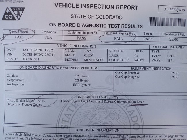
Something I saw in the report is a clue.

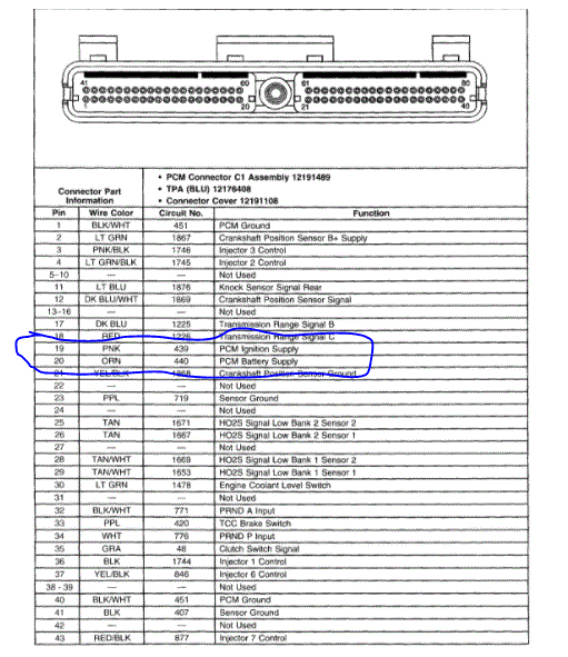
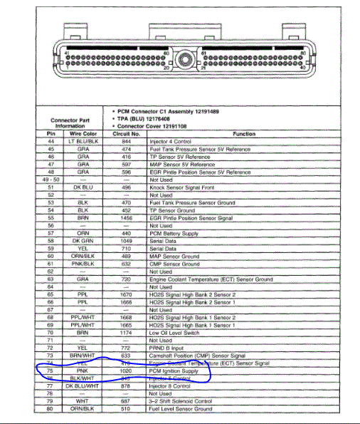
The check engine light apparently does not work as well as no communication. With those 2 issues present that means either there is no power to the ECM or the ECM itself is no good.

https://www.2carpros.com/articles/checking-a-service-engine-soon-or-check-engine-light-on-or-flashing

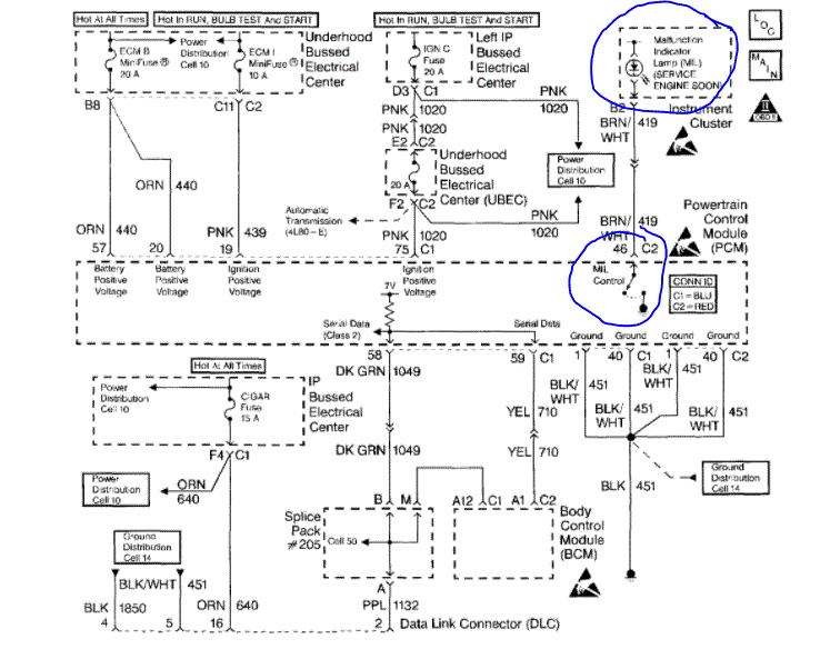
I attached a connector diagram of the ECM. I circled the pins that need to have voltage with the key on. Verify this voltage to those pins.

https://www.2carpros.com/articles/how-to-check-wiring

Roy

Circuit Description
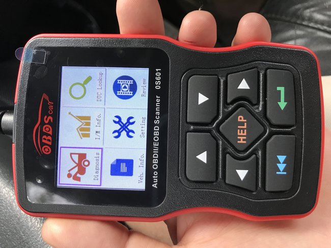
Use a properly functioning scan tool with the diagnostic tables. DO NOT use the Clear Info function unless instructed by a diagnostic procedure.

Important: This vehicle, equipped with a Powertrain Control Module (PCM), utilizes an Electrically Erasable Programmable Read Only Memory (EEPROM). Program the new PCM when the diagnostics call for replacement of the PCM. When the PCM or BCM is replaced the PCM Password Learn procedure must be performed. Refer to DTC P1631 Theft Deterrent Password Incorrect. See: A L L Diagnostic Trouble Codes ( DTC ) > P Code Charts P1631
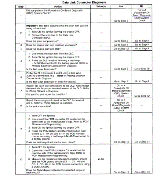
Test Description
The numbers below refer to the step numbers on the diagnostic table.
3. An engine that just cranks and does not attempt to start indicates that the PCM is not powered-up.
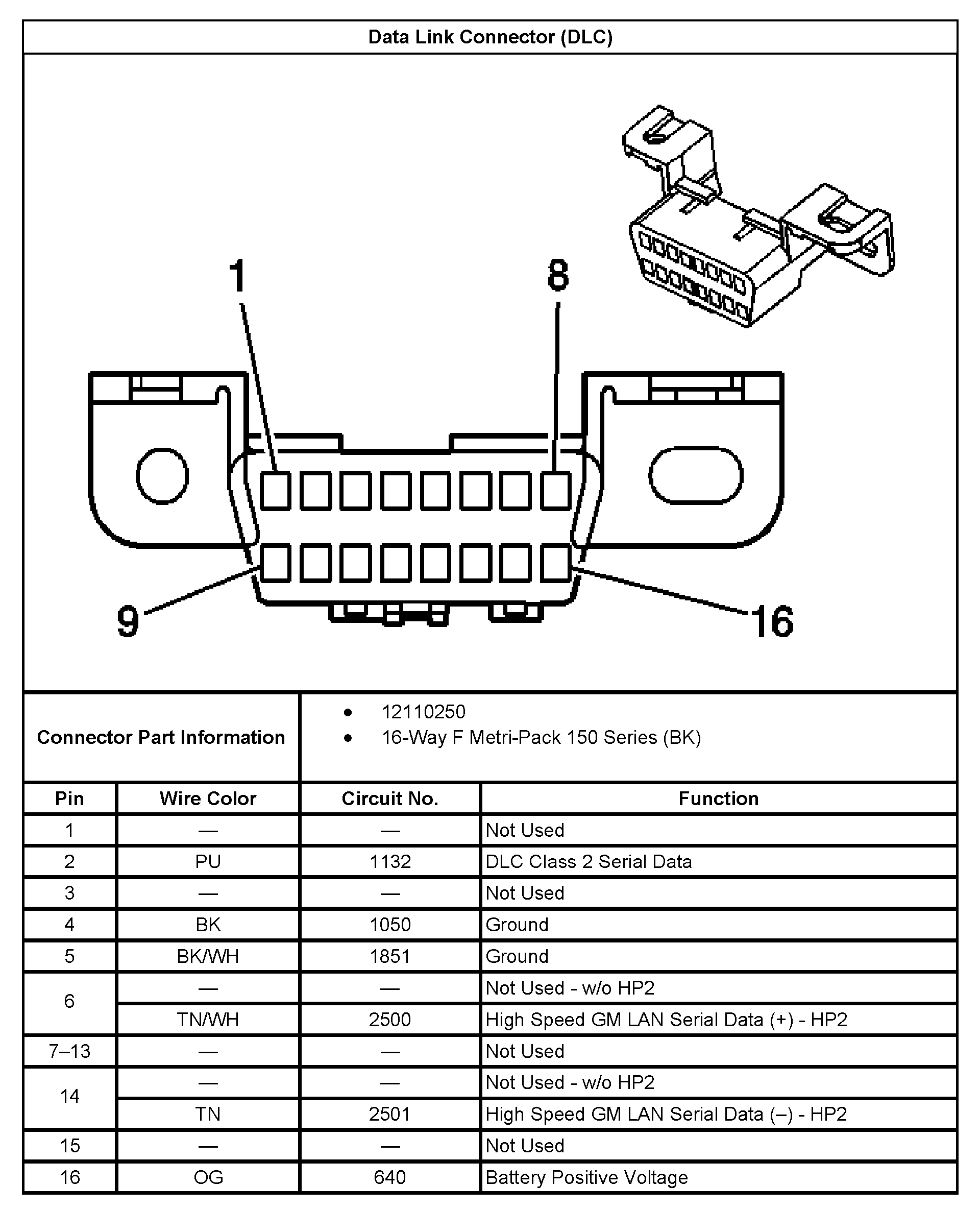
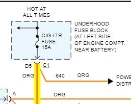
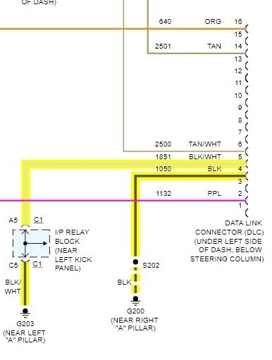
5. This step is checking for a B+ supply to the Data Link Connector (DLC).
6. A ground must be available at both terminals for the scan tool to function properly.
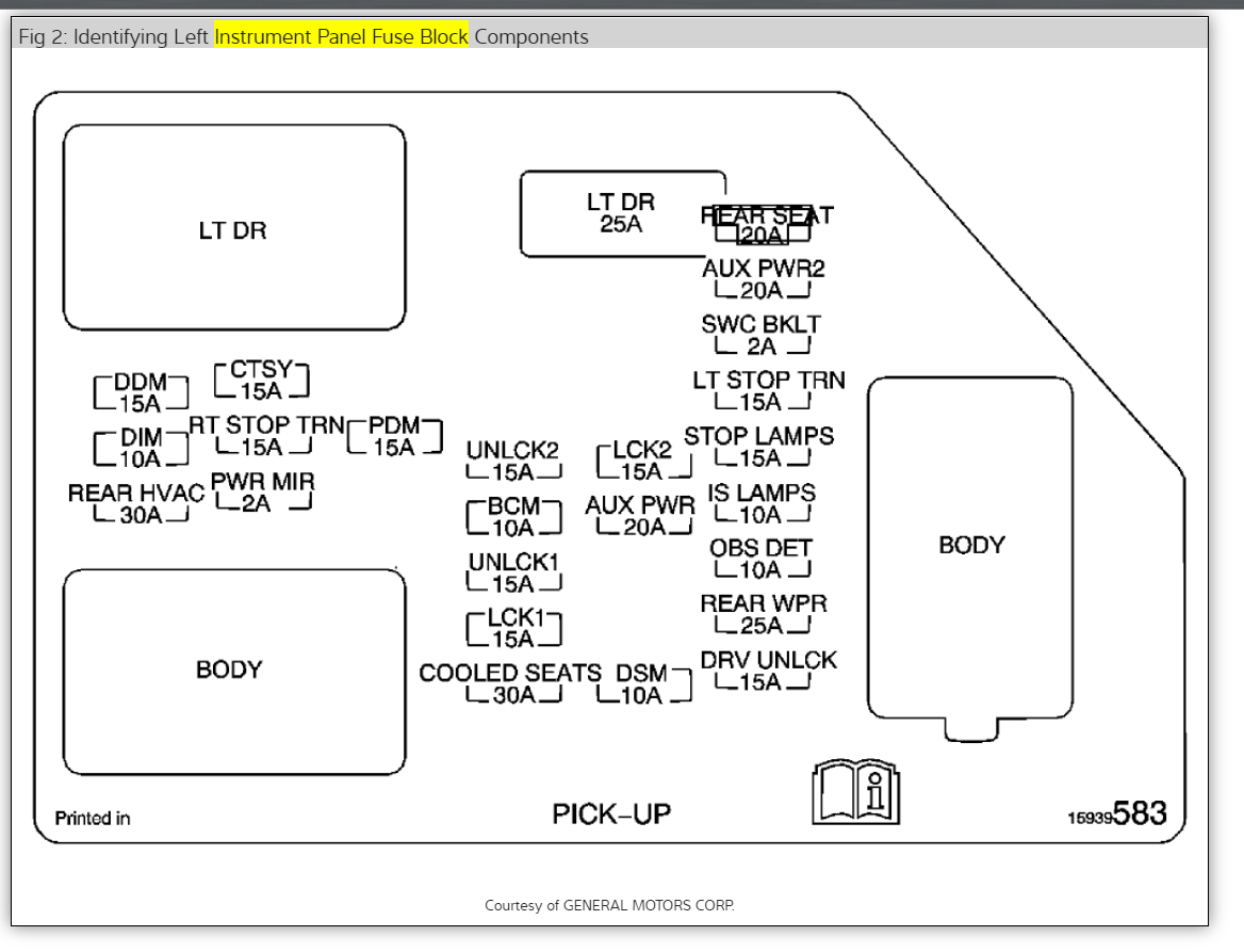
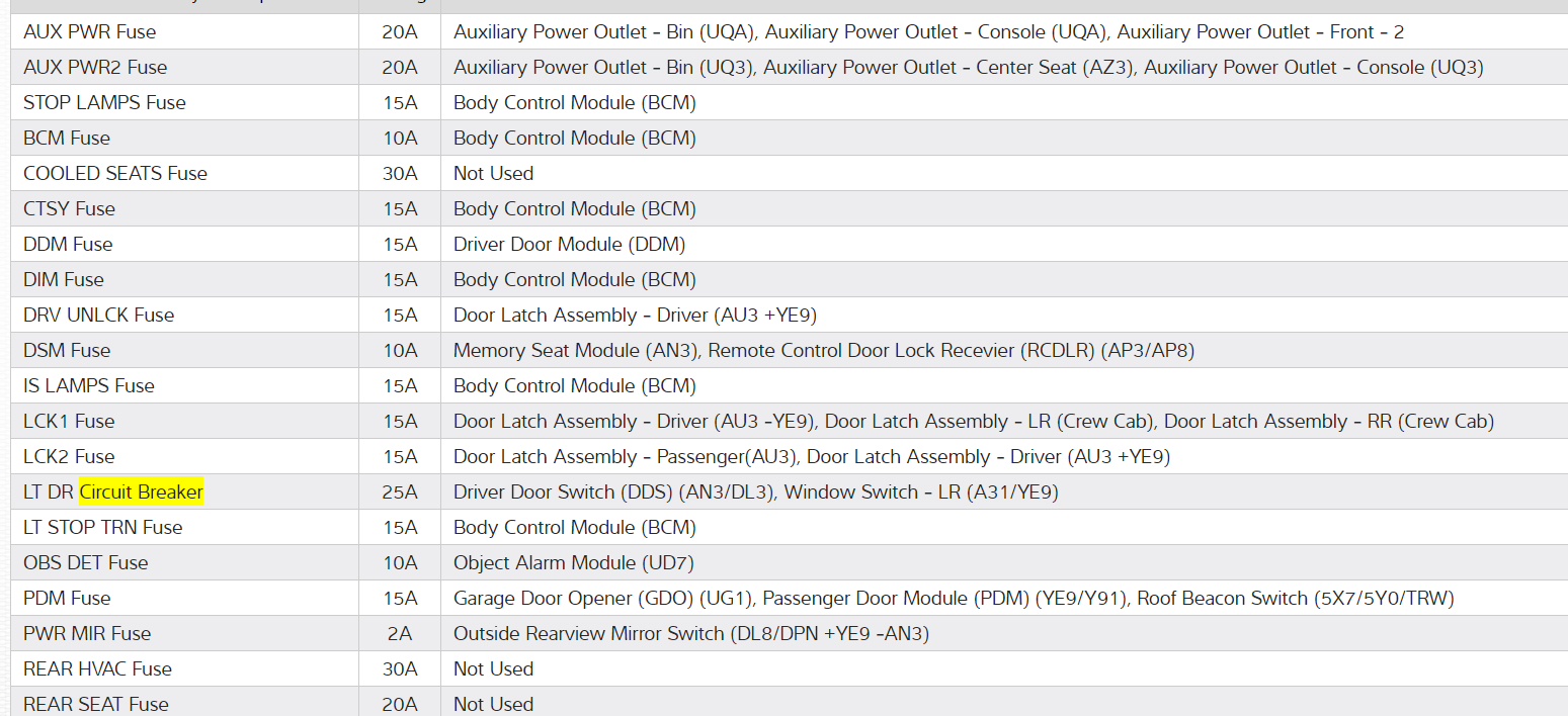
9. A no start condition occurs when the fuse(s) for the battery or ignition feed circuits is open. The MIL is inoperative when the battery and ignition feed circuit fuses open. Inspect the circuits for being grounded when either of these fuses open.
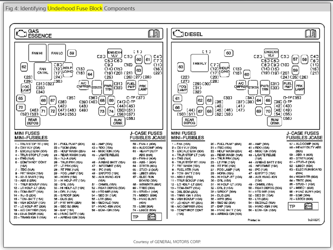
12. The scan tool does not communicate when the C100 connector is open. The C100 connector is located under the under hood electrical center.
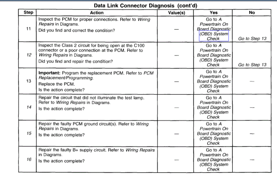
14. If the test lamp does not illuminate for a circuit, inspect the fuse for being open. If the fuse is open, inspect the circuit for a short to ground.
15. Inspect for an open ground circuit. Inspect G103 located on the right rear of the engine block for an open or for a poor connection.
16. Inspect for an open fuse that supplies the DLC. If the fuse is open, repair the grounded circuit.

ECM

Service of the PCM should normally consist of either replacement of the PCM or EEPROM programming. If the diagnostic procedures call for the PCM to be replaced, the PCM should be checked first to see if it is the correct part. If it is, remove the faulty PCM and install the new service PCM.

THE SERVICE PCM EEPROM WILL NOT BE PROGRAMMED. DTC P0601 and P0602 indicates the EEPROM is not programmed or has malfunctioned.

IMPORTANT: The following must be performed anytime the PCM is replaced:

1. Programming of the EEPROM
2. The PCM Password learn procedure. Refer to DTC P1631 Theft Deterrent Password Incorrect.
3. The Idle Learn Procedure. Refer to PCM Idle Learn Procedure.
4. The CKP System Variation Learn Procedure. Refer to CKP System Variation Learn Procedure.
5. Reset the Engine Oil Life monitor. Refer to Engine Oil Life Monitor Reset Procedure.
6. The Functional Check

The following must be performed anytime the PCM is disconnected, loses power, or is reprogrammed.
1. The Idle Learn Procedure. Refer to PCM Idle Learn Procedure.
2. The Functional Check

IMPORTANT: To prevent internal PCM damage, the ignition must be OFF when disconnecting or reconnecting power to the PCM (for example, battery cable, PCM pigtail, PCM fuse, jumper cables, etc.).

imageOpen In New TabZoom/Print

REMOVAL PROCEDURE

IMPORTANT: Remove any debris from the PCM connector surfaces before servicing the PCM. Inspect the PCM module connector gaskets when diagnosing/replacing the PCM. Ensure that the gaskets are installed correctly. The gaskets prevent contaminate intrusion into the PCM.

1. Release the PCM cover mounting holes (1, 5) away from the mounting tabs on the PCM mounting bracket.
2. Release the PCM cover (8) from the mounting bracket.
3. Remove the PCM cover.

NOTE: Do not touch the connector pins or soldered components on the circuit board in order to prevent possible electrostatic discharge (ESD) damage to the PCM.

NOTE: In order to prevent internal damage to the PCM, the ignition must be OFF when disconnecting or reconnecting the PCM connector.

4. Disconnect the PCM harness connectors (6).
5. Release the spring latch (2) from the PCM.
6. Release the PCM mounting tabs (3) from the PCM.
7. Remove the PCM (4) from the engine compartment.

INSTALLATION PROCEDURE

NOTE: Do not touch the connector pins or soldered components on the circuit board in order to prevent possible electrostatic discharge (ESD) damage to the PCM.

NOTE: In order to prevent internal damage to the PCM, the ignition must be OFF when disconnecting or reconnecting the PCM connector.

1. Install the PCM (4) to the PCM mounting bracket (7) ensuring that the mounting tabs are engaged.
2. Secure the spring latch (2) to the PCM.
3. Connect the PCM connectors (6) to the PCM (4).

Tighten
Tighten the PCM connector end fasteners to 8 N.m (70 lb in).

4. Install the PCM cover (8) to the PCM mounting bracket (7), ensuring the mounting tabs on the PCM mounting bracket are engaged into the mounting holes in the PCM cover.

5. If a new PCM is being installed, program the EEPROM.

PCM Programming
1. Setup - Ensure that the following conditions have been met:
The battery is fully charged.
The ignition is ON.
2. Program the PCM using the tatest software matching the vehicle. Refer to Techline terminal/equipment users instructions.
3. If the PCM fails to program, proceed as follows:
Ensure that all PCM connections are Ok.
Check the Techline terminal/equipment for the latest software version.
Attempt to program the PCM. If the PCM still cannot be programmed properly, replace the PCM. The replacement PCM must be programmed.
4. Perform the PCM Password learn procedure. Refer to DTC P1631 Theft Deterrent Password Incorrect
5. Perform the Idle Learn Procedure. Refer to PCM Idle Learn Procedure.
6. Perform the CKP System Variation Learn Procedure. Refer to CKP System Variation Learn Procedure.
7. Reset the Engine Oil Life monitor. Refer to Engine Oil Life Monitor Reset Procedure.
8. The Functional Check

Functional Check
1. Clear the Diagnostic Trouble Codes (DTCs).
2. Perform the On-Board Diagnostic System Check.
3. Start the engine and idle for one minute.
4. Use the scan tool in order to check for DTCs.
Was this
answer
helpful?
Yes
No
Wednesday, May 5th, 2021 AT 1:58 PM (Merged)

Please login or register to post a reply.

Sponsored links