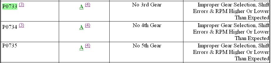
Here are the diagnostic procedures. For such codes to occur, you would have the symptoms described and it could either be due to electrical or mechanical faults.
TEST A: SHIFT & TORQUE CONVERTER CLUTCH SOLENOIDS
NOTE:
After each service or repair procedure has been completed, reconnect all components. Clear DTCs and repeat QUICK TEST. Ensure all EEC-V systems are working properly and DTCs are no longer present.
1. Ensure ignition switch is in OFF position. Place gearshift lever in "P" position. Ensure transmission harness connector is fully seated, and terminals are fully engaged in connector and in good condition. Connect NGS tester to DLC. Enter TRANS-BENCH MODE. See
OUTPUT STATE CONTROL MODES under SELF-DIAGNOSTIC SYSTEM.
2. If vehicle enters TRANS-BENCH MODE, remain in TRANS-BENCH MODE and go to next step. If vehicle does not enter TRANS-BENCH MODE, repeat procedure. If vehicle still does not enter TRANS-BENCH MODE, see
SCAN TOOL UNABLE TO COMMUNICATE under SELF-DIAGNOSTIC SYSTEM.
3. Perform SS1, SS2, SS3, SS4 & TCC SOLENOIDS (BENCH MODE) tests. See
OUTPUT STATE CONTROL MODES under SELF-DIAGNOSTIC SYSTEM. Select suspect PIDs (SS1, SS2, SS3, SS4 or TCC) to be monitored. Select suspect solenoid ON and press SEND. Monitor PIDs for change of state while wiggling wiring and connectors to transmission. If suspect solenoid PID changes from ON to OFF state, repair affected circuit and retest system. If suspect solenoid PIDs do not change from ON to OFF state, go to next step.
4. Remain in TRANS-BENCH MODE. Monitor each solenoid PID while changing solenoid state from ON to OFF. If all solenoids turn on and off when commanded and an audible click can be heard, go to next step. If any solenoid does not turn on and off when commanded and an audible click cannot be heard, go to step 6 .
5. Perform Gear and TCC mode tests in TRANS-DRIVE MODE under OUTPUT STATE CONTROL MODES under SELF-DIAGNOSTIC SYSTEM. If transmission does not upshift or downshift, or TCC does not engage or disengage when commanded, go to next step. If transmission upshifts and downshifts and TCC engages and disengages when commanded, clear DTCs. Road test vehicle. Retest system. If concern still exists, see appropriate symptom in appropriate SYMPTOM DIAGNOSIS under TROUBLE SHOOTING . If PIDs and voltage readings change state while cycling solenoids from on to off, and an audible "click" can be heard from solenoid, go to next step. If PIDs and voltage readings do not change state while cycling solenoids from on to off, and an audible "click" from solenoid is not heard, repair open or shorted circuit in harness, solenoid or PCM.
6. Ensure ignition switch is in OFF position. Remove transmission oil pan. Inspect all wires and connectors to solenoids for damage. Turn ignition switch to ON position. Connect positive lead from DVOM to suspect solenoid VPWR terminal and negative lead to chassis ground. Measure voltage between each solenoid VPWR terminal and chassis ground. Voltage should be more than 10 volts. If voltage is as specified, go to next step. If voltage is not as specified, repair open or short circuit in affected VPWR wire. Retest system.
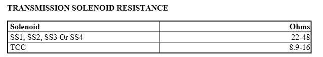
7. Leave DVOM positive lead connected to solenoid VPWR terminal. Connect DVOM negative lead to signal terminal of suspect solenoid. With NGS tester connected, perform SS1, SS2, SS3, SS4 & TCC SOLENOIDS (BENCH MODE) tests. Select suspect PIDs (SS1, SS2, SS3, SS4 or TCC) to be monitored. Select suspect solenoid ON and press SEND. Monitor PIDs and voltage readings for change of state while cycling solenoids from on to off state (listen for audible "click" from solenoid). If PIDs and voltage readings change state while cycling solenoids from on to off, and an audible "click" can be heard from solenoid, go to next step. If PIDs and voltage readings do not change state while cycling solenoids from on to off, and an audible "click" from solenoid is not heard, repair open or shorted circuit in harness, solenoid or PCM. Retest system. Disconnect suspect solenoid connector at solenoid. Measure resistance between both solenoid terminals. See TRANSMISSION SOLENOID RESISTANCE table. If resistance is within specification, go to next step. If resistance is not within specification, replace affected solenoid. Retest system.
9. Check for continuity between chassis ground and both solenoid terminals. If continuity exists, replace affected solenoid. Retest system. If continuity does not exist, see appropriate shift or TCC solenoid symptom. See appropriate symptom in appropriate SYMPTOM
DIAGNOSIS under TROUBLE SHOOTING .
© 2008 Mitchell Repair Information Co., LLC.
Images (Click to enlarge)
Jan 11, 2011 at 7:23 PM