Engine wiring diagrams

Tiny
05ACURATL
  • MEMBER
  • 2005 ACURA TL
  • 3.2L
  • V6
  • 2WD
  • AUTOMATIC
  • 250,000 MILES
I don't hear the fuel pump prime. Tried replacing the fuel pump relay under dash fuse box but that didn't fix the problem. I replaced practically every relay (including main relays igp 1 and 2) and all fuses both under the dash and under the hood. FYI, obd2 scanner is unable to communicate with ECM. Also, the immobilizer key is flashing. I tried to start the car using the Brake Code from dealership, the immobilizer key went solid (that should be indication that immobilizer is temporarily disabled) but I still don't hear the fuel pump prime and still left with crank no start condition. Can someone suggest a solution and also provide me with the wiring diagram from engine computer (similar to the figures in this link? https://www.2carpros.com/questions/2001-acura-tl-32-wiring-harness-diagram-for-the-engine-and-transmission). Thanks
Saturday, February 6th, 2021 AT 3:39 AM

16 Replies

Tiny
DANNY L
  • MECHANIC
  • 5,648 POSTS
Hello, I'm Danny.

Let's try an anti-theft, security system reset first. Here is the tutorial:

https://www.2carpros.com/articles/how-to-reset-a-security-system

After reading just scroll the page to find Acura.

Here is a tutorial showing how to test wiring:

https://www.2carpros.com/articles/how-to-check-wiring

I've attached the ECM-PCM wiring diagram you requested below for your vehicle. I've cut each picture into 3 pieces so you can view larger. Let us know if the security reset works and get back to us. Hope this helps and thanks for using 2CarPros.
Was this
answer
helpful?
Yes
No
Saturday, February 6th, 2021 AT 1:12 PM
Tiny
05ACURATL
  • MEMBER
  • 37 POSTS
Hi Danny,

Thanks for the prompt reply. I believe, a while ago, I came across the security system article that you sent me. I know I tried step 1 and 5 in the past without success. For step 5 (hard reset) I even left the battery disconnected (both positive and negative terminal) for many days but that did not fix the issue.
In your answer you said "after reading just scroll the page to find acura." I'm not sure if that means that I should only try the procedure in the "Acura and Honda security system reset information" paragraph or I should still try steps 2, 3, and 4. Kindly, clarify. By the way, regarding step 4 of the article (soft reboot of the immobilizer), do you know if it's fuse# 19 (under the dash) that I need to remove?
Another question that I have is, should pin 16 of the data link connector have 12 volts at all time (regardless of whether or not the immobilizer is activated)?
I will do the security system tests tomorrow and get back to you. Thank you again for your help.
Was this
answer
helpful?
Yes
No
Sunday, February 7th, 2021 AT 2:37 AM
Tiny
KEN L
  • MASTER CERTIFIED MECHANIC
  • 42,947 POSTS
Yes, we should have power at the connector. let's check the # 8 fuse 15 amp in the under hood fuse panel. here is a guide and the fuse location in the diagrams below:

https://www.2carpros.com/articles/how-to-check-a-car-fuse

Check out the diagrams (below). Please let us know what you find. We are interested to see what it is.
Was this
answer
helpful?
Yes
No
Wednesday, February 10th, 2021 AT 10:23 AM
Tiny
05ACURATL
  • MEMBER
  • 37 POSTS
  • 2005 ACURA TL
  • 3.2L
  • V6
  • 2WD
  • AUTOMATIC
  • 250,000 MILES
Per Acura's service instructions, the procedure for testing 4-pin relays for the 2005 Acura TL is to connect power to pin 3 and ground to pin 4 and test for continuity. There should be continuity between pin 1 and 2 when power is supplied, and no continuity when no power is supplied.
I tested a lot of the 4-pin relays on the vehicle without any issue (as soon as power and ground are supplied to pins 3 and 4, I heard the relay click and was able to check for continuity between pin 1 and 2).
However, when I tried to test the Fuel Pump relay (which is also a 4-pin relay), as soon as power and ground were connected to pins 3 and 4, instead of hearing the relay click, I got a spark/arc and the alligator clip/wire almost melted from heat within one second. I tested about 6 different fuel pump relays that I got from the junkyard (All were Mitsuba relays, which were known to fail) and they all caused a spark instead of clicked. Is it possible that all the fuel pump relays I tested were defective (very unlikely or extremely bad luck) OR is the fuel pump relay supposed to be tested differently from all other 4-pin relays? And if so, please tell me how to test the fuel pump relay. Thank you.
Was this
answer
helpful?
Yes
No
Wednesday, March 10th, 2021 AT 1:52 PM (Merged)
Tiny
SEVAG P
  • MECHANIC
  • 405 POSTS
Hello,

When you get spark when you supply 12v at pin 3 and 4 which means relay coil is shorted,

fuel pump relay is called main relay 2 in the diagram. its 4 pin normal relay, between relay 4 and 3 you must read from 40 to 120 ohms, between 1 and 2 infinity, when 12v applied at 3 and 4 pins click noise must be heard and continuity must be between pin 1 and2.

check our link below how to test a relay.

https://www.2carpros.com/articles/how-to-check-an-electrical-relay-and-wiring-control-circuit

Check the diagrams below each page is cutted for 3 section for clear picture.

let us know what happens with you.

thank you.
Was this
answer
helpful?
Yes
No
Wednesday, March 10th, 2021 AT 1:52 PM (Merged)
Tiny
05ACURATL
  • MEMBER
  • 37 POSTS
Hi Sevag,

Thank you so much. I can't believe all fuel pump relays that I got were bad!
I have some follow up questions if you don't mind. First, will a bad fuel pump relay (main relay 2) trigger the immobilizer system (green key flashing)? Second, will a bad main relay 2 cause no communication with ECM/PCM when an OBD2 scanner is connected to the DLC? Third, is it safe to remove main relay 2 and insert a jumper wire in the fuse box socket where the relay goes? And if so, do I jump pin 1 and 2 or 3 and 4? Fourth, could you please upload the remainder of the diagrams (I attached a pic of where they end)? The diagrams I have are lower resolution quality than the ones you provided and they printed badly. Thank you in advance.
Was this
answer
helpful?
Yes
No
Wednesday, March 10th, 2021 AT 1:52 PM (Merged)
Tiny
SEVAG P
  • MECHANIC
  • 405 POSTS
Hello,

Please can you tell me in details what's the problem? engine does not start, you don't have fuel, but did you check if the spark present?.

check our link below how to check spark.

https://www.2carpros.com/articles/how-to-test-an-ignition-system

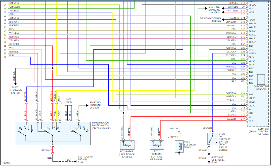
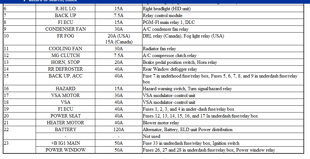
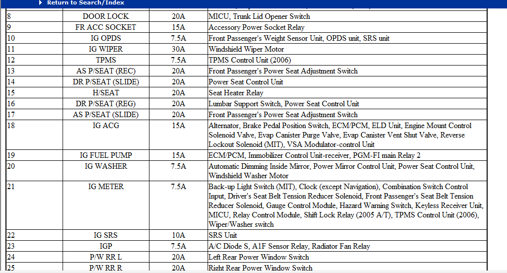
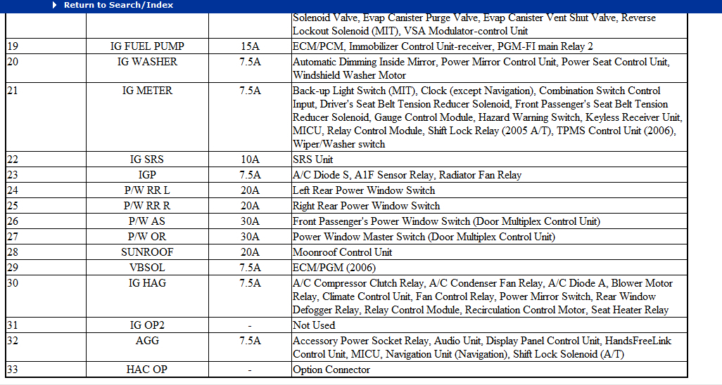
1.no main relay 2 (fuel pump relay ) just triggers the fuel pump refer to wiring diagram, fuse 19 (15A)under hood supplies positive to relay 2 pin1 and the immobilizer control unit.
check the main relay 1 which triggers the main relay 2 at pin 4.
check for positive at relay pin 1 you must get 12v from fuse 19(15A).
check pin 4 you must get 12v ignition on.
pin 2 is the positive voltage that activates the fuel pump. when the relay energized.
pin 3 is the ground that the engine control unit activates the relay2.

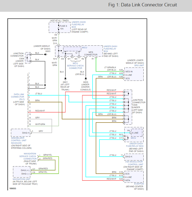
2.OBD port is not related to the relay2,check the fuse 8 (15A) which supply voltage to DLC, and relay 1.

3.yes for just testing purpose you can jump a wire between pin 1 and 2 fuel pump must be activated.

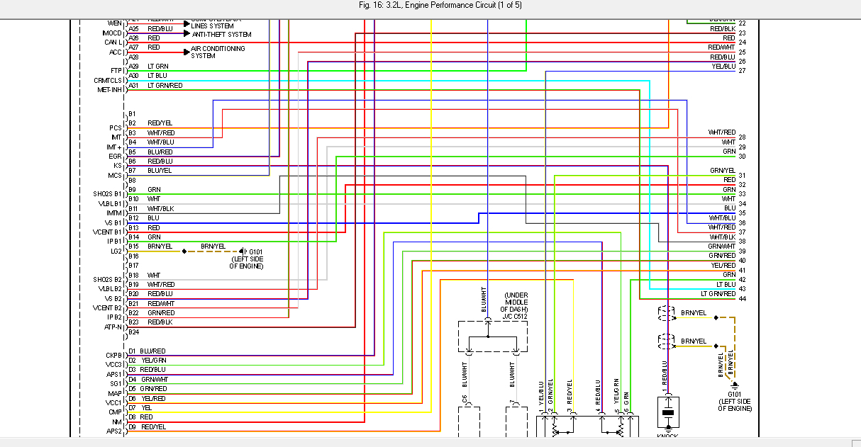
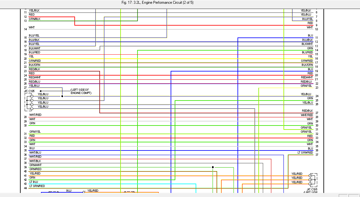
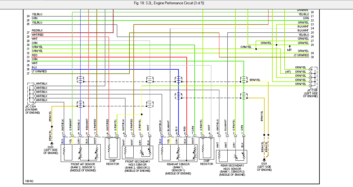
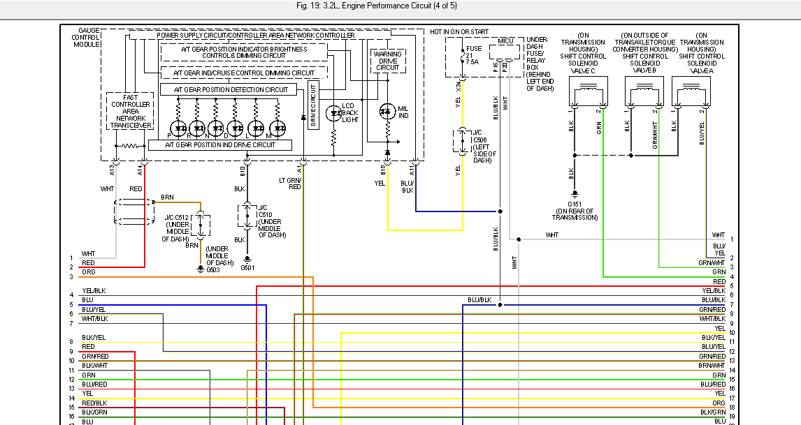
4.check the full engine wiring diagrams below which are 5 pages, each page i cutted to 3 sections for clear reading. also check the fuse box location.

please update us after the tests .

thank you.
Was this
answer
helpful?
Yes
No
Wednesday, March 10th, 2021 AT 1:52 PM (Merged)
Tiny
05ACURATL
  • MEMBER
  • 37 POSTS
Hello,

I put a tested working main relay 2 (fuel pump relay) but that didn't solve the problem. I used a jumper wire between pin 1 and 2 and was able to hear the fuel pump activate, so there doesn't seem to be a problem with the fuel pump itself. I followed the article provided above by Danny to reset the anti-theft system, however that didn't work. I keep having the flashing key (anti-theft).
I tested the 5V reference at the MAP sensor connector and it did have 5v at the yellow/red wire and 0.02V at the green/white wire (ground). So, the ECU seem to provide the proper voltages to the MAP sensor.
With regards to the OBD2 connector, I did have power at pin 16, however there is nothing at pin 14 (I tried to test voltage between pin 6 and 14).
Any idea where to take it from here? Thanks
Was this
answer
helpful?
Yes
No
Tuesday, April 13th, 2021 AT 4:46 PM
Tiny
KASEKENNY
  • MECHANIC
  • 18,907 POSTS
Let's take a step back here because I think you have a couple issues going on.

If you have a flashing key then you have an active theft system issue which is what we need to start with.

Are you able to scan for codes? I imagine not if you are saying you have DLC issues.

https://www.2carpros.com/articles/checking-a-service-engine-soon-or-check-engine-light-on-or-flashing

If you are not getting codes then you may have a ground issue with the DLC. I am not sure why you were checking voltage between 6 and 14. Take a look at the wiring diagram below. You don't have a wire in 6 but 14 is your diag high line.

6 and 14 are used in CAN bus systems but you don't have a CAN network so if you are not getting any voltage, this is why.

Let's start with this and go from there.

Thanks
Was this
answer
helpful?
Yes
No
Saturday, April 17th, 2021 AT 6:42 PM
Tiny
DANNY L
  • MECHANIC
  • 5,648 POSTS
Hello again.

I was just curious to know since you've been doing a lot of wiring testing to see if you've checked the red-blue wire from the immobilizer control unit to the ECM/PCM? I've attached the diagram below. Let us know and get back to us. Hope this helps and thanks again for using 2CarPros.

Danny-
Was this
answer
helpful?
Yes
No
Sunday, April 18th, 2021 AT 4:22 AM
Tiny
05ACURATL
  • MEMBER
  • 37 POSTS
Hi KASEKENNY1,

I used a good scanner, when I connected it it powered up then, if I remember correctly, it came back with an error saying unable to communicate with ECM/PCM. At first, I thought maybe there was no power to pin 16. So, I tested pin 16 and found that it has constant voltage. Next, I thought maybe I have a bad ECM/PCM, that's why I did the 5v reference circuit test at the MAP sensor, to make sure the computer was working.
I tried to test voltage between pin 6 and 14 because I watched a YouTube video and wanted to test the CAN bus system. I didn't know there wasn't one. I'm glad you told me there is no wire at pin 6 because it didn't seem there was one and I thought for a minute that maybe my DLC was missing wires.
It's been a while since I did the tests, but I believe grounds on pin 4 and 5 were good. I will test again pins 4 and 5 at the DLC and will get back to you with my findings. Thanks
Was this
answer
helpful?
Yes
No
Friday, April 30th, 2021 AT 12:09 AM
Tiny
05ACURATL
  • MEMBER
  • 37 POSTS
Hi Danny,

I didn't test the red/blue wire that you mentioned. What do I test for: voltage, continuity, or resistance? And what value(s) should I be looking for? Thanks
Was this
answer
helpful?
Yes
No
Friday, April 30th, 2021 AT 12:12 AM
Tiny
KASEKENNY
  • MECHANIC
  • 18,907 POSTS
Okay. Just to be clear, you want to test the voltage using a ground so I would use both pins 4 and 5 when you are testing this voltage just to be sure the supply voltage is there and the ground is good. If you have good voltage then both are good. If you do not, then you need to test each separately.

To do this, you test the supply voltage by using a known good ground like a bolt on the engine. If you have proper voltage then the supply is good.

Then test the grounds by supplying a known good 12 volts from the battery and test each pin 4 and 5 and make sure your meter reads 12 volts. If it does then the grounds are good.
Was this
answer
helpful?
Yes
No
Saturday, May 1st, 2021 AT 9:28 AM
Tiny
05ACURATL
  • MEMBER
  • 37 POSTS
Hi KASEKENNY1,

I tested pins 4 and 5 before you replied, so I didn't use the method you mentioned. As far as testing pin 16, I used a metal bracket under the dash as my ground, and I measured 12 volts at pin 16. As far as testing pins 4 and 5, I connected a test light to the positive battery post and probed each of pins 4 and 5. The test light lit up, which means there is good ground at those pins. I will measure actual voltage at pins 4 and 5 and get back to you on the readings.
As I mentioned in a previously, I tested the 5v reference circuit at the MAP sensor, but based on the wiring diagram there seem to be 3 different 5v circuits (they may be internally connected) so I will have to test the other 2 circuits to see if they are alive. I learned that a bad sensor could cause the no communication error with the scanner. So, I will try to connect the scanner with as many sensors unplugged and see if that fixes the communication problem. But other than that, do you have any more suggestions? Thanks
Was this
answer
helpful?
Yes
No
Sunday, May 2nd, 2021 AT 3:22 AM
Tiny
KASEKENNY
  • MECHANIC
  • 18,907 POSTS
Okay. Clearly those voltages and pins look good. I suspect you have a communication issue with either the circuits highlighted below or the ECM has failed.

I understand what you are saying with the 5v signal issues however, I have not seen that cause a loss of communication issue with the scan tool.

However, just because I have not seen it doesn't mean it is not possible but it would be a new one on me.

If it were me, I would check continuity and resistance of the wires below from the DLC to the ECM just to make sure there are intact.

If they are, I suspect you have an ECM issue.
Was this
answer
helpful?
Yes
No
Monday, May 3rd, 2021 AT 7:18 PM
Tiny
DANNY L
  • MECHANIC
  • 5,648 POSTS
Hello again.

We haven't heard back from you in a few days. Have you been able to test these circuits? Please keep us updated or let us know if any further information is needed. Thanks again for using 2CarPros.

Danny-
Was this
answer
helpful?
Yes
No
Wednesday, May 12th, 2021 AT 7:03 PM

Please login or register to post a reply.

Sponsored links