_______________________________________________
2007 Chevy Truck TrailBlazer 2WD L6-4.2L
P1682
Vehicle ALL Diagnostic Trouble Codes ( DTC ) Testing and Inspection P Code Charts P1682
P1682
DTC P1682
Diagnostic Instructions
Perform the Diagnostic System Check - Vehicle prior to using this diagnostic procedure. See: Vehicle > Initial Inspection and Diagnostic Overview
Review Strategy Based Diagnosis for an overview of the diagnostic approach. See: Vehicle > Initial Inspection and Diagnostic Overview
Diagnostic Procedure Instructions provides an overview of each diagnostic category. See: Vehicle > Initial Inspection and Diagnostic Overview
DTC Descriptor
DTC P1682: Ignition 1 Switch Circuit 2
Diagnostic Fault Information
pic 1
Typical Scan Tool Data
EC Ignition Relay Feedback Circuit
pic 2
Ignition 1 Signal
pic 3
Circuit/System Description
There are two ignition 1 voltage circuits supplied to the engine control module (ECM). The first ignition 1 voltage circuit is provided by the powertrain relay through a fuse. This ignition 1 voltage circuit supplies power to all the internal ECM circuits associated with the throttle actuator control (TAC) operation. The ignition main relay provides the second ignition 1 voltage circuit to the ECM through a fuse. This ignition 1 voltage provides power to other internal ECM circuits, except those associated with TAC operation. The ECM continuously monitors the voltage level difference between the 2 circuits.
Conditions for Running the DTC
The ignition is in the Unlock/Accessory, Run, or Crank position.
The powertrain relay is commanded ON.
DTC P1682 runs continuously when the above conditions are met.
Conditions for Setting the DTC
The ignition 1 voltage of the ignition main relay is more than 3 volts different than the ignition 1 voltage of the powertrain relay for more than 2 seconds.
Action Taken When the DTC Sets
DTC P1682 is a Type A DTC.
Engine may operate in a reduced engine power mode.
Conditions for Clearing the DTC
DTC P1682 is a Type A DTC.
Reference Information
Schematic Reference
Engine Controls Schematics See: Powertrain Management > Electrical
Electrical Center Identification Views See: Fuse > Application and ID
Connector End View Reference
Powertrain Control Module Connector End Views See: Engine Control Module > Connector Views
Description and Operation
Powertrain Control Module Description See: Engine Control Module > Components > Powertrain Control Module Description
Electrical Information Reference
Circuit Testing See: Vehicle > Component Tests and General Diagnostics > Circuit Testing
Connector Repairs See: Vehicle > Component Tests and General Diagnostics > Connector Repairs
Wiring Repairs See: Vehicle > Component Tests and General Diagnostics > Wiring Repairs
DTC Type Reference
Powertrain Diagnostic Trouble Code (DTC) Type Definitions
Scan Tool Reference
Scan Tool Data List for scan tool information See: Computers and Control Systems > Scan Tool Testing and Procedures > Scan Tool Data List
Circuit/System Verification
1. If DTCs P0685, P0689, or P0690 are set, diagnose those DTCs first.
2. Ignition ON, engine OFF, observe the Ignition 1 voltage signal and the EC Ignition Relay Feedback signal parameters on the scan tool. Both parameter values should display no more than 3 volts difference between the 2 parameters.
3. Ignition OFF, observe the ignition 1 voltage signal parameter on the scan tool. The parameter value should be 0 volts before the ECM powers down.
Circuit/System Testing
1. Ignition OFF, disconnect the powertrain relay.
2. Ignition ON, verify that a test lamp does not illuminate between the powertrain relay controlled output circuit terminal and ground.
- If the test lamp illuminates, test the powertrain relay controlled output circuit for a short to voltage.
3. Ignition OFF, verify that a test lamp illuminates between the powertrain relay coil voltage supply circuit terminal and ground.
- If the test lamp does not illuminate, test the powertrain relay coil voltage supply circuit for a short to ground or an open/high resistance.
4. Verify that a test lamp illuminates between the powertrain relay switch voltage supply circuit terminal and ground.
- If the test lamp does not illuminate, test the powertrain relay switch voltage supply circuit for an open/high resistance.
5. Disconnect the ECM.
6. Ignition ON, verify that a test lamp illuminates between ECM connector terminal 19 X1 and ground.
- If the test lamp does not illuminate, test the ignition 1 relay controlled output circuit for a short to ground or open/high resistance. If the circuit tests normal and its fuse is open, replace the ECM.
7. Ignition OFF, connect the harness connector at the ECM.
8. Ignition ON, connect a jumper wire between the powertrain relay voltage supply circuit terminal and the powertrain relay controlled output circuit terminal. Verify the EC Ignition Relay Feedback parameter indicates battery positive voltage.
- If not the specified value, test the powertrain relay controlled output circuit for a short to ground or an open/high resistance. If the circuit tests normal and its fuse is open, replace the ECM.
9. If all circuits test normal, replace the powertrain relay.
Repair Instructions
Perform the Diagnostic Repair Verification after completing the diagnostic procedure. See: A L L Diagnostic Trouble Codes ( DTC ) > Verification Tests
Relay Replacement See: Vehicle > Removal and Replacement
Control Module References for ECM replacement, setup, and programming See: Vehicle > Programming and Relearning > Control Module References
__________________________________________________________________
2007 Chevy Truck TrailBlazer 2WD L6-4.2L
P1516
Vehicle ALL Diagnostic Trouble Codes ( DTC ) Testing and Inspection P Code Charts P1516
P1516
DTC P1516
Circuit Description
The commanded throttle position is compared to the actual throttle position based on accelerator pedal position (APP) and possibly other limiting factors. Both values should be within a calibrated range of each other. The powertrain control module (PCM) continuously monitors the commanded and actual throttle positions. This DTC sets if the values are greater than the calibrated range.
DTC Descriptor
This diagnostic procedure supports the following DTC:
DTC P1516 Throttle Actuator Control (TAC) Module Throttle Actuator Position Performance
Conditions for Running the DTC
* The ignition is ON.
* The ignition voltage is greater than 8 volts.
* The system is not in the battery save mode.
* The engine is running.
* DTC P0068 is not set.
* DTC P1516 runs continuously when the above conditions are met.
Conditions for Setting the DTC
* The difference between the predicted and the actual throttle position is more than a calibrated amount.
* The above condition is present for more than 0.5 second.
Action Taken When the DTC Sets
* The control module illuminates the malfunction indicator lamp (MIL) when the diagnostic runs and fails.
* The control module records the operating conditions at the time the diagnostic fails. The control module stores this information in the Freeze Frame and/or the Failure Records.
* The control module commands the TAC system to operate in the Reduced Engine Power mode.
* A message center or an indicator displays Reduced Engine Power.
* Under certain conditions the control module commands the engine OFF.
Conditions for Clearing the MIL/DTC
* The PCM turns OFF the MIL after 3 consecutive drive trips that the diagnostic runs and passes.
* A History DTC clears after 40 consecutive warm-up cycles in which there are no failures reported of this diagnostic or any other emission related diagnostic.
* The scan tool clears the MIL/DTC.
Diagnostic Aids
The throttle valve is spring loaded to a slightly open position. The throttle valve should be open approximately 20 percent. This is referred to as the rest position. The throttle valve should not be completely closed nor should they be open any more than the specified amount. The throttle valve should move open and to the closed position without binding under the normal spring pressure. The throttle should NOT be free to move open or closed WITHOUT spring pressure. Replace the throttle body if any of these conditions are found.
Important: Operating the throttle blade with the Throttle Blade Control function of the scan tool may cause additional DTCs to set. Do not attempt to diagnose DTCs set during this function.
The scan tool has the ability to operate the throttle control system using Special Functions. Actuate the throttle valve using the throttle blade control function located in the Throttle Actuator Control (TAC) System menu. This function will operate the throttle valve through the entire range in order to determine if the throttle body and system operate correctly.
Check for the following conditions:
* Use the J35616 Connector Test Adapter Kit for any test that requires probing the PCM harness connector or a component harness connector.
* Poor connections at the PCM or at the component-Inspect the harness connectors for a poor terminal to wire connection. Refer to Testing for Intermittent Conditions and Poor Connections for the proper procedure. See: Vehicle > Component Tests and General Diagnostics
* For intermittents, refer to Intermittent Conditions. See: Computers and Control Systems > Initial Inspection and Diagnostic Overview > Intermittent Conditions
Test Description
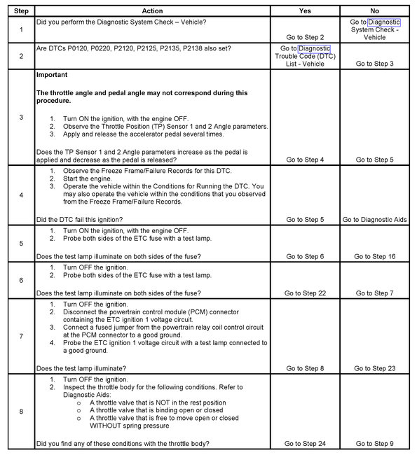
Step 1 - Step 8
pic 4
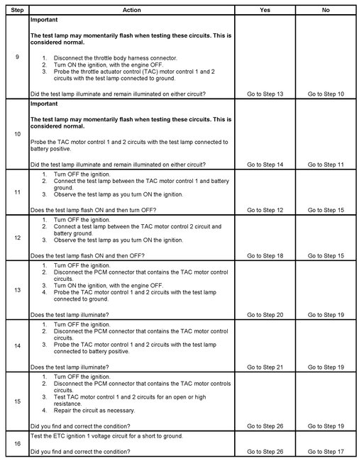
Step 9 - Step 16
pic 5
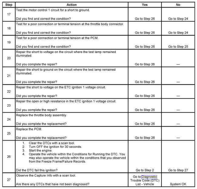
Step 17 - Step 27
pic 6
The numbers below refer to the step numbers on the diagnostic table.
8. The throttle valve is spring loaded in a slightly open position and should move in either direction without binding. The throttle valve should always be under spring pressure.
11. When the ignition is turned ON, the PCM operates the throttle control motor to verify the integrity of the system prior to start-up. This can be seen by the momentary flash of the test lamp as the ignition is turned ON.
___________________
Let me know what you find.
Joe
Was this helpful?
Yes
No
Sunday, January 5th, 2020 AT 7:04 PM


