I listed all of the conditions for the codes you listed. The one thing I doubt you have done is the crank relearn, but the engine needs to be running properly to do it. I added it at the end.
The majority of the things listed deal with the ignition 1 circuit. I'm not gong to lie when I say, I believe you checked all these things. Take a look.
DTC P0315 Crankshaft Position (CKP) System Variation Not Learned
DTC P1516 The commanded throttle position is compared to the actual throttle position based on accelerator pedal position (APP) and possibly other limiting factors. Both values should be within a calibrated range of each other. The powertrain control module (PCM) continuously monitors the commanded and actual throttle positions. This DTC sets if the values are greater than the calibrated range.
DTC 1682 There are two ignition 1 voltage circuits supplied to the engine control module (ECM). The first ignition 1 voltage circuit is provided by the powertrain relay through a fuse. This ignition 1 voltage circuit supplies power to all the internal ECM circuits associated with the throttle actuator control (TAC) operation. The ignition main relay provides the second ignition 1 voltage circuit to the ECM through a fuse. This ignition 1 voltage provides power to other internal ECM circuits, except those associated with TAC operation. The ECM continuously monitors the voltage level difference between the 2 circuits.
DTC P0030 / P0036 Conditions for Running the DTC
* The Ignition 1 Signal parameter is between 11-18 volts.
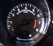
* The Engine Speed is more than 425 RPM.
* DTC P0030 and P0036 run continuously once the above conditions are met for 1 second.
Conditions for Setting the DTC
* The PCM detects that the affected HO2S heater low control circuit is not within a specified range.
* DTCs P0030 and P0036 set within 3 seconds once the above condition is met.
DTC 0102 Circuit/System Description
The mass air flow (MAF) sensor is integrated with the intake air temperature (IAT) sensor. The MAF sensor is an air flow meter that measures the amount of air entering the engine. The powertrain control module (PCM) uses the MAF sensor signal to provide the correct fuel delivery for all engine speeds and loads. A small quantity of air entering the engine indicates a deceleration or idle condition. A large quantity of air entering the engine indicates an acceleration or high load condition. The MAF/IAT sensor has the following circuits:
* An ignition 1 voltage circuit
* A ground circuit
* A MAF sensor signal circuit
* An IAT sensor signal circuit
* A low reference circuit
The PCM applies 5 volts to the MAF sensor on the MAF sensor signal circuit. The sensor uses the voltage to produce a frequency signal based on the inlet air flow through the sensor bore. The frequency signal varies in a range of near 1,500 Hertz at idle to near 9,500 Hertz at maximum engine load. The PCM converts the Hertz input signal to a grams per second (g/s) value. This value is displayed on the scan tool as the MAF Sensor g/s parameter.
Conditions for Running the DTC
* The engine is running for greater than 5 seconds.
* The engine speed is greater than 300 RPM.
* The ignition 1 signal is between 11-18 volts.
* The above conditions are met for more than 0.5 second.
* This DTC runs continuously within the enabling conditions.
Conditions for Setting the DTC
DTC P0102
The PCM detects that the MAF Sensor parameter is less than 2 g/s for greater than 3 seconds. This is equivalent to less than 100 Hz. For greater than 3 seconds.
DTC 2101 DTC Descriptor
This diagnostic procedure supports the following DTC:
DTC P2101 Throttle Actuator Position Performance
Conditions for Running the DTC
* The ignition is ON.
* The ignition voltage is greater than 8 volts.
* The system is not in battery saver mode.
* The engine is running.
* DTC P0068 is not set.
* DTC P2101 runs continuously when the above conditions are met.
Conditions for Setting the DTC
* The difference between the predicted and the actual TP is more than a calibrated amount.
* The above condition is present for more than 0.6 second.
Action Taken When the DTC Sets
* The control module illuminates the malfunction indicator lamp (MIL) when the diagnostic runs and fails.
* The control module records the operating conditions at the time the diagnostic fails. The control module stores this information in the Freeze Frame and/or the Failure Records.
* The control module commands the TAC system to operate in the Reduced Engine Power mode.
* A message center or an indicator displays Reduced Engine Power.
* Under certain conditions the control module commands the engine off.
____________________
Here are the relearn procedures for the crank sensor, but the vehicle needs to be running properly for it to happen.
Joe
Thursday, January 16th, 2020 AT 4:39 PM