Voltage keeps raising on signal wire of TPS sensor

Tiny
CARADIODOC
  • MECHANIC
  • 33,742 POSTS
I agree grounds don't seem to be the problem.

When the IAC counts are high, the computer is requesting an increased engine speed. The only things I can think of are that's in response to a cold engine or cold intake air, or it's because the computer is expecting the engine to be loaded down by the AC compressor cycling on or the generator putting a high load on the engine to run the rear defroster. Most commonly I'd expect to see an incorrect reading from one of the temperature sensors.

I'm going to get another one of our experts involved to see if we can figure this out.
Was this
answer
helpful?
Yes
No
Sunday, November 15th, 2020 AT 5:06 PM
Tiny
FIXTHISONE
  • MEMBER
  • 34 POSTS
Thank you for your follow up.
I agree that the temperature input or any other demand from a sensor may increase the RPM a bit. A/C load or extra electrical demand for headlights and rear defroster, in my opinion could never cause a engine to hit 3400 RPM and nothing that I did brought the RPM down. At that time I didn't know or considered the " re-learn" approach by turning the engine off and playing with KOEOFF scenario, nor did I have the IAC controller.

I'm leaning towards something in the IAC circuit, because the RPM will respond directly to the "controller". I unplug the sensor and plug in the controller and from there is just a matter of commanding the RPM up or down and I can see it on the Tech II as it changes.

One thing that continues to baffle me. The TPS voltage and % being displayed are wrong.
I don't know if mentioned but the horn circuit seems to be in short. If I put in the fuse the horn blows. I wonder if this may have something to do with the problem. A shorted wire contacting a sensor lead.
Ever since I bought the car the horn problem and the cluster panel had problems. I can't see the selected gear or the odometer on the dash.
I even had a funny event, about this. My wife wanted to move the car off the driveway so the grass could be cut. She started the car and drove forward on to the street, the car was having one of these "high RPM attacks" by the time she sort of controlled it, it was halfway on the street, she wanted to bring it back but couldn't find reverse. Every time she let go of the brake, the car would just move farther, my wife and my daughter didn't know what to do, eventually they just drove around the corner and then parked on the side. Needless to say, they told me what a great car I had bought, something that can't even display the gear selected.
I can see the gear selection on the Tech II( I don't think it will go well with the wife if I suggest to use the scanner to figure out which gear is selected.)
The reasons that I haven't gone into the dash board and the horn, are; first that dealing with the SRS is explosive and second if I can't fix the car I would be putting quite a bit of time into pulling the dash out.
So the idea is to repair the high RPM problem and then fix the rest.
I can't imagine that I won't be able to resolve this matter, it can't possible be that complicated if the right information is available. I will keep searching and with your help I know that we will overcome this problem.
Thank you for all your assistance.
Was this
answer
helpful?
Yes
No
Sunday, November 15th, 2020 AT 6:26 PM
Tiny
CARADIODOC
  • MECHANIC
  • 33,742 POSTS
I pounded off a message to "Steve W" last night. I got a reply tonight that he is going to need some time to read through everything before he can come up with some ideas of value.

In the meantime, I'm going to add a comment about the automatic idle speed motors, (aka idle air control) Ford used a two-wire solenoid that pulled the spring-loaded air bypass valve open more and more in relation to the voltage applied to it by the computer. A lot of people assume all cars work that way. In fact, Ford is the only manufacturer I'm aware of that does that. GM and Chrysler use the same four-wire idle speed motor. They just call them different names "AIS" and "IAC" are the same thing. This is a "stepper" motor with a pintle valve on the end of a threaded shaft hooked to the motor's armature. This motor doesn't have brushes and it doesn't spin like a regular motor. Instead, it has four coils of wire connected to those four terminals, to make four electromagnets. The computer pulses those coils with varying voltages and polarities, then the armature follows those rotating magnetic fields around. Each time a coil is pulsed, the armature could rotate just a fraction of a revolution. 256 steps or counts takes it from fully-closed to fully-open.

As the armature rotates, that treaded shaft extends or retracts the pintle valve to adjust how much air can sneak past the throttle blade. At the same time it adjusts how long it holds the injectors open when it pulses them, thereby adjusting fuel volume. Air and fuel together adjusts idle speed.

The point of interest here is unlike the Ford system, if you were to unplug the AIS motor, or if one of the wires were cut, or if one of the four driver circuits in the computer was defective, the motor would not turn at all. The pintle valve would stay right where it is at that time, and at most, it might twitch a little.

Your controller is designed to develop those same pulses of voltage in sequence to cause the motor to rotate. That alone proves the motor is working. If you see idle speed changing along with the counts, or steps, on the scanner, that also proves the motor along with the four wires and four driver circuits are okay. That is all considered an output circuit for the computer. It is able to control the motor. We need to look at the inputs to the computer to figure out why it is erroneously asking for a higher idle speed. I hope Steve will have some answers or some insight on where to go next.

For your horn, the best suspect is a shorted clock spring. Pull the horn relay out, then pop the fuse back in. If the horns are easy to reach, unplug them. Now, when you start to reinsert the relay, chances are you'll feel it click. In the unlikely event it doesn't click, and the horns turn on when you plug one back in, that relay is shorted, as in the contacts are welded together. That doesn't happen very often, and on older cars it never happened because they used a special sliding contact design to prevent that.

We really should start a new question for the horn. The site is set up to organize topics and car models in a way others researching the same problem can find these posts. Someone working on a similar car with a horn problem won't find this in any index when it's added on to the idle speed topic.

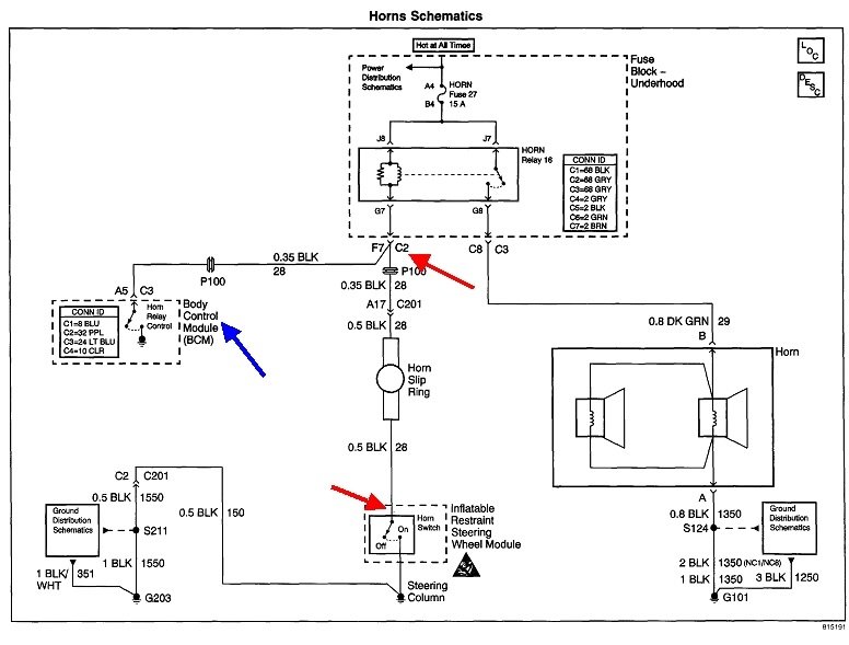
Regardless, here's the horn diagram to get you started. If the car has a factory anti-theft system, the Body Computer, (blue arrow), can ground the coil for the horn relay to chirp the horn. That driver circuit could be shorted. The fastest test would be to unplug that computer and see if the horn relay clicks off.

They show the horn switch circuit between the two red arrows as having a slip ring. That was what all cars used before air bags came along. Any small spots of dirt or dried grease could cause an intermittent connection for the horn switch, but only until the steering wheel was turned slightly. Even normal vibration with the engine running is enough to make a sufficient contact for the relay to turn on.

They can't rely on that sliding contact for an air bag. Those are timed to the millisecond to deploy at the proper time. To insure there's a solid connection, they use a wound-up ribbon cable inside a plastic housing, under the steering wheel. Since that cable is already there, it's a simple matter to add a few additional circuits for cruise control switches and the horn. It's not that uncommon for some of those circuits to unravel and touch each other. Those would be on the diagram where they show the slip ring. Anything shorted to ground between the two red arrows will turn the horn relay on.

Normally air bags are very safe to work on, but the one thing that worries me is when the clock spring is coming apart. For demonstration purposes, an air bag can be fired with a little 9-volt transistor battery, so it doesn't take much. Static electricity can do it too, but that threat is eliminated when any bright yellow connector is unplugged. The air bag side of the connector will have a shorting bar inside it to prevent accidental deployment when the bag is being handled. Those shorting bars are pushed out of the way when the plugs are connected. That leaves it vulnerable to static discharge when the clock spring comes apart. A quick test to put your mind at ease is to observe the red "Air Bag" light turns on for six seconds when you turn on the ignition switch, then it turns off and stays off. That is the self-test period where a defect in that part of the clock spring would be detected. If there's no defect in that part, the air bag system is safe to work on.

Normally when clock springs fail, the ribbon cable snaps off on one end. The most common list of symptoms is the cruise control and horn don't work, and the "Air Bag" warning light stays on. Often these three systems fail a few days apart.

I'll go into more detail later if necessary, but for now, just be aware when you replace a clock spring, it can only rotate just slightly more than the steering system from full-left to full-right. It has to be centered, otherwise it will wind up too tight when turning one way and the cable will snap instantly, or it will unwind too far the other way and fold over on itself. That will also cause it to break on one end, but it will take some time.

Here's links to articles related to clock springs:

https://www.2carpros.com/articles/symptoms-of-a-bad-airbag-clock-spring

https://www.2carpros.com/articles/steering-wheel-clock-spring-removal

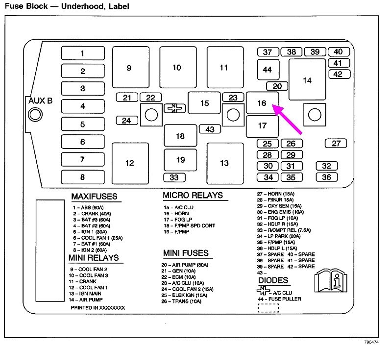
The second drawing shows the horn relay in the under-hood fuse box.
Was this
answer
helpful?
Yes
No
Monday, November 16th, 2020 AT 8:11 PM
Tiny
CARADIODOC
  • MECHANIC
  • 33,742 POSTS
Ken had mentioned early on that he suspected the Engine Computer. Today I got a reply from Steve W. Also suspecting the computer. He brought another friend into the conversation who suggested removing a wire from splice # 205 to see if that affected the TPS voltage, but I haven't found that yet on the diagrams.

I'm always afraid to condemn the computer because my experience has been mostly with Chrysler's, and those had very little trouble. GM had a lot of Engine Computer trouble in the late '80s to md '90s, and that left a lot of people falling on the computer as the first suspect ever since instead of ruling out everything else first. There's no denying replacement computers solve a lot of problems, but I tend to have to see it first before I believe it. That's the only thing I can think of that would command a high engine speed when all the other sensors appear to be working correctly.
Was this
answer
helpful?
Yes
No
Wednesday, November 18th, 2020 AT 5:21 PM
Tiny
FIXTHISONE
  • MEMBER
  • 34 POSTS
Good morning and thank you again for all your efforts in helping me out with this problem.
There is a person that goes under the "nom de guerre" Scanner Danner, he has videos on YouTube, a paid channel, a book and I understand he is also a teacher in an automotive trade school. Way back he called that the PCM is very likely to be the one, you brought out the same thing, and additionally I consulted with an additional party. Quite a few are leaning that way.
At this point I'm going to pull out the PCM and take it to a facility that they can check it and let me know if this is indeed the problem.
I sensed that there is some hesitation to choose the "death penalty" option, everyone seem to try to rule out everything else, which is an exhaustive process.
I wonder how hard is it for someone to come up with a quick test that could id the PCM as the problem. I would think that there has to be a way to perform some check with an outside device on the PCM, and establish whether it is a go or no go.
The next question would be" why did it fail?", I think that is the reason that people don't just replace the PCM, because if one calls it bad and then installs a new one and it immediately fails, it will not look good. Prices, for PCM's" aren't as high as they use to be, but can't be considered inexpensive either.
I'm going to go out to the car and do some final test for grounds and then pull out the PCM.
At that point I will analyze my options and take the next step.
Thank you for all the information that you sent me on the horn condition. I didn't mean to "muddle the water" I put that in there as background information, just in case someone knew about some "screwy" condition where the instrument panel or the horn circuit could interfere with another circuit and would create the condition that I'm experiencing.
I will let you know what is the outcome.
Thanks
Was this
answer
helpful?
Yes
No
Thursday, November 19th, 2020 AT 6:52 AM
Tiny
FIXTHISONE
  • MEMBER
  • 34 POSTS
Latest events on this complex saga. I removed the PCM because I'm considering replacing the unit. I have run into a variety of explanations and some high prices in comparison to one major supplier, which makes somewhat confusing as to what each one is actually offering.
I had to move the vehicle and therefore put the old PCM back on.
Starting was normal and RMP came down.
I turned the headlight on and there was a surge in RPM, ( maybe a couple of minutes) I played with the switch and then RPM's came down.
Ran the car for about 35 minutes and everything was fine despite, TPS being way off, IAC was normal, RPM's were normal.
I poked, shook, rattled, tapped, all the sensors, and wiring harnesses that I could access. I could not see any change in the parameters displayed on the scanner.
So here is the question:
How can I have spells of normalcy and in other occasions, huge RPM spikes?
There is no reason or rhyme to this intermittent event event and I have not been able to duplicate the high RPM's spikes.
Truly confused by these events, but I will continue to look for the reason.
Thank for all the help so far.
Was this
answer
helpful?
Yes
No
Thursday, November 19th, 2020 AT 3:51 PM
Tiny
CARADIODOC
  • MECHANIC
  • 33,742 POSTS
Twenty years ago I was invited by the owner of the company to visit Downtown Radio of Denver. They were one of three authorized warranty repair centers for Chrysler and GM car radios, and they repaired digital instrument clusters. As a hobbyist and tv repairman, we do things quite differently. We diagnose down to the component level, meaning the failed transistor or resistor, repair that, then try to figure out why it failed and if there's anything we can do to prevent it from happening again. Testing consists of letting the product run on the test bench for a few hours.

The repair center takes a different approach. They don't have time to diagnose and repair each item. They just pop in a new circuit board, then the product goes through hours of heat and vibration testing. If it passes, each one gets a new faceplate, then it's shipped out as a warranty replacement. They spend way more time on testing, but that new board they put in was likely built at the same time as all those others that are developing problems. For example, I ran into hundreds of one radio model that would develop one of four problems, all related to four transistors that were high-failure items. I replaced all four of them on every radio I got in for repair. If a new board was installed at the authorized repair center, were they being supplied the same boards with the high-failure transistors, or were they getting upgraded boards? Also, as far as I'm concerned, throwing away an expensive board that could be repaired with less than a dollar's worth of parts, and an hour of time was a better choice.

The point is, those professionals put a lot more emphasis on testing to insure you get a properly-working product. Testing a car radio consists of pushing a dozen buttons, and looking for good sound quality and system operation. Engine Computers can have over 100 wires, and many dozens of input and output circuits that all have to operate in relation to each other. It is not practical for a person to manually connect an intake air temperature sensor to see if it reads correctly, then see if it still does so when the radiator fan relay is commanded on, and then when the computer gets an input pulse from the crankshaft position sensor. Even if it were practical to do that, it is just one set of three variables when there are dozens of variables to consider that make up an infinite number of combinations.

This reminds me of a local race car manufacturer that used to be in my city. We also had a local short-track champion who was one week away from going to Nascar before he was involved in a tragic crash. Every once in a while, the car manufacturer would get a call from a customer who was having a specific handling problem at one race track. The owner would come to the shop of the local driver and set his car up the same way, then, out on the local track, he would use race night to experiment with different adjustments, then contact the customer with suggestions. The variables he looked at included, tire sizes and differences side-to-side, tire pressures, degree of banking on a certain corner, track and air temperature, humidity, weight distribution, alignment angles, pretension on the two anti-sway bars, and numerous other things.

One day that guy showed up while I was visiting the shop, and said, I guess we'll set it up to be a race winner tomorrow night. He wasn't kidding. Most of his work involved adjusting the anti-sway bars. The next night that car won its heat race and the feature race. Not even Dick Trickle could keep up to him.

The point of that sad story is they had to know what all the variables were, and how they interacted with each other. There are a lot of places you can send an Engine Computer to for repair, but do they diagnose each one individually like I did with car radios, and do they verify proper operation while manipulating all those variables?

You also were wondering how these failures occur? I mentioned component failures like transistors that aren't beefy enough. Let me make a side note for a minute. When transistors are manufactured, they go through all kinds of tests to include vibration, humidity, frequency response, and adherence to design specifications. If a transistor passes every test, it's good for military use. If it's almost as good but maybe falls short in one or two areas, it's still good enough for our cars and home computers. It can fail many more tests but still be good enough for consumer products. If it fails almost every test, but is otherwise still a working transistor, it gets packaged up with a bunch more like it, and they're sold to hobby shops and the likes of Radio Shack. Car manufacturers pay a lot more for an electronic part than you can buy a replacement for, simply because of the rigorous testing. That doesn't mean one won't fail though.

In its most basic form, think of a transistor as a two-terminal switch, and current through it is turned on and off according to the voltage applied to its third terminal. It could develop high resistance so it doesn't let full current flow through it when turned on. It could become shorted, so it's always conducting current, even when we don't want it to. Halfway in between, it could become "leaky", meaning a little current gets through when it shouldn't. That is often aggravated by heat. Current flow through the transistor creates heat, and heat is the deadly enemy of transistors. The most common place to hear the results of leakage is in the background static in your home stereo speakers. That can become very loud, with popping and sizzling sounds. We often identify the culprit by spraying it with "Freeze Mist" from a spray can, to cool the part.

Now consider there are thousands of transistors built into integrated circuits, and every computer has at least one microprocessor, and those can easily have millions of transistors inside. Every one of them has to work perfectly all the time. This makes my head spin, and it's why I prefer to drive older vehicles.

There's many capacitors and resistors in every computer module. Those have their own ways of failing. There's also many heavy transformers that are usually just held in place by their terminals that are soldered to the circuit board. With constant vibration, it's a wonder more of them don't develop broken solder connections. Vibration and temperature changes can cause a bad connection to work at times and fail at other times. All of these things, from leaky transistors, to poor solder connections, can cause intermittent problems. If those defects don't cause a problem while the computer is being tested, the technician won't have any way of knowing that potential problem exists. It could be up to the person who receives it to discover the intermittent problem after he went through all the work of replacing it. That's why the better repair shops provide a warranty on their products.

Be aware too that GM is not in the business of repairing computers. When you order a rebuilt computer through the dealer, it might actually come from one of their authorized repair centers, or it could have come from that repair center, to GM, and then through their shipping channels to the dealer. When you deal with a repair company, you might be working with the same company that does the repairs for GM. One that I'm aware of is United Radio in Syracuse, NY. Another used to be Instrument Sales and Service in Kent, WA. I never dealt with them.

This is where it would be better if they just popped in an entire new circuit board. I don't know how to tell if that was done, except it would most likely be more expensive than just replacing a few parts on a used board. I can share that with Chrysler computers and other electronics, their part numbers end with "-AA" at first. If a revision is done, either at the factory or after it has been removed from a customer's car, it will be labeled "-AB". I've seen radios as high as the suffix, "J".

When a computer gets a major revision that might even include an entirely new board in the old housing, it gets a new part number. That could be on a preprinted sticker, or it could be hand-written on a generic sticker. This is why, at least with Chrysler products, when looking for a computer or other electronic module in a salvage yard, go by the application, not the part number. If the part number is the same as on your old part, they are the same. If the numbers are different, that replacement part could still work in your vehicle. It's just an upgraded part. I'm sure GM has a similar way to read their part numbers. The people at most salvage yards should be able to help with deciphering those numbers.
Was this
answer
helpful?
Yes
No
Thursday, November 19th, 2020 AT 5:58 PM
Tiny
FIXTHISONE
  • MEMBER
  • 34 POSTS
Hello,

It looks like I may have finally resolved the PCM issue.
After I considered the available options for a replacement PCM, I decided to go with a seller on eBay.
I received the module yesterday and was able to install it today.

Some additional comments about my replacement process are:

I re-routed a wire, from a repair by the previous owner, that I felt was too close to the spark plugs wires. The wire actually broke and I repaired it with solder and shrink tube.
I also laid a bare copper wire to ground stray voltage from the spark plug wires.
I don't know if it makes sense or not, but looks like there has been a previous PCM repair, so I don't want to be doing this again.
As of now I have run the car for two cycles ( 01h34m and 26 minutes) and everything is perfect. I will monitor it for the next week and hopefully all will be well.
Your suggestion for the Tech II proved extremely valuable in analyzing the car's condition. I would never been able to arrive at that decision without your input.

At this time I want to extend my to you my sincere thanks for all the patience that you had in explaining many intricate details.
I can say that today I have a much deeper understanding of the electrical/electronics parts of an automobile and this is in great part to the knowledge that you presented to me.

I wish you lots of health, wealth and luck on your future endeavors.
Thank you for everything.
Was this
answer
helpful?
Yes
No
Tuesday, December 1st, 2020 AT 8:01 PM
Tiny
CARADIODOC
  • MECHANIC
  • 33,742 POSTS
Dandy. Happy to hear of your progress. I'm embarrassed to say I forgot something that is fairly common on GM vehicles, but your wire routing observations reminded me of this. Due to their design, starting with the redesigned generators in 1987 models, they develop a real lot of voltage spikes that can destroy the generator's diodes and internal voltage regulator, and interfere with computer sensor signals. The battery is the key component that dampens and absorbs those harmful spikes, but as they age and the lead flakes off the plates, the battery loses its ability to do that. It is not uncommon to go through four to six generators in the life of the vehicle. To reduce that number of repeat failures, always replace the battery at the same time that you have to replace the generator, unless it is less than about two years old.

To tell if the voltage spikes are causing an engine performance or running problem, unplug the small connector at the rear / side of the generator. The battery will stop being charged, but you'll be able to take a short test-drive, long enough to see if the symptoms subside. If the engine runs better, try a different, (newer) battery. If that doesn't help, have the generator tested for "ripple" voltage. That is usually just shown on the tester as "low" or "high" on a relative bar chart. If it's high, there's a defective diode in the generator. Most diode failures are caused by voltage spikes, and one defective diode, of the six, causes increased voltage spikes.

In many applications you can do a simple test for ripple voltage yourself with a digital voltmeter. Switch it to "AC Volts" on a low range, typically 20 volts, then measure the battery's voltage while the engine is running. I use a professional load tester that shows relative ripple voltage, so I don't have a good feel of what's a normal or high AC voltage. One problem with this test is it basically just shows if there's "some" or "none" ripple voltage. Digital voltmeters are designed and calibrated to read a 60-cycle sine wave on "AC Volts", as would be found in your house. Automotive generators put out three phase output which triples its frequency beyond what is already a lot higher than 60 cycles per second, even at idle, plus, it's not a nice clean sine wave.

Here's some drawings I put together a while ago. The first one shows the output of each of the three phases, for half of a cycle. When one phase has gone past its highest output and is on the way down, a different phase is coming up on its maximum output. Think of a three-cylinder engine with three equally-spaced power pulses. It would feel fairly smooth.

The second drawing shows a missing phase due to a failed diode. This would be like feeling one misfiring cylinder on a three-cylinder engine. You'd definitely know it.

In both drawings, the red lines show the actual voltage being developed by the generator. It has to be higher than battery voltage to force electrons to go into the battery to be stored there. This is the ripple voltage. In the first drawing, it's only half a volt. That is real easy for the battery to smooth out. As I drew it in the second drawing, with one missing phase, ripple voltage is 5.2 volts. That is almost impossible for the battery to clean up. On older cars that would be heard as a loud whining noise on AM radio. The only other symptom is under a full-load output test, the generator would only be able to develop exactly one third of its rated current. 20 - 25 amps from the common 65-amp generator could have been enough to meet the demands of the electrical system and keep the battery charged, but not on newer cars with all their computers and electrical systems.

This ripple voltage with the red lines is what the professional load testers measure, and is more accurate than what you'd see with a digital voltmeter.

This is still different than the voltage spikes I described. Voltage spikes due to an old battery can result in a failed diode, and therefore high ripple voltage. High ripple voltage may not cause computer problems, but it can lead to increased voltage spikes. Either one can cause the other, but it's those voltage spikes that interfere with sensor signals.

Any time current flows through a wire, it sets up a magnetic field around that wire. Any time a magnetic field grows or shrinks past a wire, (it's moving), it "induces" a voltage in that wire which causes current to flow in it. That's how ignition coils work. The secret is the magnetic field has to be moving in relation to the wire. (That's why we have to spin the generator's electromagnet with a belt and pulley). If you were to get a nice steady current flow from the generator to the battery, even though there would be a huge magnetic field around that wire, it wouldn't be changing, therefore, it's not moving in relation to all the other wires next to it in that harness. It's when you have the high ripple voltage or the voltage spike, that you get a pulsing or moving magnetic field. That is what induces corresponding pulses in all the other nearby wires. That could change a sensor's readings by tenths of a volt. In the case of MAP sensors on Chryslers, and mass air flow sensors on all other brands, those have the biggest say in fuel metering calculations. A change in a few hundredths of a volt means a lot to the computer, so it's easy to see how induced voltages from excessive ripple or voltage spikes can affect how the engine runs. When you unplug the small connector on the generator, there's no more electromagnet inside it, and no more output current. No more voltage spikes will be induced in the sensors' or other wires, and the engine performance symptoms would clear up.
Was this
answer
helpful?
Yes
No
Tuesday, December 1st, 2020 AT 9:42 PM

Please login or register to post a reply.

Sponsored links