Voltage keeps raising on signal wire of TPS sensor

Tiny
FIXTHISONE
  • MEMBER
  • 2002 BUICK CENTURY
  • 3.1L
  • V6
  • 2WD
  • AUTOMATIC
  • 150,000 MILES
Parameters:
Engine cold
KOEO condition
TPS connector is unplugged.
Voltage measurements are being taken at the connector end and reader is plugged at OBD port under dash.
Reference wire voltage 5V
Ground 0V
Signal wire. Voltage starts around 0.8 V and slowing keeps going up.
No movement of throttle.
DTC reader keeps reading increased % of throttle.
turn ignition off Voltage reading goes to 0 volts.
Could this be a short to voltage? Or is the PCM defective.
At least I can now duplicate the conditions in a constant manner.
Key on and the voltage starts to go up, key off voltage drops to zero.
Any suggestions as to what is causing this condition, that causes the voltage to increase slowly. After a few minutes the reader was showing around 43% throttle open when the throttle wasn't open at all ( should show 0%).
Thank you
Tuesday, September 29th, 2020 AT 2:23 PM

49 Replies

Tiny
CARADIODOC
  • MECHANIC
  • 33,752 POSTS
The voltage readings are meaningless if you have the TPS unplugged. That would be like saying you have good water pressure in your shower because it reads normal with the valve turned off and no water flowing. You have to measure water pressure when the faucet is turned on. If the pipe is 99 percent blocked with rust, you will still read full pressure until you turn the faucet on, then it will drop to almost nothing.

Voltage is electrical pressure, and it works the same way as water pressure in a pipe. Once the TPS is plugged in, you'll still find the 5.0-volt supply on one wire, expect to find 0.2 volts on the ground wire, then the center wire / movable contact inside the TPS will read roughly 0.5 volt at idle to roughly 4.5 volts at wide-open-throttle.

What is unusual is you're finding the signal wire's voltage goes up so slowly. It should jump to 5.0 volts instantly as soon as the sensor is unplugged. At first, logic would dictate you'd find 0.0 volts when it's unplugged, but in fact, because of all the interconnected circuitry inside the Engine Computer, the actual voltage is going to "float" to some random value. If that value were to fall within the acceptable range of 0.5 to 4.5 volts, the computer will accept it as normal, and try to run the engine on that. To prevent that, all manufacturers use either a "pull-up" resistor or a "pull-down" resistor on all sensor circuits to force the signal voltage to go to a defective state so it will get detected as defective by the computer, and it will set the appropriate fault code to direct you to the circuit that needs further diagnosis.

Those resistors are so huge electrically that under normal operation, they have no effect, and it's like they aren't even there. When the sensor is unplugged, a pull-up resistor is connected between the signal wire and the 5.0-volt supply, so it puts 5.0 volts on the signal wire. The TPS has mechanical stops inside it that limit its travel to 0.5 to 4.5 volts. (Those voltages are for training and explanation purposes. In actual practice, you might find 0.62 to 4.23 volts, or something similar. The actual values aren't important. What is important is the signal voltage on most sensors can't reach 0.0 or 5.0 volts. They can only reach those voltages when there's a defect in the circuit).

Similarly, when they use a pull-down resistor, those are connected between the signal wire and ground. When that sensor is unplugged, you'll find 0.0 volts on the signal wire.

You didn't list the symptoms or problems you're trying to solve. We commonly check the voltages you already have taken, but then we get confused and stop there when things don't make sense. That is usually when the one last defect is finally discovered. That is a break in the signal wire. That can include a broken wire, but more commonly a corroded pair of mating terminals in the connector for the TPS, and less-commonly, a break inside the sensor itself. The secret to finding this is to measure the voltage on the signal wire right at the sensor's connector, then compare that to what the computer is seeing. That will be shown on the scanner.

Again, these readings have to be taken with the sensor plugged in, and you're back-probing through the rubber seals around the wires where they go into that connector. You must find a nice steady sweep from 0.5 to 4.5 volts as you run the throttle from idle to wide-open-throttle. Whatever voltage you read there must agree with what is shown on the scanner. Let me know what you come up with.

What you have described up to now is rarely caused by a computer problem. While their plugs are usually very well-sealed to prevent moisture from getting in, it might still be possible to find some corrosion between two or more adjacent terminals.
Was this
answer
helpful?
Yes
No
Tuesday, September 29th, 2020 AT 3:35 PM
Tiny
FIXTHISONE
  • MEMBER
  • 34 POSTS
First of all I want to thank you for taking the time to read what I'm writing, and try to address the problem as stated. I realize that I left quite a few details of the description that I gave. I actually was reading another response that you gave to someone else and was very impressed by your knowledge of the process and the order of priorities that the PCM ( or whatever other module) assigns to each sensor and then gives an output based on the hierarchy of the program that controls the "computer" actions. This explanation is hard to find and quite a few of the "expert" every now and then resort to some " black magic" to explain things. I think there will be very few things regarding the operation of a modern vehicle that I may not be able to understand when broken down and explained the underlying purposes and requirements.
I would like at this point to go into a detailed description of what the problem is and some repairs that I have done whether for observed failure or out of desperation.

Currently the car has the following problems:

NO gear indicator on dashboard
No working horn. I TS this to a blown fuse, When fuse was replaced the horn stays on. Fuse is not installed. Some type of short, I think.
No low beam, only high beam.
Replaced fuel regulator. There was a visible leak
Cleaned the throttle plate and the IAC valve seat.
IAC. I suspected this may be the cause of the high idle and the tip had quite a bit of carbon.
IAT because the idle would drop slightly when sensor was disconnected.
MAF cleaned
PCV valve was replaced ( low cost ) along with the hose that connects it to the along with the small U tube because the U hose was collapsing. This goes to the EVAP valve.
I individually disconnected the following sensor, MAF, IAC, IAT, TPS but except for the IAT, I couldn't perceived any change in RPM. Could not disconnect the MAP sensor due to connector being located at the bottom of MAP sensor.
I have gone all the way to the PCM inside the air filter enclosure. I noticed that someone has done some inspecting in there. On of the connector shield was broken. It appears that the person didn't know or care how to remove it. Some tabs were broken on the shield. This is the upper connector ( C and D, I believe).
I traced the Dark blue and the grey wire to 66 and 33 on terminal B.
I checked for continuity for both, it tested okay.
I have used a DMM for some back probing and an Auto reader for some live data.
I just received( via Amazon) an OBD extension cable that I intend to use with the Autel reader so I can look at the voltage on the DMM and the % opening on the TPS without having to go back and forth.
The problem: The is that the car will idle very high it starts around 1200 to 1400 RPM and have gone as high as 3400 RPM. The fluctuations occurs without any pattern, except that the engine has to be warm. When the engine is cold it starts would normally. Slightly higher RPM as it starts and then coming down to 750 to 850 ( depending on AC on or off, drive or neutral) this range lasts from a few minutes to as much as 45 minutes. I had an occasion when I drove it home from the shop and the RPM remained "normal".
This intermittent behavior is what has me totally lost.
As I understand there has to be air coming into the engine for it to have high RPM's. The engine is an air pump. I think that I have checked as much as I could for air leaks. ( Brake booster hose, PCV.
There seems to be some relation between the readings of the DMM Volts) and the Autel( % opening)
I would interpret that if the PCM reads that the throttle is open then the injectors will deliver the fuel and the RPM will climb. I noticed that the engine will cut at around 4000 RPM, otherwise it runs and accelerates normally.
It is dark now so tomorrow I will use the extension OBD cable to see if I can perceive any additional details.
I do not have a scanner, I'm looking at an Autoengenuity, but at this point the funds aren't available.
Please let me know if there some additional information that you want me to provide.
Thank you
Was this
answer
helpful?
Yes
No
Tuesday, September 29th, 2020 AT 5:16 PM
Tiny
FIXTHISONE
  • MEMBER
  • 34 POSTS
Forgot to mention that TPS sensor has been replace and it checks okay on the Autel reader going up and down % smoothly.
Was this
answer
helpful?
Yes
No
Tuesday, September 29th, 2020 AT 5:44 PM
Tiny
CARADIODOC
  • MECHANIC
  • 33,752 POSTS
That's too much for my little brain to digest all at once, so let me start with some general comments. My expertise lies more with Chrysler products, but GM and Chrysler do things very much the same way, except Chrysler never used a mass air flow sensor. The first concern is with unplugging sensors while the engine is running. No matter what the engine does, that doesn't tell you if that circuit is working properly. In the case of Chrysler Engine Computers, when it sees a defective sensor signal, it disregards it, sets a diagnostic fault code, it will turn on the Check Engine light if that defect could adversely affect emissions, then it "injects" an approximate signal to run on.

For example, if it sees 5.0 volts for the TPS, that is already a defective state, plus, with a low MAP signal voltage, (meaning high vacuum), and low engine speed based on how fast it's firing the injectors and ignition coils, it knows the TPS reading can't be right. Based on the readings from all those other sensors and operating conditions, it can figure out the engine is at idle or low speed. Besides throttle position, that sensor also tells the computer when it's at idle, when it's at wide-open-throttle, the direction of throttle change, and the rate of throttle change. While the computer can determine what the throttle opening should be, it can't anticipate moving the accelerator pedal. It has to wait for the results to show up, then it can adjust accordingly. As such, the engine might run fairly well, but there is likely to be a stumble or hesitation when you try to accelerate.

The bigger problem is you caused a lot of fault codes to set by unplugging multiple items while the ignition switch was on. To set any fault code, there is always a long list of conditions that must be met. One of those conditions is that certain other codes can't already be set. The best example in this case is for the intake air temperature sensor and the coolant temperature sensor. The computer knows that after the engine has been off for at least six hours, both sensors had better be reading the same temperature. When they are not, it has strategies for figuring out which one is out of range. Part of that starts with simply comparing their readings when you turn on the ignition switch. If you previously disconnected the IAT and set a fault code for "IAT Volts too high", (it also uses a pull-up resistor inside the computer), the computer knows it can't rely on that sensor's readings to compare to those of other sensors, in this case the coolant temperature sensor. That will cause it to suspend some of the tests it runs on the coolant temperature sensor. It can still detect if you unplug the CTS, since its voltage will also pop up to 5.0 volts, but it can't tell if the CTS is out of range. The computer simply has to assume if the CTS says the engine is at 195 degrees, it really is.

This is where mechanics and car owners can become frustrated with new problems that keep on showing up after a previous one was repaired. Once the IAT circuit is repaired and that fault code is erased, all the tests that were suspended because of that code will resume. Now is when a different defect might be detected, and that might be on the final test-drive or as the customer is driving out of the parking lot. GM in particular has a real big problem with this with their ABS wheel speed sensors when owners wait for a few months to have the problem looked at. That gives time for a second sensor to develop a problem, but once the first one was detected, the ABS Computer shut the system down, so the second defect months later didn't get detected until after the first one was solved. Now you have to find the owner and tell them more work and more testing is needed. They incorrectly assume you didn't diagnose the problem correctly the first time, or you didn't repair it properly.

Before you go any further, I would reconnect everything and erase the fault codes, then let the computer detect the first problem and lets address that.

At this point I should point out a potential problem so you're aware of it in case you run into it. There was a problem, as best I can remember, with GM's "Tech 2" scanner. I don't know if it was caused by the Engine Computers or the scanners, but on the live data display where you get a long list of sensors and what they're currently reading, if you had one with a defect and fault code, and as I described, the computer injects an approximate value to run on, the scanner would display that injected value, not the actual reading from the sensor. If you were to unplug the TPS, you'd get a code for "TPS Volts too high" because the pull-up resistor just put 5.0 volts onto the signal line, but the scanner would show 0.5 volts with the engine idling. Why is that code setting when the computer is seeing 0.5 volts, a correct reading? Further, to verify the circuit is working, if you were to use a digital voltmeter and measure the signal voltage right at the TPS plug, you would find the 5.0 volts that caused the code to set in the first place. To boil that down, the measured voltage and what is shown on the scanner are totally different.

If that glitch was due to the programming in the computer, it should show mismatched readings on aftermarket scanners too. As another point of interest, Chrysler's DRB3 scanner for that era had extra plug-in cards available that allowed it to work on cars back to 1983 models. With one of those cards, the "Supercard 2", it could also do emissions-related stuff on all car brands starting with 1996 models. For that reason, a lot of independent repair shops bought them. They went obsolete starting with 2004 Dakotas and Durangos, and finally by the 2008 Jeeps. Sometimes you'll find a shop owner happy to sell theirs so they can invest in something newer. The Tech 2 was used on GM vehicles of the same era. While searching on eBay a year or so ago, I found a whole bunch of brand new ones for $300.00 each. I bought a used Snapon Solus Edge instead to use on my truck, but for your vehicle, a Tech 2 might be a good value.

There was another problem with GM's scanner where it switched the two front ABS sensors. A defect in the left front circuit would set a fault code for the right front circuit. Just thought I'd mention that so you're aware of it. Both of these problems go back to the mid '90s.

Your idle speed motor, (idle air control) is the same part used on Chrysler engines, so operation is the same too. There are 256 "steps" the computer can set that valve to. It does that by pulsing its four coils with varying voltages and polarities. Step 32 is typical for a properly-running engine. That system has so much control over engine speed, it can maintain correct idle speed on a V-8 Jeep engine with six of its injectors unplugged. Obviously it won't run well, but that shows how much it can do. With a single-cylinder misfire on a V-8 or V-6 engine, you can expect to see the IAC at around step 50. As the step number increases, the pintle valve in the IAC retracts more and more to open the air passage around the throttle blade. At the same time, the computer increases the injector pulse width to hold them open for more milliseconds. Those two together are how it controls idle speed. Once you press the accelerator pedal a little, the IAC is out of the system and the computer leaves engine speed up to you.

I should mention too that IAC system is totally dead on Chrysler engines right after the battery has been disconnected, and idle speed will be too low, or the engine may not even start unless the accelerator pedal is held down 1/4". The vehicle has to be driven to relearn "minimum throttle" before the computer will know when it is supposed to be in control of idle speed. To meet the conditions for that relearn to take place, drive at highway speed with the engine warmed up, then coast for at least seven seconds without touching the pedals. I'm only bringing that up to point out this seems to not affect most other car brands, but it might play a role in my next comments of value.

If you read the AIS or IAC step number on a scanner, and you see, "0", it means minimum throttle hasn't been relearned yet. If you see it is somewhere around 25 to 35, the system is working normally and idle speed should be correct. These step numbers become valuable when diagnosing an idle speed problem such as what you described. Now that we know "32" is typical, if you were to see it much lower, but actual engine idle speed is too high, the computer is trying to lower it but not having success. This almost always results from a vacuum leak. If actual speed is too low, or it is close to correct, but the step number is higher than normal, the computer is raising engine speed to overcome something that is bringing it down. A spark-related misfire is a common cause. If you find idle speed is too high and the step number is also too high, the IAC system is working correctly, but the computer is raising idle speed for some other reason. This is where the intake air temperature sensor plays a role. When you unplug it, the computer has to try to figure out the actual temperature of the incoming air. If it errs on the warm side, that air is less dense so the computer calculates less fuel to go with it. There's a chance of a stumble or hesitation. To prevent that, they are programmed to err on the cold side so it increases the amount of fuel. The only symptom would be black smoke from the exhaust, but engine performance would be close to normal. With the increased fuel, idle speed would likely increase a little, as you observed. The default value in this case will be minus 40 degrees, and that is what you'll see on the scanner.

The last condition is when idle speed is much too low and the step number is real high, even though the engine runs well. The common cause used to be that carbon you found in the air passage the IAC sits in. Regardless how much the computer opens the valve, no extra air can get in around the throttle blade, so idle speed is limited by the size of the tiny hole in the throttle blade. This was real common on the 3.0L Mitsubishi engine Chrysler used in the late '80s and early '90s, but that hasn't been seen for a real long time since fuel detergents and additives have improved. No other engines seemed to develop that problem, even though they all used the same AIS motor and system.

Getting back to the TPS for a minute, I'm accustomed to reading their signal voltages with close to 4.5 volts being wide-open-throttle. As you've been reading it, that would equate to 90 percent. I'm not familiar with how the actual percentage is read. Is 100 percent equivalent to 5.0 volts, which is a defective condition, or is 100 percent equivalent to 4.5 volts, which is an acceptable condition? This is a point for discussion, but not relevant this problem.

For my final comment of value in this chapter, a lot of elusive running problems are caused by an air leak around the mass air flow sensor, except on Chrysler products. All air going into the engine has to be measured by that sensor, then the computer calculates the correct weight of fuel to go with it. We always refer to vacuum leaks when talking about idle speed problems, but you also have to look at the fresh air tube, specifically between the MAF sensor and the throttle body. Look for cracks, dry-rotted rubber, and loose hose clamps. There were a few GM models that didn't use a MAF sensor. On those, as with all domestic Chrysler engines, the MAP sensor has the biggest say in fuel metering calculations.

The computer can detect a wide variety of problems with the MAP circuit. Start by looking for a dry-rotted hose going to it. In later years the sensor was plugged right into the throttle body, so that hose was eliminated. If your engine uses a MAF sensor, the MAP is only used to measure barometric pressure, but it can also be a default strategy if a problem is detected with the MAF. The computer can set a fault code for "pneumatic fault", meaning a leak in the hose, and for "no change in MAP from start to run", meaning it's still seeing only barometric pressure, not intake manifold vacuum, after the engine starts running. Both of those codes can be caused by the same thing, although the "no-change" defect can also be caused by a defective sensor. The way this is done is those MAP sensors are so sensitive, they can detect the tiny pulses of additional vacuum caused when a piston takes a gulp of air on the intake stroke. We were told they don't actually measure engine rpm by counting those pulses, but they could.

You also mentioned engine speed is limited to 4,000 rpm. This is an area I'm less familiar with, but this is usually related to a failed camshaft position sensor or crankshaft position sensor. On older models the engine would typically not run with one failed sensor. Later, on some GM models, the engine would continue running if a sensor failed during that drive cycle, but once the ignition switch was turned off, the engine would not restart. A GM instructor also told us there were some V-6 engines that had a 33 percent chance of starting and running if the camshaft position sensor failed. Being unable to know which pair of pistons were coming up to top dead center, the computer simply guessed at which coil to fire first, of the three. If it guessed correctly, it knew the firing order, and just kept on firing them as it was programmed to do. If it guessed incorrectly, it would continue to fire the coils at the wrong times no matter how many times you switched the starter on. The secret was you had to turn the ignition switch all the way off, then back on and try again. Each time the switch was turned on, the computer took a new guess. Eventually it would get it right and the engine would run.

Still later, to achieve more precise injector timing, the trigger for when to pulse them switched from one sensor to the other at a specific rpm. I've read about some imports that won't go above 2,000 rpm, and I've read 3,000 rpm for some other cars. There should be a fault code directing you to the failed sensor circuit, otherwise most of the more expensive scanners have some type of graphing capability. You can use that to watch the two sensors and see if one signal is missing or dropping out

The goal here is to make the solutions available to anyone researching a similar problem. To help do that, these questions are archived by model and by problem. We want to avoid covering multiple, unrelated problems in the same question. Specifically I'm thinking of your horn problem. Anyone else looking for horn issues won't find the solution here if we add it to the idle speed problem. As such, lets tackle that in a new question. Whether it's me or one of the other experts, we can post the diagrams for the circuit and work though it.
Was this
answer
helpful?
Yes
No
+2
Tuesday, September 29th, 2020 AT 8:49 PM
Tiny
FIXTHISONE
  • MEMBER
  • 34 POSTS
Well, for now I must say, thank you, thank you, thank you and some more thank you. I have not seen anywhere such detailed (logical step by step ) explanation of the workings of an automotive computerized control system. As the adage goes " the devil is in the details". You have actually described in "real life and day to day" events the actual outcome to a theoretical concept when one it is put to the test. Ultimately the laws of physics will prevail despite all the "good intentions" of programmer's acting under instructions from engineers.
I was very happy to see that what actually happens is something that I "suspected" by nothing more than " gut feeling and intuition".
The processes are ultimately very simple and basic, the fundamentals are there, however, by design, the Commanding Module, assigns hierarchy, to the individual steps to arrive at some desired outcome, sometimes having to mask actual inputs to achieve the "best possible solution under the circumstances"
I will have to read your reply several times and make some flow charts and diagrams in a attempt to fully understand what is being presented.
I will consider your suggestions for a scanner, because the financial conditions aren't good at this moment.
Do you have any books, that you may recommend, for reading to get a better understanding of the " priority " assignment that the computer uses to process the received inputs from the sensors?
I will have a reply to your response some time later.
I want, for now, to let you know that this reply was extremely helpful and as such is deeply appreciated.
Thank you, again
Was this
answer
helpful?
Yes
No
Wednesday, September 30th, 2020 AT 6:46 AM
Tiny
FIXTHISONE
  • MEMBER
  • 34 POSTS
I'm now replying by addressing some points in your reply and also some further clarifying on the symptoms.
Thank you for letting me know how the engine ( compensation abilities) reacts to disabling one or more sensors.
I actually had not thought that the computer analyzes ( instantly or close to it) the actual movement (direction and speed) of the throttle plate.
Can't get that information by swapping parts or voltage reading on a DMM.
Maybe I wasn't clear or I'm not understanding your meaning for ". Caused a lot of fault codes to set."
I don't see any codes on my Code Reader (Autel 329) not a fancy one by any means.
I'm not at all familiar with the procedure on how to add fault codes to an existing one is used by the module.
You recommended that erase the "codes", I wish I could, but the reader shows none.
I wish that there was a first "problem code". I would gladly fix that one and move to the next. I get no codes at all, could it be that the Autel 320 just can't detect the codes and therefore I'm not aware of them? It is frustrating and baffling because I can't see any codes.
Going over my problem what baffles me is that the car sometimes has run " normal for about 40 minutes. So far it has started, from a cold start, and runs normally by initially idling a little high and then coming down.
The only thing that I can think of is an increase in temperature. That I think rules out a "leak".
I can't see a physical opening changing that much or keep on widening and then closing as the RPM bounce around.
The variance in RPM must be accompanied by a corresponding volume of air/ fuel into the combustion chambers. The fuel should be easy to account for, sensors show a lean mixture, computer compensates with additional fuel, but why the up and down movement?
I have looked at the throttle linkage and I can't push it to close any further. It feel like it y bottomed out and visually it looks closed.
This morning I had KOEOff and sensor plugged in, and the reader was showing increasing % (Autel 329 all the way up to about 23% for the TPS.
The volts (DMM about 0.66 volts), at the signal wire was constant. I also tried with engine running
This time the RPM started around 2000 and stayed there with an engine that was cold.
Things just keeping changing, it is very hard to figure out.
I'm suspecting something with IAC valve despite being that the one that's on the car is the new one that I installed.
I'm looking at a MAP sensor to replace the one that is there now.
I really don't know what to do at this point.
Thank you
Was this
answer
helpful?
Yes
No
Wednesday, September 30th, 2020 AT 2:12 PM
Tiny
CARADIODOC
  • MECHANIC
  • 33,752 POSTS
.66 volts on the TPS signal wire at idle is perfect. I don't know why the reader is showing the percent going higher. Open the throttle to wide-open-throttle while you watch the voltmeter. It should rise smoothly to around 4.5 volts. Do that slowly and watch for any dropouts where it pops to 5.0 volts momentarily, but those are very hard to catch with a voltmeter. The Engine Computer is fast enough to catch them if they occur due to a bad spot on the carbon strip inside the sensor.

The next thing to consider with the scanner is most have some type of record feature that lets you catch a few-second snapshot of sensor data. You press the "record" button when the problem occurs or when something significant changes. Because that data passes through the scanner's memory, the recording actually starts a few seconds before you pressed the button. Later, you can scroll through that data slowly to see what changed when the symptoms changed. Then you have to determine if what changed is a cause or effect, meaning did a signal from an input sensor such as the IAT change a lot, or did it affect the output, such as changing rpm, a sudden change in the oxygen sensor readings, or things like that.

As for the lack of fault codes, I assumed a lot were set by unplugging various sensors while the ignition switch was on. If it was not on, no fault would be detected, or if the battery was disconnected or the Engine Computer was unplugged, that will remove the 12-volt memory power supply and the codes will be erased. That's the poor man's way of erasing fault codes, but there's many Air Bag and ABS Computers that codes can't be erased that way. Only a scanner that can access those computers can erase those codes.

I just looked on eBay and there are still new Tech 2 scanners listed, but I was not aware they also use the same type of plug-in cards Chrysler's DRB3 uses. The DRB3 works on '96 or '98, (depending on when it was manufactured), through 2003/2008 models with no card installed. Those extra cards I mentioned are only needed if you want to use it on older cars, but only Chrysler models. For the '95 and older models, the older DRB2 is a much better value. You'll have to figure out if you need to buy any of those cards or if they're only needed for certain models or computers.

If you hope to use a scanner on many other cars of other brands, look for the Snapon Solus Edge I mentioned. The drawback here, which can work to your advantage, is Snapon is very proud of their annual updates, and they charge accordingly for them. There's a seller named "idssales" who always has these for sale and they're updated to the latest year. I bought mine from him in 2018 to use on my 2014 Ram 1500. For all my other vehicles that need a scanner, I use the DRB3. Those were listed on the internet by the manufacturer for $6200.00 for a full set, but they guys in the parts department at the dealership where I used to work still like me, so they ordered them for me for about half of that. GM's equivalent is that Tech 2. At $300.00, that is a very good deal.

I've been told the annual updates for the Solus Edge is $1,000.00 per year, and you can't skip any years. If you find one on eBay that is only updated through 2014, for example, it has everything in it for your car and you don't have to do anything to it. But, if a shop owner wanted it to use on newer customer's cars, he would have to buy the 2015 update for $1,000.00 before he could buy the 2016 update, also for $1,000.00, then he could buy the 2017 update, then the 2018 and the 2019 updates. This scanner only costs around $4,000.00 new with the latest updates, but you have to pay extra for Asian imports and again for European import models. Still it is not cost-effective to spend the money to update a scanner that is that many years out-of-date. As a result, they lose their value very quickly for the professionals. You can find them for around $700.00 to $1,000.00. That scanner will allow you to use it on a lot of different car brands and years.

If you never used a scanner before, you'll be amazed at what you can do. They are "bi-directional", meaning they give you information and you can talk back to the computers and command them to do things. Normally the dealer's scanners, (Tech 2, DRB3), do more than the aftermarket scanners, but the aftermarket scanners do it on more models, brands, and years. The Solus Edge, from what little I've seen, comes the closest to doing everything a dealer's scanner can do.
Was this
answer
helpful?
Yes
No
+1
Wednesday, September 30th, 2020 AT 9:06 PM
Tiny
FIXTHISONE
  • MEMBER
  • 34 POSTS
Thank you for your patience and expertise. I really appreciate you pointing me in a direction that may help solve my problem. I had no idea what to look for in terms of scanner. I made an offer on a Tech 2 and I'm awaiting for a reply. I will let you know what happens.
Thank you
Was this
answer
helpful?
Yes
No
Thursday, October 1st, 2020 AT 9:51 AM
Tiny
KEN L
  • MASTER CERTIFIED MECHANIC
  • 42,973 POSTS
CARADIODOC is one of our best! It does sound like the PCM is out to me. this video can help scan the CAN which can help confirm the issue:

https://youtu.be/InIlnsjOVFA

Check out the diagrams on how to replace the PCM (below) if you get a rebuilt unit give your VIN and they can program is for you before installation. Please let us know what happens.
Was this
answer
helpful?
Yes
No
Saturday, October 3rd, 2020 AT 12:38 PM
Tiny
FIXTHISONE
  • MEMBER
  • 34 POSTS
Thanks for taking the time to help me.
Absolutely, indeed CARADIODOC is not only knowledgeable but generous, because he took the time to teach in great detail how a PCM works.
I'm following his advice and bought a TECH2 clone on eBay and now I'm hoping that this unit will work and will be able to show me what is wrong with my vehicle.
Thank you
Was this
answer
helpful?
Yes
No
Saturday, October 3rd, 2020 AT 2:48 PM
Tiny
CARADIODOC
  • MECHANIC
  • 33,752 POSTS
Dandy. Let me know how you like it.
Was this
answer
helpful?
Yes
No
Saturday, October 3rd, 2020 AT 3:29 PM
Tiny
FIXTHISONE
  • MEMBER
  • 34 POSTS
Hello,

I just got the scanner.
I’m totally lost, confused, and baffled, but in complete control?
It is now time to figure out this puzzle.
It seems like a Bosch unit. There appears to be indications that labels were removed from some items. Have no idea whether is a good or bad sign. There is one part that actually has a GM p/n on it.
With any “ evidence”, it looks like someone bought a “surplus” lot of these machines and is trying to hide their true identity.
I could care less what is the real reason for the attempted disguise. I only hope that it works and that the CD’s work with my computer and I can diagnose the problem and fix my car.
From what I saw it looks like it could be a very nice unit.
At this point, I just have to go out there and give it a try.
Thanks for the information and let’s see what will be the outcome.
Thank you.
Was this
answer
helpful?
Yes
No
Thursday, October 8th, 2020 AT 4:33 PM
Tiny
FIXTHISONE
  • MEMBER
  • 34 POSTS
Tried to attach some pictures but my phone, also needs a scanner to get fixed.
I don’t know how to deal with all the electronic “ procedures/language to keep my gadgets happy and in working order.
These items sometimes make me think they are nothing but “moody” brats.
I have no choice but to deal with the things. So I will do it.
Thank you.
Was this
answer
helpful?
Yes
No
Thursday, October 8th, 2020 AT 4:41 PM
Tiny
CARADIODOC
  • MECHANIC
  • 33,752 POSTS
Keep me updated. I'd like to know what you think of this scanner, and if you need help figuring it out.
Was this
answer
helpful?
Yes
No
Thursday, October 8th, 2020 AT 7:26 PM
Tiny
FIXTHISONE
  • MEMBER
  • 34 POSTS
Thank you for the reply. The scanner seems to have many features. I wasn't able to open the TIS 2000 CD. It is asking for Internet Explorer, which I don't think I have in the computer.
I'm not sure what is bi-directional but I thought it was something that I could control some sensors. Is that assumption correct?
I was able to hook it up to the car and the RPM is at around 2200 and the counts on the IAC are around 85 at idle, so the problem is not constant rather than intermittent. The RPM oscillates quite a bit, all by itself.
I wanted to see if there is a way, through the Tech 2, to "close the IAC and see if that causes the RPM to go down.
Is there a CD for TIS 2000 that can be gotten so I can install Tech 2 in windows 10?
So far it has helped me a little bit but there are things that I saw on YouTube that appears that my unit doesn't have, such as "group" for a set of parameters that I want to display.
I'm not sure what is it that I really got, a Chinese clone or a surplus unit.
I will keep trying to see how far I can go with this scanner.
Thanks for all the assistance so far.
Was this
answer
helpful?
Yes
No
Friday, October 9th, 2020 AT 11:18 AM
Tiny
CARADIODOC
  • MECHANIC
  • 33,752 POSTS
"Bidirectional" means data flows both ways. The selected computer will send data to the scanner to be displayed, and the scanner will send commands back to the computer so you can make the computer do things. For example, my DRB3 will show "coolant temperature" under the "Sensor Data" menu, and it will show the state of the radiator fan relay under "Inputs/ Outputs", meaning "on" or "off". That information comes from the computer. I can select, "Functional Tests" on the scanner, then "Relays / Solenoids", then scroll down to "Radiator Fan Relay", and click on "Activate". Those commands go from the scanner to the Engine Computer, and in response, the Engine Computer cycles the radiator fan relay on for one second, then off for one second. When you have a dead radiator fan, and you've proven the fan motor is okay by jumping 12 volts directly to it, this lets you take voltage readings at various places in the circuit. A test light is the better tool for this type of problem. If you find constant 12 volts at a place in the wire, you know you're on the wrong wire because the voltage should be pulsing on and off. If you find that voltage pulsing on and off, you know you're following the correct wire, and the circuit is okay up to that point. As you move along further down that wire and you come to a point where there is no longer 12 volts pulsing on and off, you just passed the break in the circuit.

Another way to look at it is if you activate the fan relay, and the fan motor runs for one second, then turns off for one second, repeatedly, you know the fan system is okay and the computer is able to control it. Failure of the fan to run while driving has to be caused by a problem in the input circuit to the computer, making it think the coolant is not as hot as it really is.

Step 85 for idle speed steps is way too high. That tells us the computer is requesting the higher idle speed in response to something. This is where you'd want to look through the sensor data to see what looks wrong. In particular, look at the temperature sensors.

Also look at the TPS voltage. I had a weird one on my Caravan earlier this year where the TPS "latched" at mid-throttle even when the accelerator pedal was released. When I pushed the pedal further, the TPS latched at the higher voltage. That caused slightly high idle speed, At three quarter throttle, the TPS latched there too when the pedal was released, resulting in a failure to start due to the computer seeing that as "clear flood" mode, so it turned off the injectors. Once I pressed the pedal all the way to the floor and released it, the TPS followed it back down to idle like normal. I suspect that was also the cause of an intermittent failure to up-shift the previous owner had it in for three times. I drove the van three years before this acted up often enough that I had time to get the scanner connected and see what was going on.

The TPS worked perfectly fine once it was unbolted from the throttle body. I couldn't make it act up by hand, but a good used sensor solved the high idle, and it has never failed to up-shift properly since then. Without the scanner, there would have been no way to figure out where to start looking. I just found this by scrolling through the sensor data, and found the TPS to be at more than 2.5 volts when it should have been close to 0.5 volts. What clinched it was seeing the voltage latch at those higher voltages. Had I cared to double-check that with a voltmeter right at the sensor, I would have found the same thing.

Another point of interest for your idle speed motor is the Engine Computer doesn't know how far it is open. The computer merely pulses it with varying voltages and polarities, then it assumes the motor has responded accordingly. If you remove the motor from the throttle body, you can watch it as it opens and closes the pintle valve. Chrysler computers usually extend the valve when the engine is stopped, then it is pulsed open to around step 50 in preparation for the next engine start. That gives you the nice "idle flare-up" to 1500 rpm for a couple of seconds, then it comes right back down to step 32 and normal idle speed. That flare-up tells you the idle speed motor is working. In case the motor got out of sync with the computer during the last drive cycle, running it fully-closed insures the computer knows where it is, then it opens it the calculated amount. It verifies the idle speed motor responded properly by observing idle speed is as expected.

On many GM engines, you can hear the idle speed motor run closed, then open a specific amount when you turn the ignition switch on. You should be able to read the step number before the engine is started. Almost right away that step number should count down to bring idle speed down after the initial idle flare-up.

You will likely also find a test function on your scanner for the idle speed motor. Mine lets me run engine speed up to 2,000 rpm, in 200 rpm increments. I don't know if the computer just keeps pulsing the idle speed motor more and more until the selected engine speed is reached, or if it is only concerned with adjusting the idle speed motor to a predetermined step number, then hoping the engine is at the desired speed. I have a suspicion the first one is correct because when I select a test speed, say 1600 rpm, the step number increases quickly at first, and engine speed responds quickly, then the step number continues to count up one step number at a time for a couple of seconds. The actual engine speed settles exactly on 1600 rpm Regardless, that proves the idle speed motor is working. If engine speed doesn't increase, the air passage is blocked with carbon, or the motor is stuck, which is fairly rare.
Was this
answer
helpful?
Yes
No
Friday, October 9th, 2020 AT 9:32 PM
Tiny
FIXTHISONE
  • MEMBER
  • 34 POSTS
Thank you for taking the time to explain it to me.
01- You confirmed what it is and how it works ( bidirectional)
I'm not there yet to know if Tech 2 has the ability to pulsate voltage, which certainly is great to ascertain the wire/circuit one may be looking for.
Regarding bidirectional, does it work with KOEoff, KOEon, or both conditions? So far I'm unable to force the RPM down through commands to lower engine speed, by whatever increments are displayed on the screen. I therefore question, Do I have a bad Tech2 or is the PCM bad, and can't be commanded?
I fully understand the explanation when the Scanner operates a component under a command and later when the component is not brought into operation due to the absence of the " trigger" signal to give output to PCM and then the PCM, in turn, commanding the component to act.
I agree with you that 85 is high for IAC at idle, however I'm at a loss to establish the "starting" point of this defective "loop". Who is pushing whom to do what? Who is causing this bad PCM, bad sensor or bad hook up?

02- Question: Is the computer the cause or is it responding to a " erroneous" input by a defective sensor? I don't know of a way to ruled out one side or the other PCM or Sensor/s
I see that someone has replaced a wire, which previously ran underneath some components, It is presently running over the intake manifold and goes from ECT sensor to MAP and then into a harness. I checked for the splice with an Alldata wiring diagram and it seems that is the way the hook up should be, just the physical routing is not like the original.

03- TPS I had the Tech 2 hooked up engine running. RPM varies and I was recording data.
When I played back, the graph shows that the TPS was high, and as such it would run for while at that setting, evidenced by the "flat" line and there were peaks and valleys also displayed, however I wasn't doing anything, other than hold the scanner and recording the engine conditions.
Question. What causes these variations in RPM, without any action on my part? Note: the TPS and IAC sensors have been replaced by new ones, throtlle body and IAC cavity have been cleaned.I have tested TPS with DMM and Autel reader, smooth, increasing and decreasing value were observed by both methods.

04- IAC the approximate operational procedure that you described seems to have worked in the past. RPM flare at the start, engine runs for a few minutes and RPM is then "normal"
This scenario happened in an intermittent basis, mostly when the car was being started from "cold". Despite a " normal" starting procedure, sometimes, the RPM would spiral up and " bounce all over the place, on occasion returning to the normal RPM range, but lately just staying at a very high range (1700-3400 ).

05- IAC I'm hearing a what I interpreted as a "motor' noise. I suspect that it must be the IAC valve going through the " self check" procedure. I will follow your suggestion and look for the value variance through the scanner. Thanks for pointing it out.

06- Engine speed command by Tech 2. Unfortunately I have not been able to, .
Despite several attempts, to control engine speed by commands from the scanner.
Questions. How do I know which part is at fault, is the PCM or Tech2 defective? I have run some self tests on Tech 2 and it has passed.
Does the PCM have to be "good" in order for the command, generated by Tech2 to be sent to the component or is there a " bypass" route that the Tech 2 uses and overrides the PCM? I don't have the knowledge to establish the hierarchical order for the interaction between PCM and Tech 2, the communication paths that are available and also the accessibility process to the desired component.

I don't find this process complicated or mystical, I just don't have the CLEAR information on how the components interact, What really frustrates me is that this is a straight forward and simple process if accurate information is made available.
There is a program with a established set of instructions, which will deal with the " what if scenarios" and dependent on inputs will take a predetermined action, unless off course if the "termites" have attacked the "attic", at that points all bets are off and the " attic" needs to be replaced.
I would be very grateful if you can tell me or point out to some tests that would determine if the PCM is good or not. In the event that I can attest that the PCM is gone, I need to check if the condition that caused the PCM to go bad persists, if that is the case I can't install a new one because it will fail, just like the one before.
Beautiful theory, the problem is converting this to real life,
All and any help will be deeply appreciated.
Thank you
Was this
answer
helpful?
Yes
No
Monday, October 12th, 2020 AT 7:43 AM
Tiny
FIXTHISONE
  • MEMBER
  • 34 POSTS
I heard that a picture is worth 1,000 words, so I’m sending this one to show what I’m getting at idle.
I hope it may provide some additional information to help narrow down the defective component.
Was this
answer
helpful?
Yes
No
Monday, October 12th, 2020 AT 8:43 AM
Tiny
CARADIODOC
  • MECHANIC
  • 33,752 POSTS
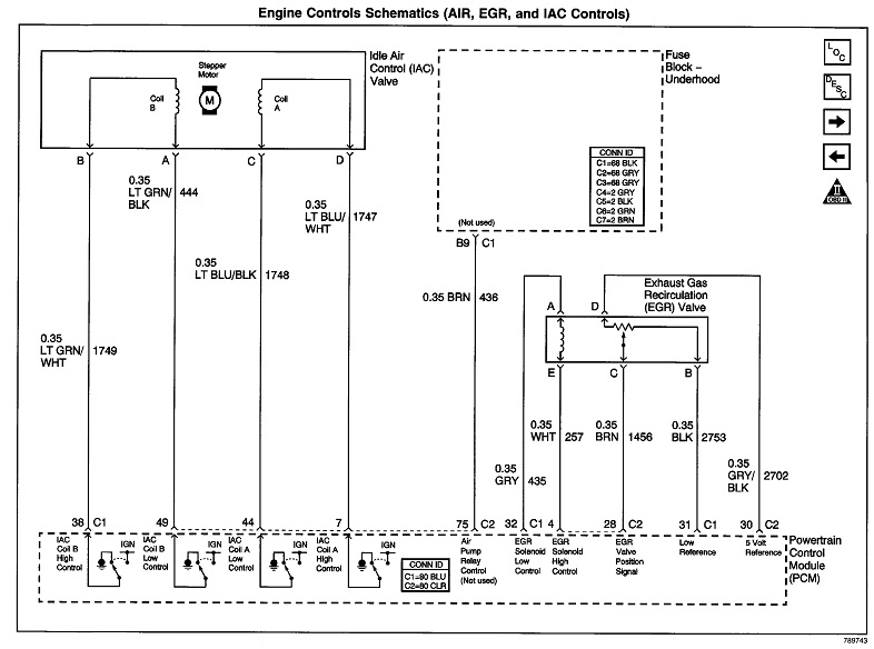
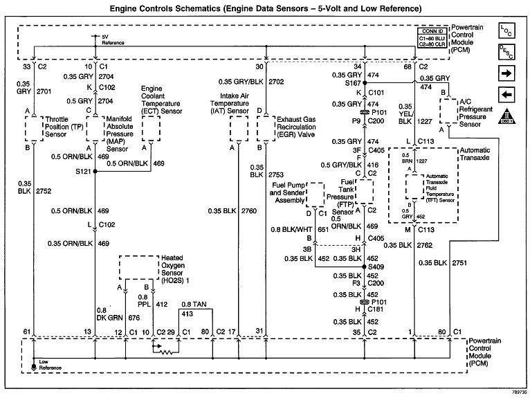
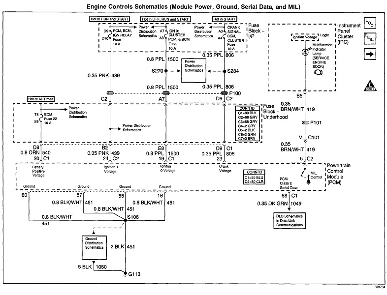
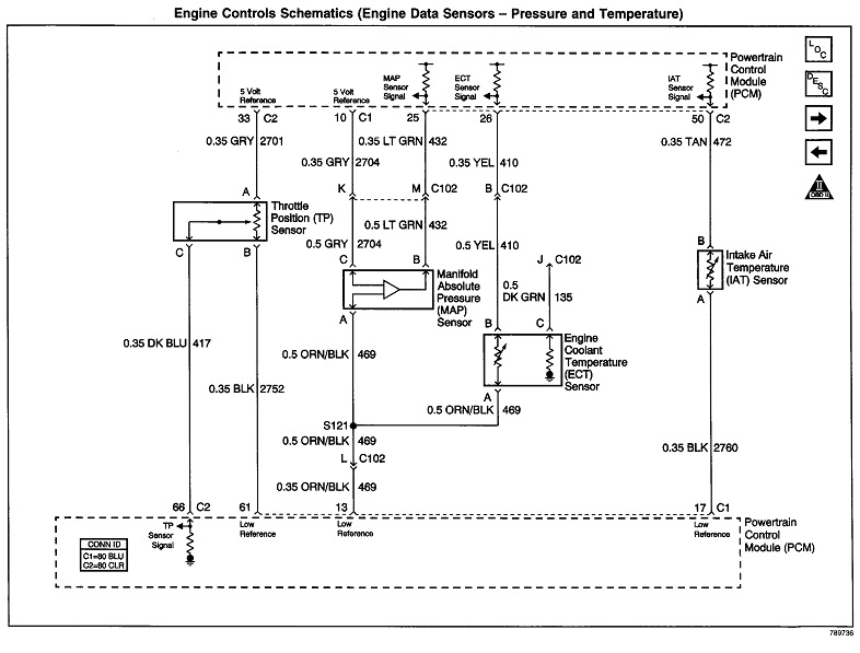
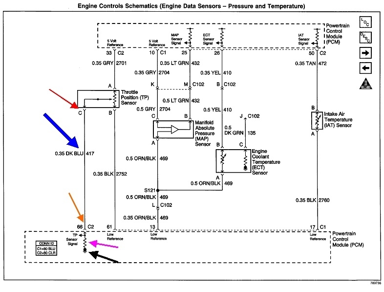
The ECT, MAP, IAT, and TPS all share a common 5.0-vot supply from the Engine Computer, however, part of the ECT's circuit is inside the computer, so there is no 5.0-volt wire at that sensor. All of these sensors also share a common ground wire, but it goes through the computer first so it can be monitored, then it goes to ground. You'll typically find 0.2 volts on that ground wire. This is the only circuit that can be connected with that added-on wire you found. Your scanner is showing 195 degrees for the ECT, so that sensor is working correctly and has to be wired correctly.

As for "key-on / engine-on or off, the scanner will tell you when it is unhappy. To do the engine speed function, the engine has to be running. I'm not aware of any test that lets you run the idle speed motor with the engine off. Most scanners require the engine to be not running to erase diagnostic fault codes, but I was just helping my friend at his body shop, and on a 2019 Chevy Equinox, the codes could only be erased with the engine running. That was a first for us, and we were surprised to find that.

My scanners will read road speed and the state of each cruise control switch any time, but it will not allow the servo's solenoids to be activated unless the engine is not running. That avoids activating the "vacuum" solenoid while you're driving. To do so could mean they find you in the next county going 120 mph!

Sensor data, switch state, (on or off), and output condition, meaning is a relay or solenoid being turned on, can all be viewed regardless if the engine is running or not. In addition, some scanners for some car models will generate a screen list of data specifically related to a crank / no-start condition. To avoid confusion, my DRB3 lists switches as "pressed" or "released" rather than "on" or "off". A brake light switch and a door switch are off when they're pressed. A horn switch is on when it's pressed.

For the engine speed test, mine doesn't allow me to select a speed lower than normal idle speed. As I recall, it starts out with the first choice being 1,000 rpm, then I can only select an up or down arrow to go to 1,200, 1,400, 1,600, 1,800, and 2,000. From there I have to use the down arrow or select, "stop" to exit the test and bring it back down to normal idle speed. Any defect, a vacuum leak, for example, that results in a high idle speed will over-ride what the computer is trying to do during the engine speed test. If the scanner is telling the computer to run the engine at 1,400 rpm, for example, it can't do that if something else is already making engine speed 1,500.

The Engine Computer looks at a lot of sensor data and operating conditions to calculate the desired idle speed and ignition timing. It is very unlikely to calculate the wrong speed. There are four driver circuits inside the computer that operate the idle speed motor. Together they cause a slowly-rotating magnetic field inside that motor that the armature follows. As the armature rotates, it is on a threaded shaft that retracts or extends the pintle valve. If any one of those driver circuits were to develop a shorted driver transistor, or some other defect, that magnetic field inside the idle speed motor would no longer rotate. Some of the coils would pulse, but at most, the armature would just twitch back and forth. Engine speed would not adjust by the computer. If you were to remove the idle speed motor and forcibly push the valve in, then install it that way, idle speed would be way too high, the computer would try to bring it down, but actual engine speed wouldn't change. A quick way to see if the computer is working is to do anything that lowers engine speed, then see if the computer can bring it back up. I saw a horrendous example of this at a Chrysler training class some years ago. With a V-8 Jeep engine, the instructor unplugged one fuel injector. Almost immediately, the idle steps went from 32 to 50, and idle speed stayed right were it was supposed to be. By the end of the demonstration, he had six of the eight injectors unplugged, and idle speed was still correct. Obviously the engine was running very poorly, but his comment was, "this shows how much control the computer has over engine speed".

If you had a problem with the computer or the idle speed motor and circuit, engine speed would drop if an injector was unplugged or you had a spark-related misfire. You can also introduce an artificial vacuum leak that causes idle speed to be too high, then watch the steps, or "counts" to see if they come down. If you see the counts at around five to ten, the computer is trying to lower engine speed, but without success. "Without success" means whatever is causing the high idle speed is beyond the computer's control. It does have control of the desired (variable) vacuum leak which is the air passage the idle speed motor sits in, but it doesn't have control of a vacuum hose you pulled off, of some other vacuum leak.

Another way to verify the idle speed system is working is to remove the idle speed motor but keep it plugged in, then watch the valve when you turn the ignition switch on and off. At some point the valve will extend fully, then retract a small amount. That could occur when you turn the ignition switch on, but I see it more when the switch is turned off. By fully extending the valve more counts than necessary, the computer is sure it is extended as far as possible, so it is confident it knows where it is. It is "in sync" now in case it moved out-of-sync a few counts during the last drive cycle. Now the computer retracts the valve a predetermined amount to provide that idle flare-up to 1,500 rpm at the next engine start-up.

Your scanner can't bypass the Engine Computer. When working with the Engine Computer, there are basically only four wires in use in the scanner's cable. Those are the ground, the 12-volt feed, and two "data buss" wires. The Engine Computer, Transmission Computer, instrument cluster, Body Computer, Anti-Lock Brake Computer, and Air Bag Computer all need to know road speed, but there are not speed sensors for each one of them. Multiple computers need to know coolant temperature because they modify how they send commands based on engine temperature, but there's only one coolant temperature sensor, not one for each computer. Instead, each computer takes a turn at sending its data out onto the data buss to every other computer. It's up to those other computers whether they want to look at the data they're receiving. For a fraction of a second, the Engine Computer will transmit engine speed, temperature, load, intake air temperature, whether or not the charcoal canister's purge valve is activated, and the AC compressor relay is turned on.

At this time, the Transmission Computer looks at that data, and modifies its shift schedules according to coolant temperature, engine speed, engine load, and throttle position. It sees but ignores things like the charcoal canister's purge valve. Eventually the Transmission Computer gets a turn at transmitting data onto the data buss. Among other things, it transmits road speed. Now the Body Computer can see that and turn on speed-sensitive door locks. The radio is also connected to the data buss. It can raise the volume above a certain speed to overcome road noise.

The scanner is just one more computer connected to the data buss. (By the way, a '99 Cadillac could have up to 47 computer modules on the data buss). That means anything the scanner displays had to come through those two wires, and anything you ask the computer to do also goes through those two wires. Nothing can be activated by you without the commands going through one of the computers. You're telling the scanner to talk to the computer, then the computer responds by doing what you asked it to do.

When you run into a data buss, you can identify them by observing the pair of wires are twisted around each other. We used to do the same thing with the older flat "twin lead" for tv antennas. Any stray magnetic field will induce a voltage into a wire it crosses. By twisting the pair of wires, those voltages are induced equally in both wires, so the difference is "0", and they cancel each other out. This becomes a bigger problem because the signal voltages on the data buss wires is so small. They start out with 6.0 volts on each one, then, when a digital pulse comes along, those voltages rise by 0.2 volts on one wire, and fall by 0.2 volts on the other one. In a harness with lots of wires, there's pulses from firing the ignition coils and injectors, along with other switched circuits. Being fairly high-current circuits, they generate large magnetic fields which induce large voltage spikes into adjacent wires. That doesn't bother lighting or most other circuits, but it can seriously affect sensor signal circuits and those on the data buss.

In later years there are multiple data busses on most cars. Some are high-speed circuits that are needed to process signals immediately. One of those is for the Engine Computer so it can modify fuel metering and ignition timing calculations quickly for best performance and lowest emissions. The Air Bag also uses a high-speed data buss so it can pop the air bag at the exact instant it needs to. A low-speed data buss is used for less critical systems such as for lights, horn, and gauges. It doesn't matter if those take a few extra milliseconds to do their thing.

I have to say this next comment carefully, but at least with Chrysler products, there is nothing you can do, short of outright sabotage, to damage an Engine Computer. If you ground the 5.0-volt sensor supply to short it to ground, the computer will turn it off to protect it. Once that short is removed, you simply turn the ignition switch off, then back on to reset the supply. If sensor signal wires are grounded or shorted to 5.0 volt or even 12 volts, the computer will detect that and set the appropriate fault codes. Those incorrect voltages don't do any damage. Anything with a coil of wire will generate a reverse voltage spike of up to 300 volts when current through it is turned off. Relays have damping diodes built in to short out those spikes, and the computer has damping diodes for the switching circuits for the injectors, ignition coils, and solenoids it operates. If you look at the wiring diagrams, you'll see a lot of switching done by the computer is done on the ground side of relays and solenoids. That makes any voltage spikes appear on the 12-volt side where they are easily damped and absorbed by the battery.

GM and Chrysler do things very much the same way, but during the '80s and '90s, Engine Computer failures on Chrysler products were extremely rare. GM, on the other hand had a real lot of failures in the early '90s, but those were not caused by external defects in the cars. If a replacement computer was needed, and that replacement also had a problem, chances are that replacement was a used one from a salvage yard. By '98, GM didn't have any more computer trouble than any other manufacturer.

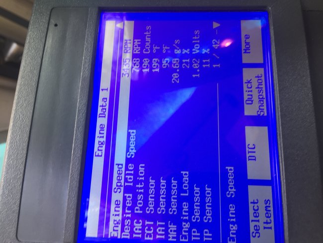
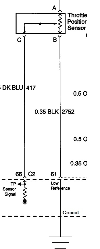
GM and Chrysler use the same idle speed motor, but while Chrysler's range goes from "0" to "256", I don't know if GM uses the same scale. If they do, your screen is showing 190 steps, which is way too high. I don't think that 8-cylinder Jeep running on only two cylinders reached that high of a step. Remember, if something such as a vacuum leak was causing your idle speed to be too high, the counts would be real low, indicating the computer was closing the idle speed motor's valve to reduce air flow. It's not doing that. Yours is showing the computer is requesting that high idle speed. That has to be in response to a sensor value or something it is seeing. Of notable interest is "engine load" of 21 percent. I don't recall seeing that on my vehicles, but it seems too high for a vehicle idling in "park". I also question the TPS voltage. I'm used to seeing around 0.6 to maybe 0.7 volts at closed throttle. Remember my story of the TPS that latched in various positions? With the engine running, the only fairly constant symptom was idle speed just high enough to get my attention, ... Perhaps 1,000 rpm. That's when I noticed the TPS was at around 2.6 volts, or incorrectly telling the computer "half throttle".

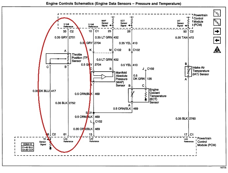
From what I've read so far, I think your observation of the TPS voltage varying at closed throttle is the thing to pursue. A comment I post quite often is, "when a part is referenced in a fault code, it is actually the cause of that code only about half of the time. The other half are caused by wiring and connector terminal problems, or mechanical problems associated with that part". The same holds true when there's no fault code being set but the signal voltages are wrong. The TPS is strictly a mechanical sensor with no touchy electronics inside. As such, it is fairly immune from sending a wrong voltage compared to electronic sensors like the MAP and MAF. Even if a tiny chip of carbon were to break off from the resistor element and get caught under the movable contact, you still wouldn't see the TPS signal voltage change when the throttle was being held steady. What is much more likely to change on its own is wiring, particularly connector terminals. What is your understanding of electrical theory? If there is some corrosion between the pair of mating connector terminals for the ground circuit, the signal voltage would go high intermittently. Likewise, if there was some corrosion on the terminals for the 5.0-volt supply, the signal voltage would drop intermittently. Remember too both the 5.0-volt supply and the ground wires feed multiple sensors, so there's going to be splices, and those are dandy places to find corrosion and bad connections.

Were I think I would start is by monitoring the TPS signal voltage with the engine off, and the throttle propped open half way. That will make any tiny glitch caused by the ground circuit to be more easily noticeable. Use a separate digital voltmeter for this. Now wiggle the harnesses and plugs. The signal voltage should hold rock solid. I could see it bouncing around a couple hundredths of a volt due to stray magnetic fields or other circuits in the car turning on or off, but if you see it change even a tenth of a volt, I'd look at what I was doing that caused that to happen. Watch the readings on the scanner at the same time. If those readings change while those on the voltmeter don't, suspect a problem in the signal wire.

Also look at all the other sensor voltages to see if something doesn't look right. You're showing 95 degrees for intake air temperature. Is it really that hot, or could that be from engine heat migrating up to the IAT while the engine isn't running?
Was this
answer
helpful?
Yes
No
Monday, October 12th, 2020 AT 8:00 PM
Tiny
FIXTHISONE
  • MEMBER
  • 34 POSTS
Once again thanks for taking the time to explain all these things in such detail.
I have ordered a probe for my DMM along with a companion book that should explain the electrical troubleshooting process. I want to use this, just like a pilot uses a check list, to make sure that I don't leave anything out.
The varying voltage, in my head, would be caused by a damaged wire that only has a strand left.
Even though the current isn't much the electricity could cause a resistance variance and also the " intermittent" aspect of the problem.
Vibration+ resistance due to corrosion, as I drive the car would cause these values to jump erratically.
Once I get the probe and the book, I will do the testing and let you know what happens.
Thank you
Was this
answer
helpful?
Yes
No
Tuesday, October 13th, 2020 AT 7:11 AM

Please login or register to post a reply.

Sponsored links