Hi and thanks for using 2CarPros.com.
To the best of my knowledge, yes. Actually, I believe all Nissan engines are interference engines. The best way to check is to correctly time the engine and perform a compression test.
https://www.2carpros.com/articles/how-to-test-engine-compression
If you have a bent valve, there will be little to no compression in the affected cylinder.
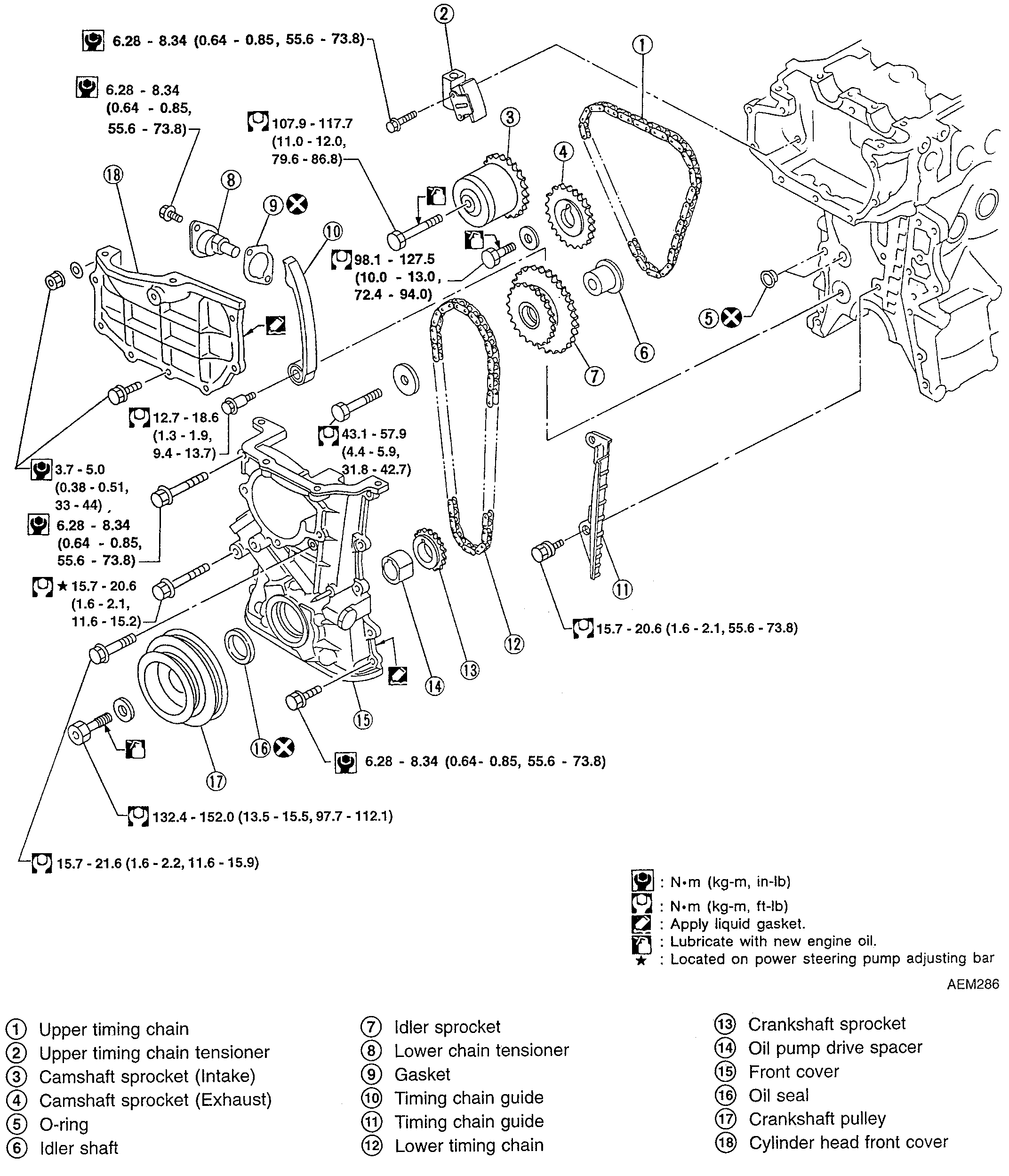
I do not know if you need it, but I figured I would give you the removal and replacement directions for the timing chain. First will be removal directions followed by replacement. All attached pictures correlate with these directions.
________________________________
Caution:
- After removing the timing chain, do not turn the crankshaft and camshaft separately or the valves will strike the piston heads.
- When installing chain tensioners or other sliding parts, lubricate contacting surfaces with new engine oil.
- Apply new engine oil to bolt threads and seat surfaces when installing the camshaft sprockets and the crankshaft pulley.
- Do not spill engine coolant on the drive belts.
- Please use the correct tightening torque.
1. Set # 1 piston at TDC on its compression stroke.
2. Remove the spark plug wires.
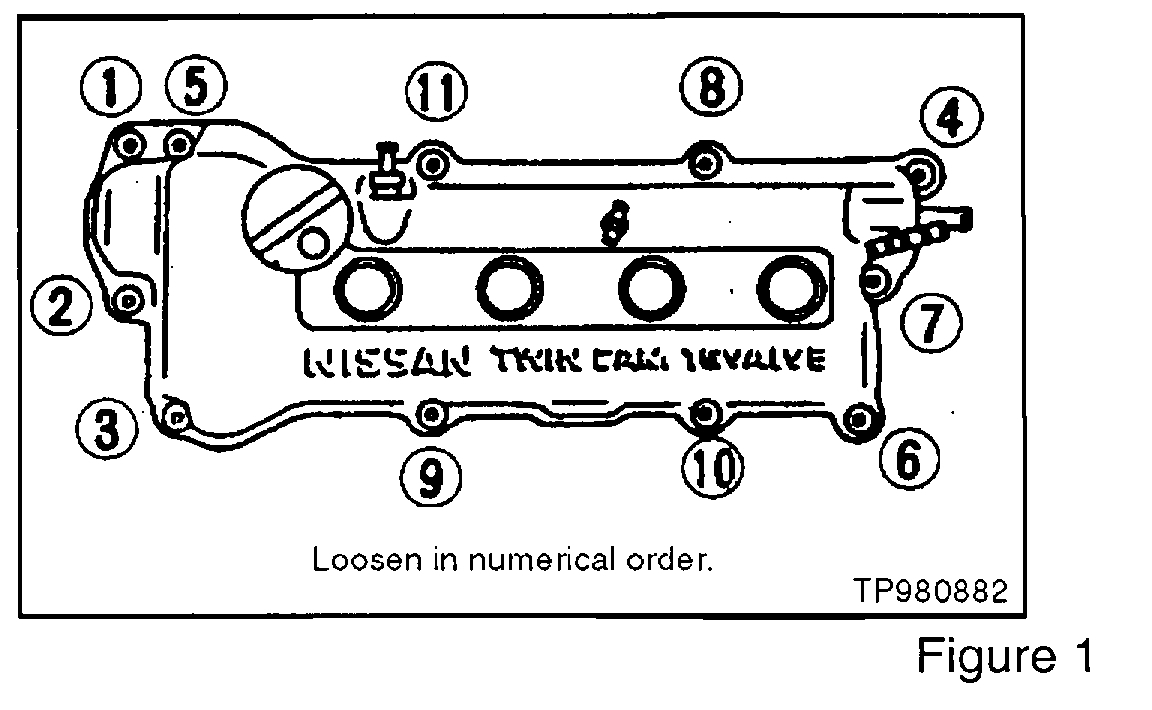
3. Remove the rocker cover (see figure 1). 4.Remove the coolant reservoir tank with bracket and reposition it for clearance.
5. Support the engine with a suitable jack.
6. Remove cylinder head front mounting bracket.
7. Remove engine front mounting, then the engine front mounting bracket.
8. Remove cylinder head front cover.
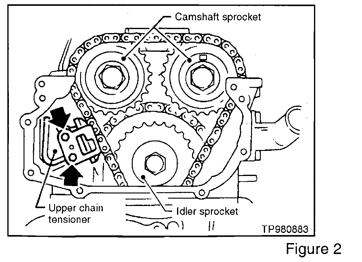
9. Remove the upper chain tensioner (see figure 2).
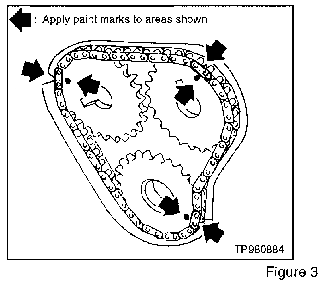
10. Wipe off the links of the upper timing chain next to the timing marks on the sprockets. Put paint marks on the timing chain, matching them with the timing marks on the cam sprockets and idler sprocket (see image 3)
11. Remove the four (4) front cover to cylinder head bolts.
12. Remove side and lower engine compartment splash covers.
13. Remove the accessory drive belts.
14. Remove the crankshaft pulley.
15. Drain coolant by removing the cylinder block drain plug and opening the radiator drain cock.
16. Drain engine oil.
17. Remove intake manifold support of engine front side.
18. Remove power steering pump, pump bracket and tension rod. Position pump aside for clearance.
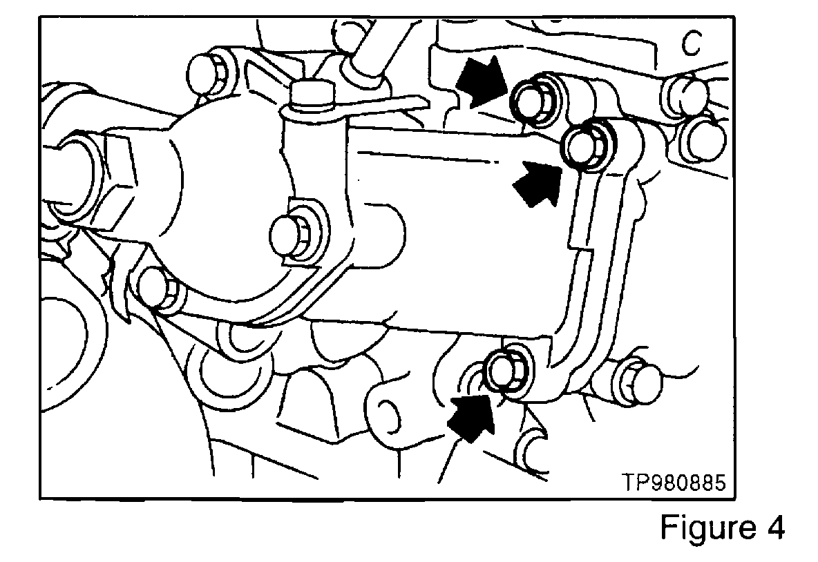
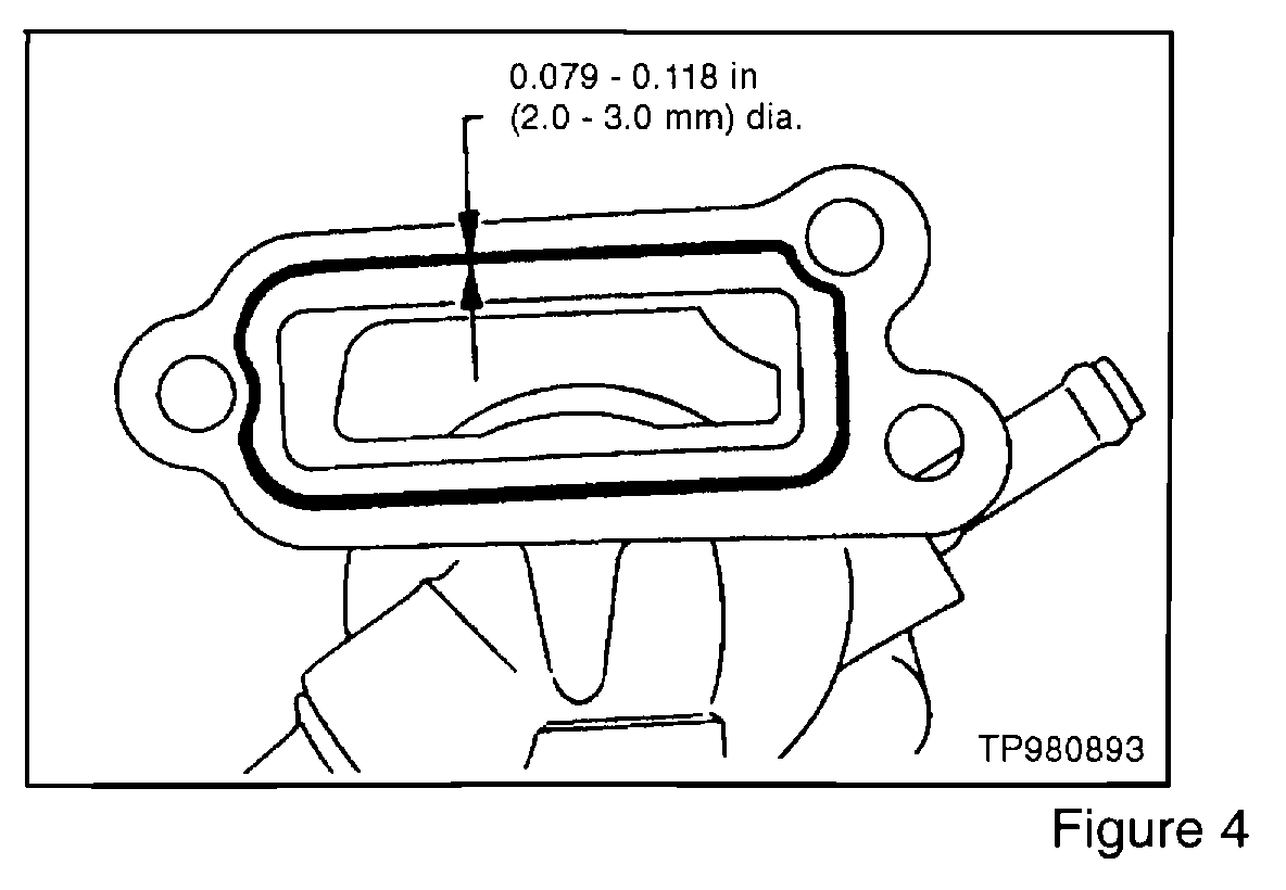
19. Remove the thermostat housing (See figure 4).
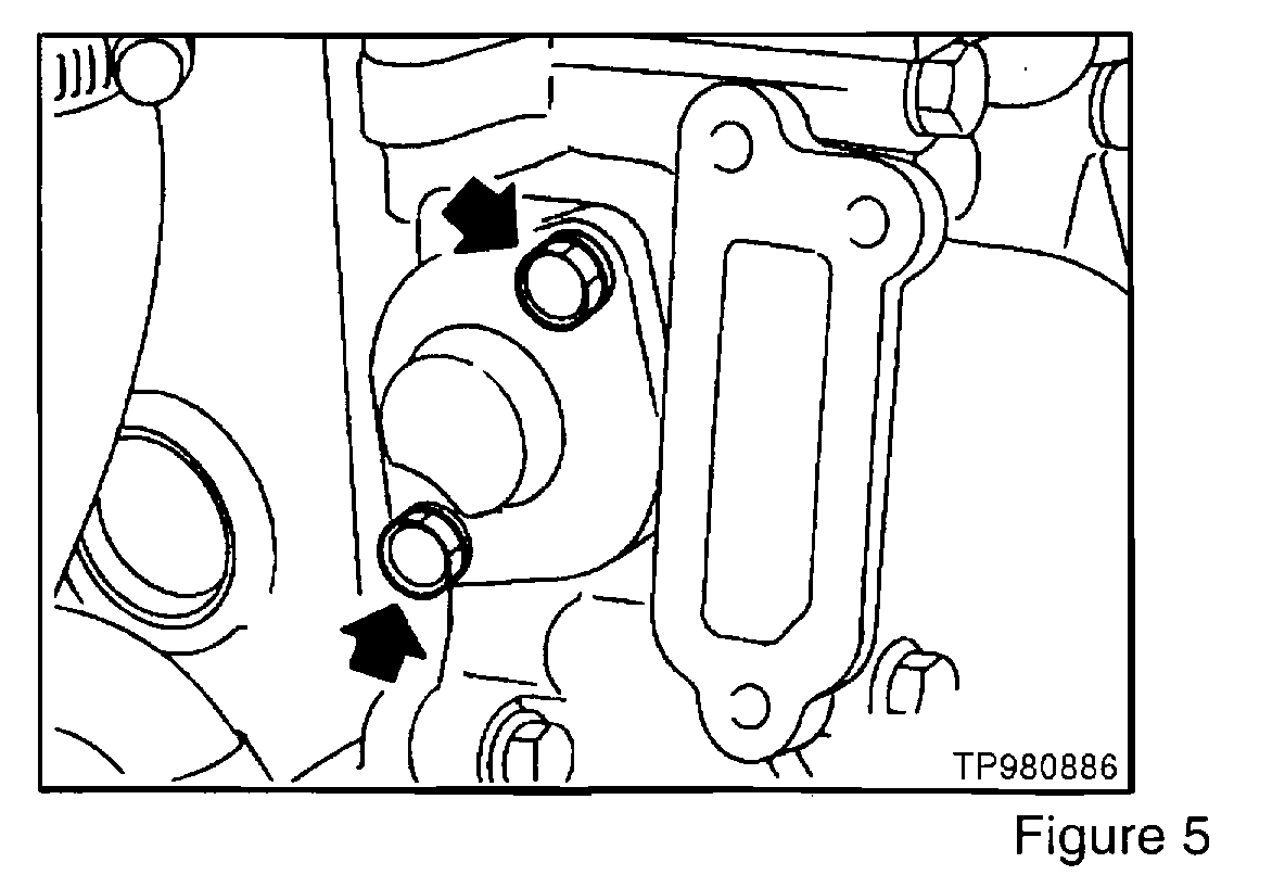
20. Remove the lower chain tensioner (see figure 5).
21. Remove the front exhaust tube.
22. Remove the front and rear engine gussets (if equipped) on either side of the oil pan.
NOTE:
On A/T models, remove the rear plate cover.
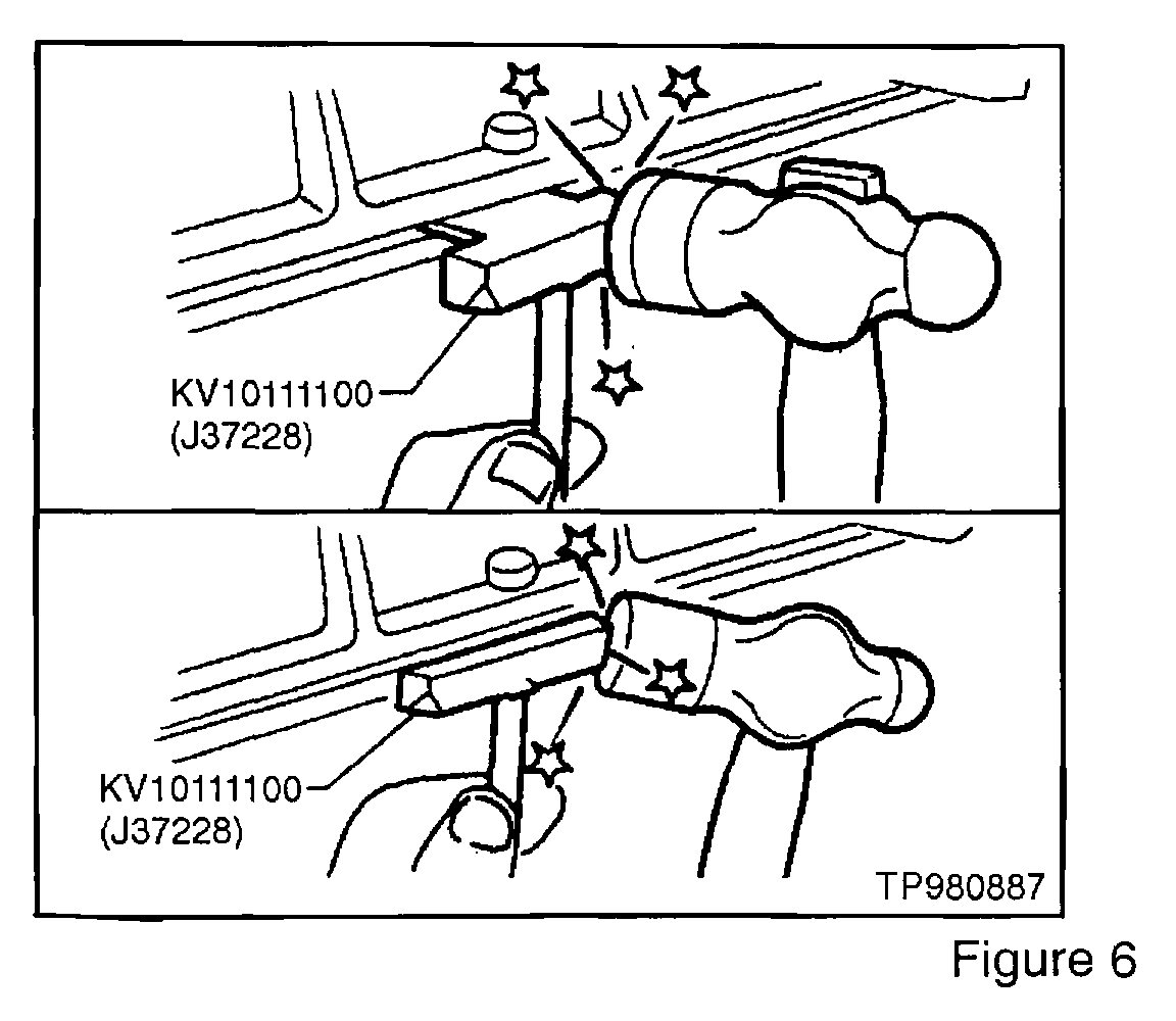
23. Remove the oil pan (see figure 6).
a. Insert the tool between the cylinder block and oil pan.
CAUTION:
Be careful not to damage the aluminum mating face. Do not insert a screwdriver, or the oil pan flange will become damaged.
b. Slide the tool by tapping it on the side of the tool with a hammer.
24. Remove the A/C compressor and position it aside for clearance.
25. Remove the A/C and alternator bracket with the alternator.
26. Remove the oil pump drive spacer.
CAUTION: Be careful not to scratch the drive spacer when removing it.
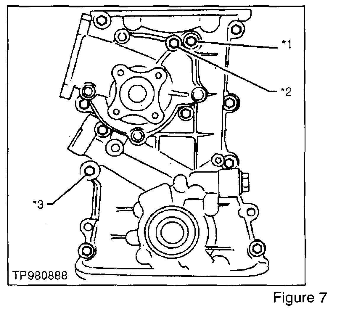
27. Remove the front cover bolts and front cover.
CAUTION:
One bolt is located on the water pump (see figure 7).
*1: Located on engine front mounting bracket.
*2: Located on the water pump.
*3: Located on the power steering oil pump adjusting bar.
CAUTION: Be careful not to tear or damage the cylinder head gasket.
28. Remove the cylinder block to front cover alignment dowels.
CAUTION: Do not hit the dowels or the cylinder block will crack.
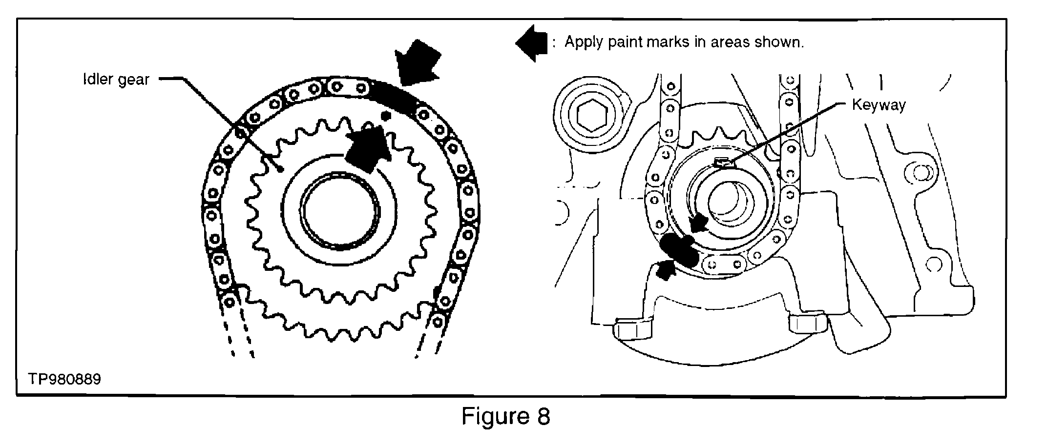
29. Wipe off the links of the lower timing chain next to the timing marks on the sprockets. Put paint marks on the timing chain, matching them with the timing marks on the idler sprocket and crankshaft sprocket (see image 8).
______________________________
Replacement:
1. Install the crankshaft sprocket, making sure the mating marks face the front of the engine.
2. Install the idler sprocket and lower timing chain using the mating marks and the paint marks made during the removal process.
CAUTION: Be careful not to tear or damage the cylinder head gasket.
3. Install the lower chain guides.
4. Front cover installation:
a. Using a scraper or other suitable tool remove all traces of liquid gasket from the cylinder block and front cover mating surfaces.
b. Install new crankshaft seal in front cover.
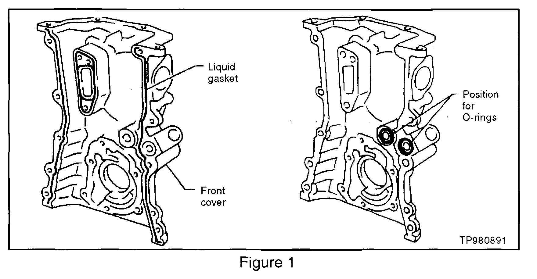
c. Install new oil passage O-rings and apply a continuous bead of RTV sealant to the front cover (see figure 1).
NOTE: Use Genuine Nissan RTV silicone sealant P/N 999MP-A7007, Three Bond P/N TB1207D or equivalent.
d. Install the front cover to the engine.
CAUTION: Be careful not to tear or damage the cylinder head gasket or oil seal.
5. Align oil pump drive spacer with the oil pump, and install.
6. Install the oil strainer.
7. Install oil pan.
8. Install upper timing chain and sprockets, using the painted reference marks made during removal.
9. Install upper chain tensioner.
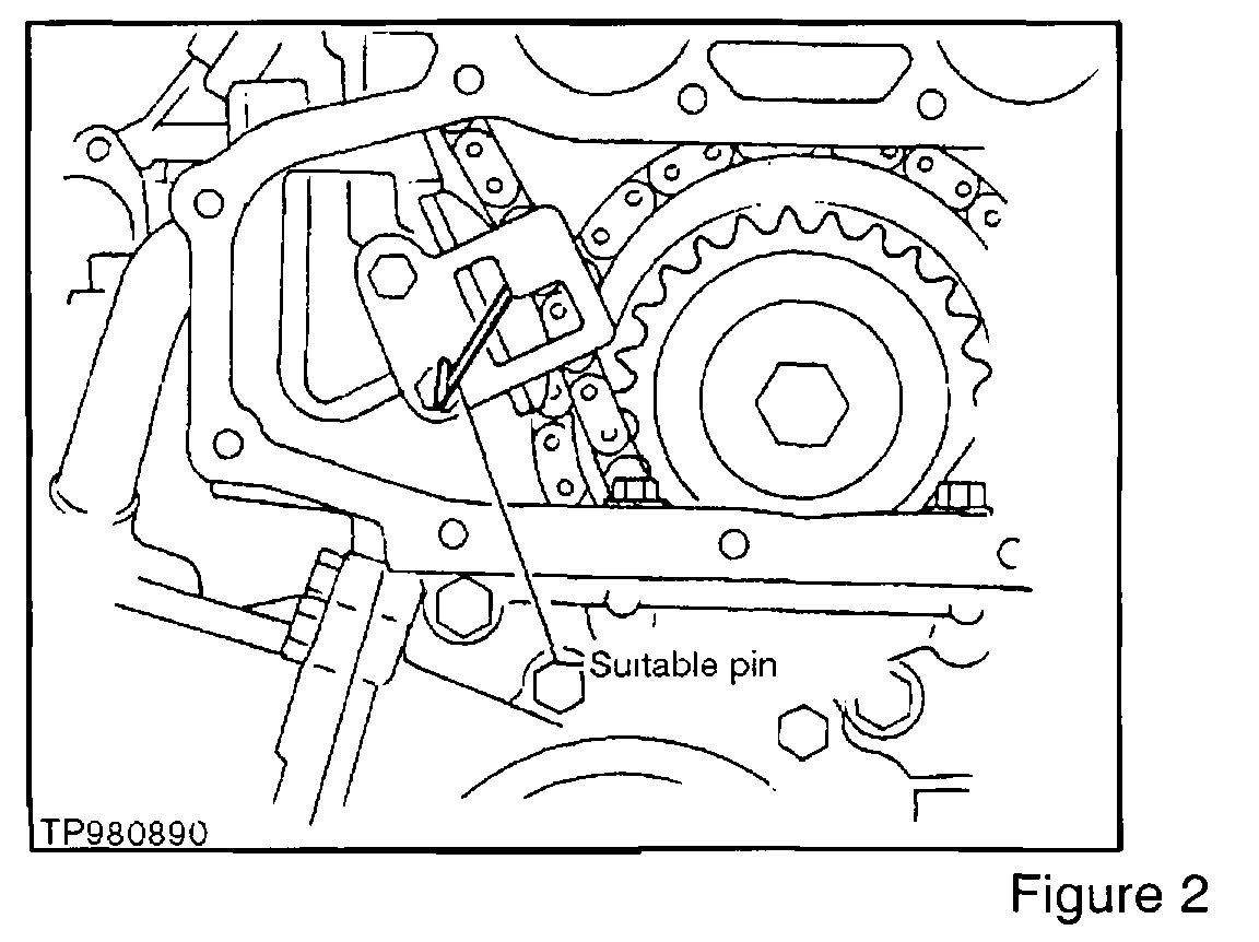
a. Before installing the chain tensioner, insert a suitable pin into the pin hole of the chain tensioner (see figure 2) to hold the tensioner in.
b. Once the tensioner is installed, remove the pin.
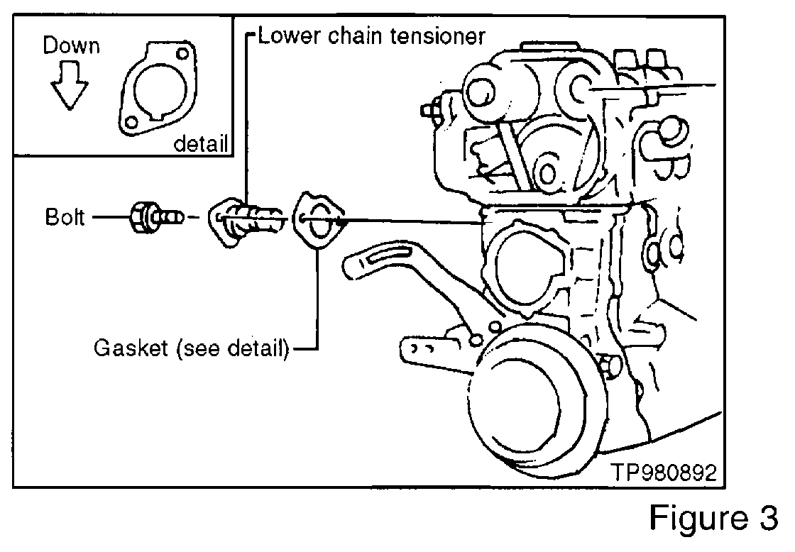
10. Install the lower chain tensioner (See figure 3).
NOTE:
Make sure the gasket is facing the proper direction before installing the tensioner.
CAUTION: Now rotate the crankshaft by hand. Check that no binding or interference problems occur when the engine is rotated.
11. Install the thermostat housing.
a. Use a scraper to remove all traces of liquid gasket from the mating surfaces of the engine front cover and the thermostat housing.
b. Apply a continuous bead of RTV sealant to the housing as shown in image 4.
NOTE: Use Genuine Nissan RTV silicone sealant P/N 999MP-A7007, Three Bond P/N TB1207D or equivalent.
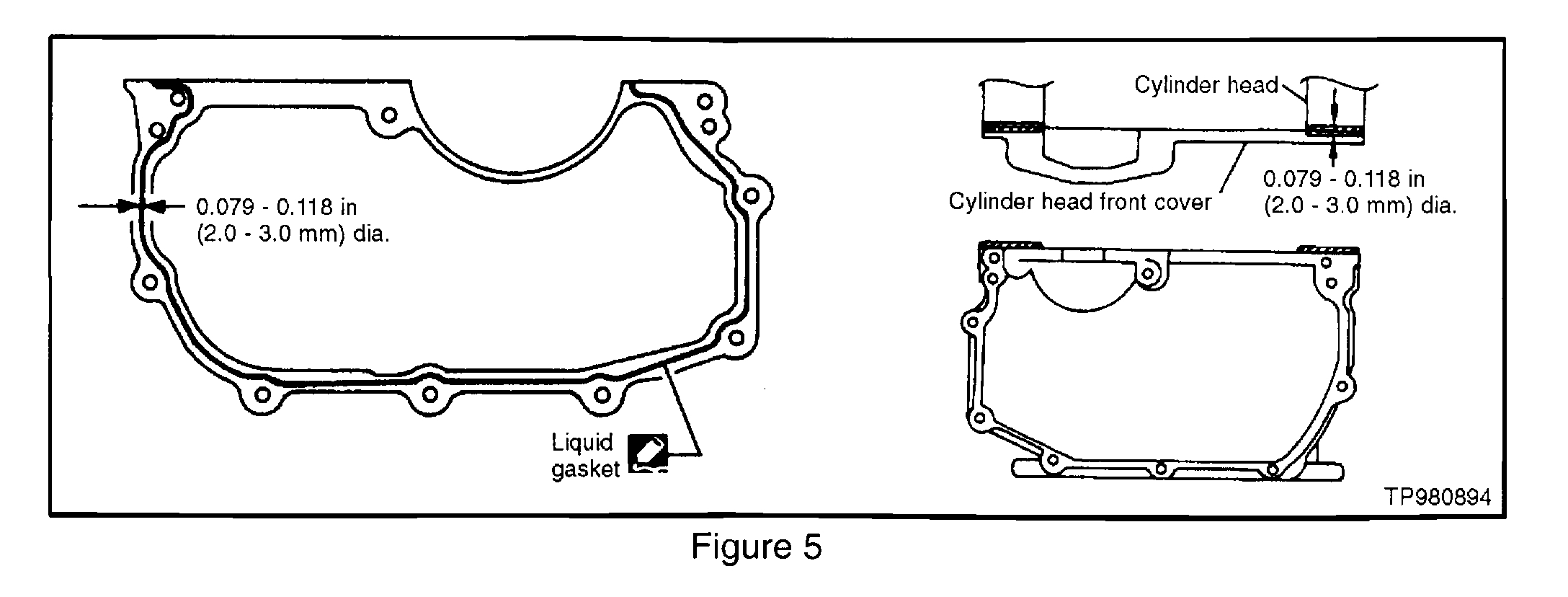
12. Install camshaft sprocket cover:
a. Use a scraper to remove all traces of liquid gasket from the mating surfaces of the cylinder head and camshaft sprocket cover.
b. Apply a continuous bead of RTV sealant to the cover as shown in image 5.
NOTE: Use Genuine Nissan RTV silicone sealant P/N 999MP-A7007, Three Bond P/N TB1207D or equivalent.
c. Install camshaft sprocket cover.
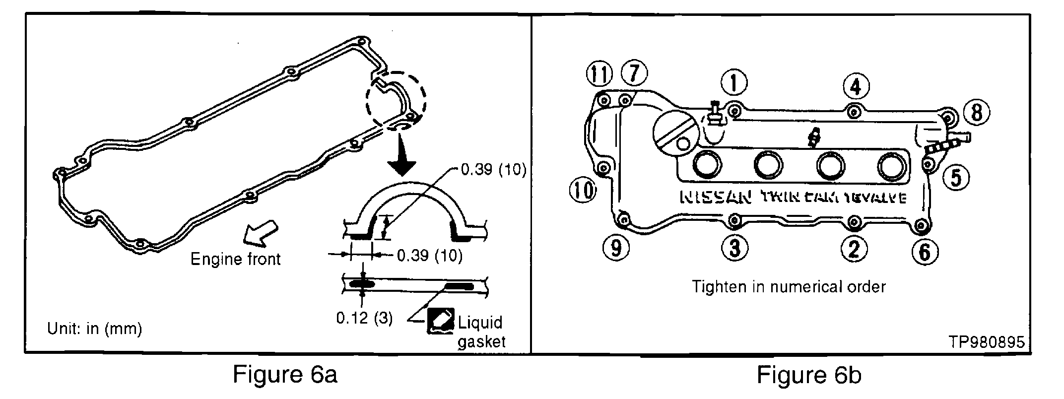
13. Apply RTV sealant to rocker cover gasket (see figure 6a) and install rocker cover, tightening the bolts as shown in figure 6b. 14.Install the following parts:
a. Crankshaft pulley.
b. A/C compressor and alternator bracket with alternator.
c. A/C compressor.
d. Power steering oil pump and tension rod.
15. Install front and rear engine gussets (if equipped), and rear cover plate (A/T models).
16. Install front exhaust tube.
17. Install upper right engine bracket and mount.
18. Install coolant reservoir tank.
19. Install alternator, power steering and A/C compressor drive belts.
20. Install engine compartment splash guards.
21. Install vacuum hoses, electrical harnesses and connectors.
22. Install spark plug wires.
23. Refill with coolant.
24. Refill with engine oil.
_____________________________________________
I realize this isn't great news. However, if I can help, let me know.
Take care,
Joe
Images (Click to enlarge)
Oct 30, 2018 at 7:15 PM