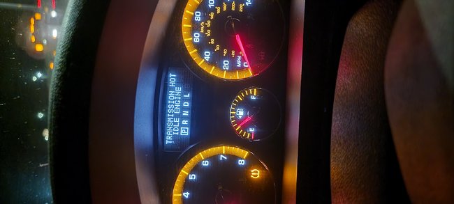
How do you know it is overheating?
The one reason it may be overheating is a clogged cooler. If it was not flushed out, there could be no cooling of the fluid and it will heat up the fluid.
Below is the procedure for flushing the cooler.
Roy
Transmission Fluid Cooler Flushing and Flow Test (Outlook)
GM studies indicate that plugged or restricted transaxle oil coolers and line cause insufficient transaxle lubrication and elevated operating temperatures which can lead to premature transaxle wear-out. Many repeat repair cases could have been prevented by following published procedures for transaxle oil cooler flushing and flow checking. This procedure includes flow checking and flushing the auxiliary transaxle oil cooler, if equipped.
Note: Use the SA 9165T - line flusher or equivalent to flush the transaxle oil cooler and the oil cooler line whenever the transaxle is removed for the following repairs:
* Torque converter
* Oil pump
* Transaxle overhaul complete
* Transaxle assembly replacement
Use the appropriate transaxle fluid when performing a transaxle repair. Only GM Goodwrench DEXRON(R)VI automatic transaxle fluid should be used when doing a repair on a six (6) speed GM transaxle.
Time allowance for performing the cooler flow checking and flushing procedure has been included in the appropriate labor time guide operations since the 1987 model year. The service procedure steps for oil cooler flushing are as follows:
Cooler Flow Check and Flushing Steps
1. Tools Required
2. Preparation
3. Back Flush
4. Forward Flush
5. Flow Check
6. Clean-up
Special Tools
* DT-48312 - Transmission Cooler Flushing Adapter
* J 35944-22 - Cooler Flushing Fluid
* SA 9165T - Oil Cooler Line Flusher
* Measuring Cup
* Funnel
* Water supply - hot water recommended
* Water hose, at least 16 mm (5/8 in) ID
* Shop air supply with water/oil filters, regulator and pressure gage
* Air chuck with clip, if available
* Oil drain container
* Pail with lid - 19 L (5 gallon)
* Eye protection
* Rubber gloves
For equivalent regional tools, refer to Special Tools (See: Automatic Transmission/Transaxle > Electrical / Mechanical Repair).
Preparation
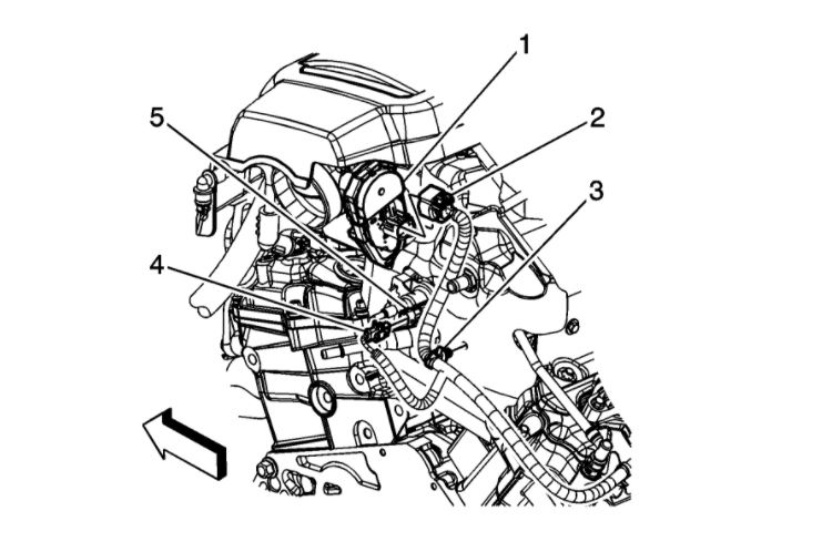
1. During the installation of the repaired or replacement transaxle, do not connect the oil cooler lines.
ImageOpen In New TabZoom/Print
Caution: Do not use solutions that contain alcohol or glycol. Use of solutions that contain alcohol or glycol may damage the oil cooler line flusher, oil cooler components and/or transmission components.
Note: The J 35944-22 - flushing fluid is environmentally safe, yet powerful enough to cut through transaxle fluid to dislodge any contaminants from the cooler. The safety precautions on the label, regarding potential skin and eye irritations associated with prolonged exposure, are typical precautions that apply to many similar cleaning solutions. It should be noted that according to GM, use of other non-approved fluids for cooler flushing can have an adverse reaction to the seals inside the transaxle.
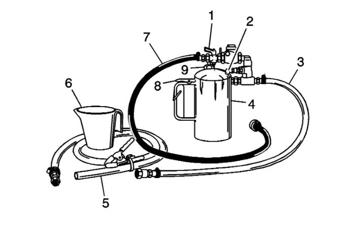
2. Remove the fill cap (9) on the SA 9165T - line flusher and fill the flusher tank (4) with 0.6 L (20-21 oz) of J 35944-22 - flushing fluid, using the measuring cup (6). Do not overfill.
3. Install the fill cap (9) on the SA 9165T - line flusher and pressurize the flusher tank (4) to 550-700 kPa (80-100 psi), using the shop air supply at the tank air valve (2).
4. With the water supply valve (1) on the SA 9165T - line flusher in the OFF position, connect the water supply hose from the SA 9165T - line flusher to the water supply at the faucet.
5. Turn ON the water supply at the faucet.
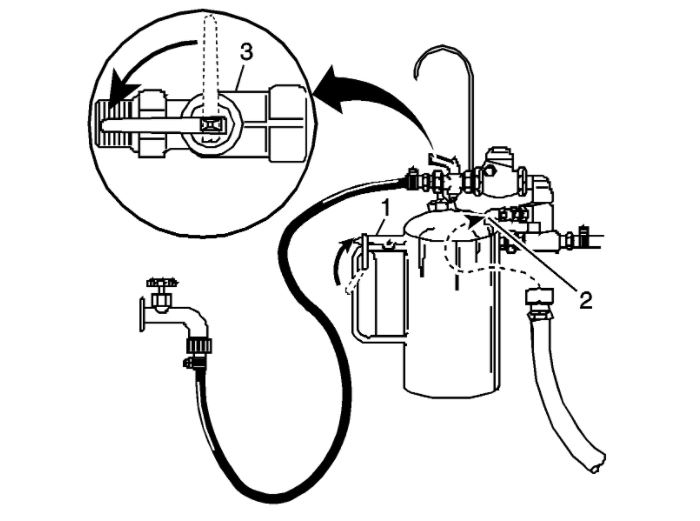
Back Flush
imageOpen In New TabZoom/Print
Note: Inspect the transaxle oil cooler lines for kinks or damage. Repair as necessary.
1. Connect the SA 9165T - line flusher to the oil cooler feed line. Use the DT-48312 - flushing adapter.
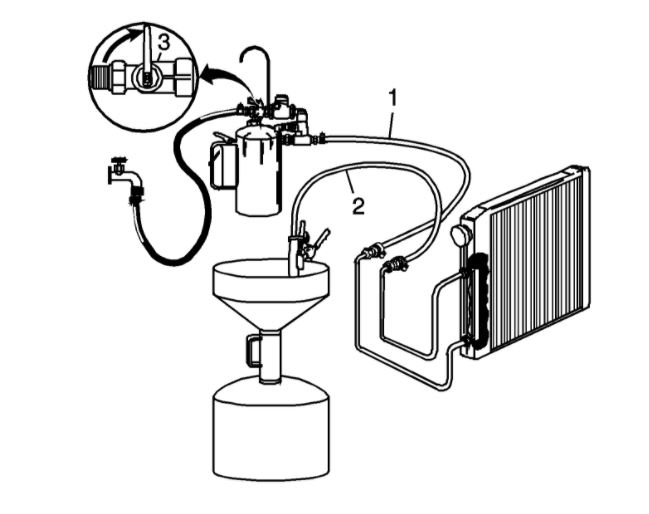
2. Clip the discharge hose (2) onto the oil drain container.
3. Attach the SA 9165T - line flusher to the undercarriage of the vehicle with the hook provided and connect the flushing system feed supply hose (1) from the SA 9165T - line flusher to the oil cooler return line. Use the DT-48312 - flushing adapter.
4. Turn the SA 9165T - line flusher water supply valve (3) to the ON position and allow water to flow through the oil cooler and lines for 10 seconds to remove any remaining transaxle fluid. If water does not flow through the oil cooler and lines, the cause of the blockage must be diagnosed and the plugged component must be repaired or replaced. Continue with the cooler flushing and flow check procedure once the blockage is corrected.
5. Turn the SA 9165T - line flusher water supply valve (3) to the OFF position and clip the discharge hose onto a 19 liter (5 gallon) pail with a lid, to avoid splashback.
ImageOpen In New TabZoom/Print
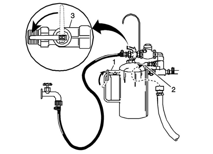
Note: Flushing for approximately 2 minutes in each cooler line direction will result in a total of about 8-10 gallons of waste fluid. This mixture of water and flushing fluid is to be captured in a bucket or similar container.
6. Turn the SA 9165T - line flusher water supply valve (3) to the ON position and depress the trigger (1) to mix cooler flushing solution into the water flow. Use the clip provided on the handle to hold the trigger (1) down. The discharge will foam vigorously when the solution is introduced into the water stream.
7. Flush the oil cooler and lines with water and solution for 2 minutes. During this flush, attach the shop air supply 550-700 kPa (80-100 psi) to the flushing system feed air valve (2) located on the SA 9165T - line flusher, for 3-5 seconds at the end of every 15-20 second interval to create a surging action.
8. Release the trigger (1) and turn the SA 9165T - line flusher water supply valve (3) to the OFF position.
Forward Flush
imageOpen In New TabZoom/Print
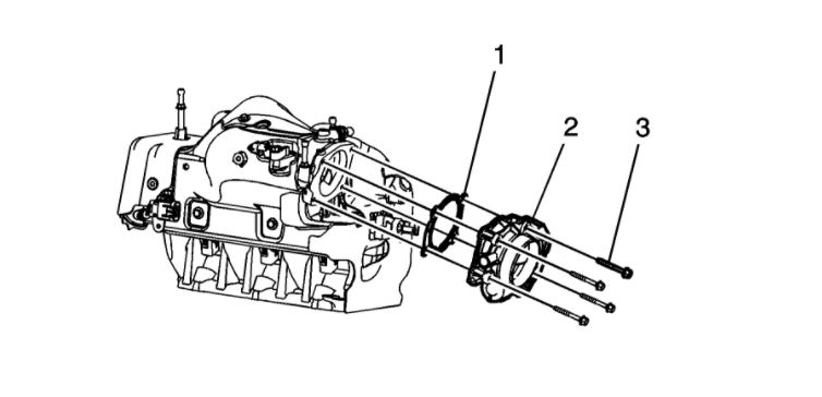
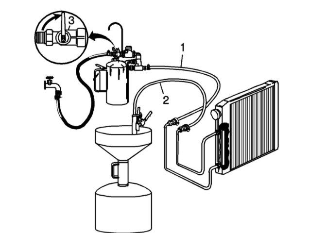
1. Disconnect both hoses (1 and 2) from the oil cooler lines and connect them to the opposite oil cooler line. This will allow the oil cooler and lines to be flushed in the normal flow direction.
2. Repeat Step 6 and 7 of the Back Flush.
ImageOpen In New TabZoom/Print
3. Release the trigger (1) of the SA 9165T - line flusher and allow water only to rinse the oil cooler and lines for 1 minute.
4. Turn the SA 9165T - line flusher water supply valve (3) to the OFF position and turn OFF the water supply at the faucet.
5. Attach the shop air supply to the flushing system feed air valve (2) on the SA 9165T - line flusher and blow out the water from the oil cooler and lines. Continue, until no water comes out of the discharge hose.
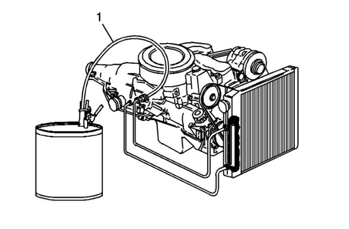
Flow Test
imageOpen In New TabZoom/Print
Note: The Flow Test must be performed after the flush to ensure that all flushing solution and water is removed from the oil cooling system. Corrosion of the oil cooler will occur if water and flushing solution remain in the oil cooling system.
1. Disconnect the hose from the oil cooler line. Connect the oil cooler feed line to the transaxle for normal flow.
2. Clip the discharge hose (1) to an empty oil container.
3. Confirm the transaxle is filled with automatic transaxle fluid. Refer to Fluid Capacity Specifications (See: Automatic Transmission/Transaxle > Capacities) for the correct automatic transaxle fluid capacity.
4. Start the engine with the transaxle in PARK range and run for 30 seconds after fluid begins to flow from the discharge hose (1). A minimum of 1.9 L (2 quarts) must be discharged during this 30 second run time.
5. If the fluid flow meets or exceeds 1.9 L (2 quarts) in 30 seconds, connect the oil cooler return line to the transaxle.
6. If fluid flow is less than 1.9 L (2 qt) in 30 seconds, perform the following diagnosis:
1. Disconnect the SA 9165T - line flusher discharge hose (1) from the oil cooler return line.
2. Disconnect the oil cooler feed line at the radiator.
3. Connect the SA 9165T - line flusher discharge hose (1) to the oil cooler feed line, radiator end.
4. Clip the discharge hose (1) onto the oil drain container.
5. Start the engine with the transaxle in PARK range and run for 30 seconds after fluid begins to flow from the discharge hose (1). A minimum of 1.9 L (2 qt) must be discharged during this 30 second run time.
7. If the amount of transaxle fluid flow remains less than 1.9 L (2 qt) in 30 seconds, inspect the oil cooler feed line for restrictions or damage. If no condition is found with the feed pipe, inspect the transaxle.
Clean-up
1. Disconnect the water supply hose from the SA 9165T - line flusher and bleed any remaining air pressure from the flusher tank.
2. Remove the fill cap from the SA 9165T - line flusher and return any unused flushing solution to its container. Rinse the SA 9165T - line flusher with water. Do not store the SA 9165T - line flusher with flushing solution in it.
3. After every third use, clean the SA 9165T - line flusher as described in the instructions included with the tool.
4. Dispose of any waste water/solution and transaxle fluid in accordance with local regulations.
Images (Click to make bigger)
Wednesday, March 24th, 2021 AT 7:07 PM