High beams issue!

Tiny
DAVE H
  • MECHANIC
  • 13,383 POSTS
The green/red wire at the instrument cluster (c3)


https://www.2carpros.com/forum/automotive_pictures/266999_AAA2_531.png

Was this
answer
helpful?
Yes
No
Sunday, April 19th, 2009 AT 11:26 AM
Tiny
MBENCO
  • MEMBER
  • 184 POSTS
I'm still not clear. Do you want me to take the dash back apart and disconect one of the connecter plugs on the back of the instrument cluster. Where is c3 located?
Was this
answer
helpful?
Yes
No
Sunday, April 19th, 2009 AT 11:43 AM
Tiny
DAVE H
  • MECHANIC
  • 13,383 POSTS
I didn't know you had put it all back together ... yes (c3) is on the back of the instrument cluster .. i would never rebuild until I have located the cause of the fault !! ...you may have to strip it all down again later ? ...forget c3 for now ... if you are getting 12 volts @ red/green #5 @ ECM and you have a good ground for your tester it should be lighting up just like the #1 is ... and when you set off the flash code sequence it should flash the codes for you !!


https://www.2carpros.com/forum/automotive_pictures/266999_AAA2_532.png

Was this
answer
helpful?
Yes
No
Sunday, April 19th, 2009 AT 11:54 AM
Tiny
MBENCO
  • MEMBER
  • 184 POSTS
The light doesn't come on when I connect it to pin #5 BUT I put a meter on the light while it's hooked up, and it showed less than 1 volt and when I put the light on #1 pin and put the meter on the light while it's hooked up, it showed 12 volts so I think when I'm hooking up the light to #5 it's causing the voltage to drop and I guess that's why the bulb won't light up. Does that sound reasonable? What do you think? The question is why is the voltage dropping off?
Was this
answer
helpful?
Yes
No
Sunday, April 19th, 2009 AT 12:04 PM
Tiny
DAVE H
  • MECHANIC
  • 13,383 POSTS
The ECM grounds the CEL so thats the reason for the voltage irregularity .. I was trying to figure out why you had 12 volts at green/red wire !! ... the CEL gets 12 volts from the gauge fuse which is HOT in start position .. the ECM grounds out the CEL ... so put a constant hot feed to your tester and ground it on the green/red wire it should stay lit @ ignition on and start flashing once you set of the flash code sequence !! BUT if it is showing voltage then the wire is good and the bulb must be BAD ...??


https://www.2carpros.com/forum/automotive_pictures/266999_AAA2_533.png

Was this
answer
helpful?
Yes
No
Sunday, April 19th, 2009 AT 12:26 PM
Tiny
MBENCO
  • MEMBER
  • 184 POSTS
OK: I hooked up a 12 volt jumper from the white/red wire and when I did the check engine light came on but it didn't show any codes
Was this
answer
helpful?
Yes
No
Sunday, April 19th, 2009 AT 1:05 PM
Tiny
DAVE H
  • MECHANIC
  • 13,383 POSTS
What white/red wire and what did you jump it too ???

Put the live from your tester to the #1 hot feed and the ground from tester to the #5 ... when you start off the flash sequence it should flash the codes on your tester !!!

I have to go out .. will be back a little later !!


https://www.2carpros.com/forum/automotive_pictures/266999_AAA2_534.png

Was this
answer
helpful?
Yes
No
Sunday, April 19th, 2009 AT 1:46 PM
Tiny
MBENCO
  • MEMBER
  • 184 POSTS
Sorry I got my colors mixed up. I jumped the #1 pin(white/blue wire) to the #5 pin(green/red) and the check engine light came on but no codes will come up. The self diagnostic system isn't working.
Was this
answer
helpful?
Yes
No
Sunday, April 19th, 2009 AT 2:09 PM
Tiny
DAVE H
  • MECHANIC
  • 13,383 POSTS
Theoretically speaking you should have blown at least the CEL bulb .. because you have just put 2 hot feeds to it ??? one from the gauges fuse and one from the red/green wire you jumped from the hot feed to the ECM.. I don't understand why it came on ?? ... this will not flash the codes for you, as you are just supplying another constant hot feed !!! the only way to flash the codes is the way I described in my last post ... I did not ask you to jump anything and I hope you have not blown the ECM now by putting another HOT feed to the gound out #5 pin ???


https://www.2carpros.com/forum/automotive_pictures/266999_AAA2_535.png

Was this
answer
helpful?
Yes
No
Sunday, April 19th, 2009 AT 7:56 PM
Tiny
MBENCO
  • MEMBER
  • 184 POSTS
I guess I'm not understanding what you want. Could you draw me a diagram showing me? Thanks I appreciate it.
Was this
answer
helpful?
Yes
No
Sunday, April 19th, 2009 AT 8:47 PM
Tiny
DAVE H
  • MECHANIC
  • 13,383 POSTS
NO jumper's ... a bulb or tester setup like this diagram... when you start off the flash code sequence .. to get the CEL to flash ... your bulb or tester will flash instead !! NOTE .. setup the bulb/tester and turn on the ignition and the bulb/tester should light up and be on constantly if there are codes stored ... just like the CEL would ...If nothing happens, the damage may already be done and you will need to swap out the ECM again ... you could have already blown it with the jumper wire ... it's late ... so I expect to hear from you tommorrow


https://www.2carpros.com/forum/automotive_pictures/266999_cam_13.jpg


let me know


https://www.2carpros.com/forum/automotive_pictures/266999_AAA2_536.png

Was this
answer
helpful?
Yes
No
Sunday, April 19th, 2009 AT 9:37 PM
Tiny
MBENCO
  • MEMBER
  • 184 POSTS
Mornin Dave: The jumper I used was the tester light. So no damage was done to the computer. I have 4 test lights and I used the heavy duty light to do the tests and I found out this morning that it wasn't giving me good readings so I changed to a different test light and with this light when I went from #5 pin to ground the CEL came on but I can't get the diagnostics to start.
Was this
answer
helpful?
Yes
No
Monday, April 20th, 2009 AT 8:04 AM
Tiny
MBENCO
  • MEMBER
  • 184 POSTS
Hey guys: I know that all the sensors are for the purpose of helping the car run better thru the computer but will any of them keep a car from getting spark to the distributer? I replaced the dist. Cap, roter, and coil, What else is there? Can you draw me a simple diagram of how the current flows from the battery to the spark plugs in this 95 camry? And if you can't that's OK.
Was this
answer
helpful?
Yes
No
Monday, April 20th, 2009 AT 2:56 PM
Tiny
MBENCO
  • MEMBER
  • 184 POSTS
Hey Dave: Just thought I'd check to see if you were still alive Ha, Ha.
Was this
answer
helpful?
Yes
No
Thursday, April 23rd, 2009 AT 6:34 PM
Tiny
DAVE H
  • MECHANIC
  • 13,383 POSTS
Hey Mike.

I'm still around ...LOL .. just very busy at work so not been around the forum much ...

ECM uses pick-up coil input signals to switch primary ignition circuit on and off. Primary circuit is turned off when ECM delivers a signal to ignitor on the IGT wire, causing ignition coil to fire the spark plug. After delivering a command to turn off primary circuit on the IGT wire, the ECM monitors IGF circuit to ignitor to ensure primary switching occurred. See appropriate wiring diagram in the WIRING DIAGRAMS - 2.2L article for wire color and application.


https://www.2carpros.com/forum/automotive_pictures/266999_cam_14.jpg


Also check this alarm/immoboliser of yours is not killing the spark ??

hope this helps


https://www.2carpros.com/forum/automotive_pictures/266999_AAA2_561.png

Was this
answer
helpful?
Yes
No
Friday, April 24th, 2009 AT 2:56 AM
Tiny
MBENCO
  • MEMBER
  • 184 POSTS
Hi Dave:I gotta ask you this question. Is that your car in the picture and do you drive it every day? That is one cool paint job. I take it your British. Getting back to the camry, I disarmed the alarm so it's not working anymore. As to the wiring diagram, I couldn't read it even after magnifying it. Is there a way to test the igniter to see if it is OK?
Was this
answer
helpful?
Yes
No
Saturday, April 25th, 2009 AT 7:26 PM
Tiny
DAVE H
  • MECHANIC
  • 13,383 POSTS
Hey Mike.

No that is not my car ..I just put it there to fly the flag so to speak .... my car is better .. LOL .. And yes I'm English but I live in the USA ... I need to go back over some of your recent post's to check where we are upto ... in the meantime do these check's ... I'm thinkin at the minute the ECM may be faulty ... speak later ...

Check ignition IGT signal from Engine Control Module (ECM). If ignition IGT signal from ECM is defective a diagnostic trouble code will be set in the ECM memory to indicate a ignitor circuit malfunction. See the TESTS W/CODES article for diagnostic trouble code. If IGT signal is okay, substitute another ignitor and recheck system operation.

The ECM uses pick-up coil input signals to switch primary ignition circuit on and off. Primary circuit is turned off when ECM delivers a signal to igniter on the IGT wire, causing ignition coil to fire spark plug. After delivering a command to turn off primary circuit on IGT wire, the ECM monitors IGF circuit to ensure primary switching occurred. Code is set when no IGF signal to ECM for 4 consecutive IGT signals during engine operation. Possible causes are:

IGF or IGT open or short circuit.
Igniter.
ECM.

Diagnosis & Repair
Inspect for spark at plugs. Remove wire from individual spark plug. Remove spark plug and insert into wire. Disconnect appropriate injector harness connector. Ground spark plug and crank engine. Ensure spark is present.
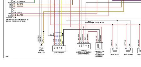
If spark does not exist, go to step 5). If spark does exist, inspect IGF circuit between distributor and ECM for short or open. See wiring diagram in the WIRING DIAGRAMS - 2.2L article.
Repair as needed. If circuit is okay, disconnect igniter connector. Igniter is behind air cleaner housing. Access ECM behind glove box. Turn ignition on. Using DVOM, backprobe ECM connector.
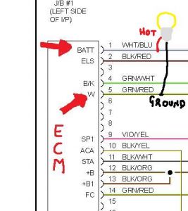
Measure voltage between terminal IGF and ground. See Fig. 5 (M/T Except Calif.) or 6 (A/T & M/T Calif.). If voltage is 4.5-5.5 volts, replace igniter and retest. If voltage is NOT 4.5-5.5 volts, replace ECM and retest.
Access ECM behind glove box. Turn ignition on. Using DVOM, backprobe ECM connector. Measure voltage between terminal IGT of ECM connector and ground, while cranking engine. Voltage should be .5-1.0 volt.
If voltage is within specification, go to next step. If voltage is NOT within specification, go to step 11).
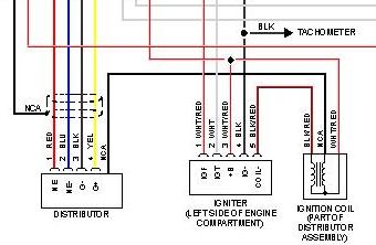
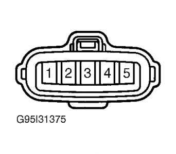
Disconnect igniter connector. Igniter is located behind air cleaner housing. Measure voltage between harness connector terminal No. 3 and ground. See Fig. 7 . Turn ignition switch to ON posit ion. Voltage should be 9-14 volts. Turn ignition switch to START position. Voltage should be 9-14 volts.
If voltage is NOT within specification, inspect igniter power supply circuit. See wiring diagram in WIRING DIAGRAMS - 2.2L article. Repair as needed.
If voltage is within specification, inspect circuit between ignition switch and ignition coil, ignition coil and igniter for open or short. See wiring diagram in WIRING DIAGRAMS - 2.2L article. Repair as needed. If circuit is okay, go to next step.
Inspect ignition coil. See the BASIC TESTING - 2.2L article. Replace ignition coil as needed. If ignition coil is okay, replace igniter and retest.
Access ECM behind glove box. Turn ignition on. Using DVOM, backprobe ECM connector. Ensure igniter connector is disconnected. Measure voltage between terminal IGT of ECM connector and ground, while cranking engine. See Fig. 5 (M/T Except Calif.) or Fig. 6 (A/T & M/T Calif.). Voltage should be .5-1.0 volt.
If voltage is within specification, replace igniter and retest. If voltage is NOT within specification, inspect IGT circuit between igniter and ECM for open or short. Repair as needed. If circuit is okay, replace ECM and retest.
Fig. 6: Identifying ECM Connector Terminals (A/T & M/T Calif.)


https://www.2carpros.com/forum/automotive_pictures/266999_6_6.jpg


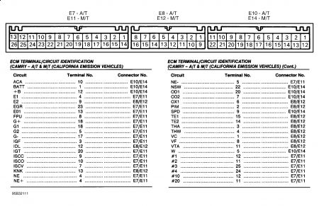
Fig. 7: Identifying Igniter Harness Connector Terminals


https://www.2carpros.com/forum/automotive_pictures/266999_7_6.jpg

Was this
answer
helpful?
Yes
No
Sunday, April 26th, 2009 AT 6:01 AM
Tiny
DAVE H
  • MECHANIC
  • 13,383 POSTS
I'm putting this diagram in for you to see the wire colors !!


https://www.2carpros.com/forum/automotive_pictures/266999_cam2_8.jpg

Was this
answer
helpful?
Yes
No
+1
Sunday, April 26th, 2009 AT 6:08 AM
Tiny
MBENCO
  • MEMBER
  • 184 POSTS
WOW Dave : That last reply was terrific. I think it's got everything I need to find the problem. Thanks, I'll get back to you after I do all the checks.
Was this
answer
helpful?
Yes
No
Sunday, April 26th, 2009 AT 8:47 AM
Tiny
MBENCO
  • MEMBER
  • 184 POSTS
Dave: Are the connectors in Fig.6 for my camry? The reason I ask is because in parenthesis above the picture it says for calif. Emission vehicles. If the connecters are for my car then it looks like the ECM isn't sending out any signals to the igniter because when I disconnect the igniter then turn the key on, I don't get any reading from the IGF wire (white/red) coming out of the ECM at terminal #3 on the E-7 connecter. Also I don't get any voltage from IGT wire while cranking the engine. I am getting 12 volts to the igniter connecter terminal #3 with ignition on and connecter disconnected.
Was this
answer
helpful?
Yes
No
Sunday, April 26th, 2009 AT 11:28 AM

Please login or register to post a reply.

Sponsored links