TIPM Connections PIN Out needed?

Tiny
GAVETGP84
  • MEMBER
  • 2006 DODGE RAM
  • 5.9L
  • 6 CYL
  • TURBO
  • 4WD
  • AUTOMATIC
  • 245,000 MILES
Looking for the diagram that shows the wiring diagram for the plug-in connectors on the back of the TIPM. Had a few connection issues and replaced the plugs and some of the pin connections and I think I may have 1 or 2 in the wrong spot. (I removed each wire and put them directly into the new plug one by one after cleaning or replacing the pin). But I may have put 1 or two of them in the wrong slot on the plugs as I am having new issues.
Tuesday, December 27th, 2022 AT 1:05 PM

13 Replies

Tiny
JACOBANDNICKOLAS
  • MECHANIC
  • 108,200 POSTS
Hi,

These things can be interesting to work on. I've seen so many fail.

Regardless, I attached the power distribution schematics first, then the TIPM schematic and last are the pin connectors.

Take a look through the pics and let me know if that helps or if you have other questions,

Take care,

Joe

See pics below. Note: The wiring schematic pages were cut in half and overlapped to make them readable.
Was this
answer
helpful?
Yes
No
Tuesday, December 27th, 2022 AT 7:56 PM
Tiny
GAVETGP84
  • MEMBER
  • 8 POSTS
Thanks for this. I will let you know if I have any further issues. Several of the pin connectors were badly corroded and so I cleaned a few and then opted to splice the really bad ones. I'm 90% positive that I put all the pin connectors in the right slots in each plug but now my truck is saying "no bus" and my gauges will freeze and then drop to zero. I'm hoping that my ECM didn't go bad during the week it's been sitting due to this. My TIPM was replaced in May due to corrosion on the terminals, but they didn't do anything for the connectors at that time. Recently I've been having a slew of issues from my dome lights coming on and not shutting off to my 4wd locking itself in 4wd but saying it in "N" with all my 4wd lights on, lol. So, it's not been a fun week.
Was this
answer
helpful?
Yes
No
-1
Wednesday, December 28th, 2022 AT 4:47 AM
Tiny
JACOBANDNICKOLAS
  • MECHANIC
  • 108,200 POSTS
The no bus is indicating a lack of communication. Based on your description, it sounds like the problem is between the TIPM and the cluster.

Let me know what you find or if I can help.

Take care,

Joe
Was this
answer
helpful?
Yes
No
Wednesday, December 28th, 2022 AT 11:51 AM
Tiny
GAVETGP84
  • MEMBER
  • 8 POSTS
It did not fix my issue. All fuses checked out. I rechecked all my wires.
Was this
answer
helpful?
Yes
No
Thursday, December 29th, 2022 AT 3:40 PM
Tiny
GAVETGP84
  • MEMBER
  • 8 POSTS
This is what is currently doing.
Was this
answer
helpful?
Yes
No
Thursday, December 29th, 2022 AT 4:28 PM
Tiny
JACOBANDNICKOLAS
  • MECHANIC
  • 108,200 POSTS
Hi,

That would certainly be enough to drive me crazy. LOL Did this just start after it sat? I do have another question. Please understand that I am watching a video, so I could be completely wrong.

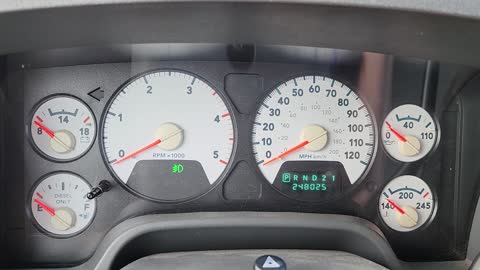
I didn't like the alternator output. Before starting, it was at 12v. When it started, it hardly went up at all. I don't know if you had the electrical system loaded, but it should have been approximately 14v running.

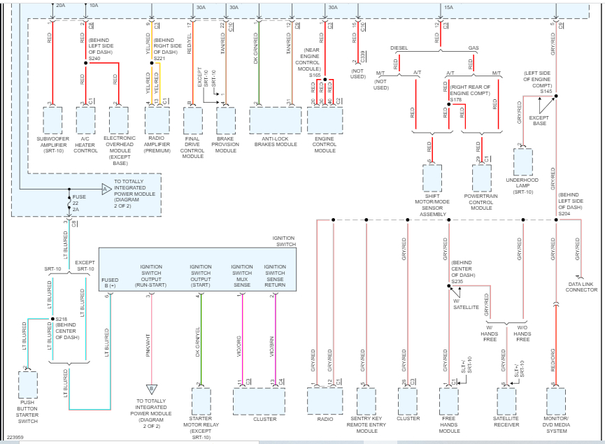
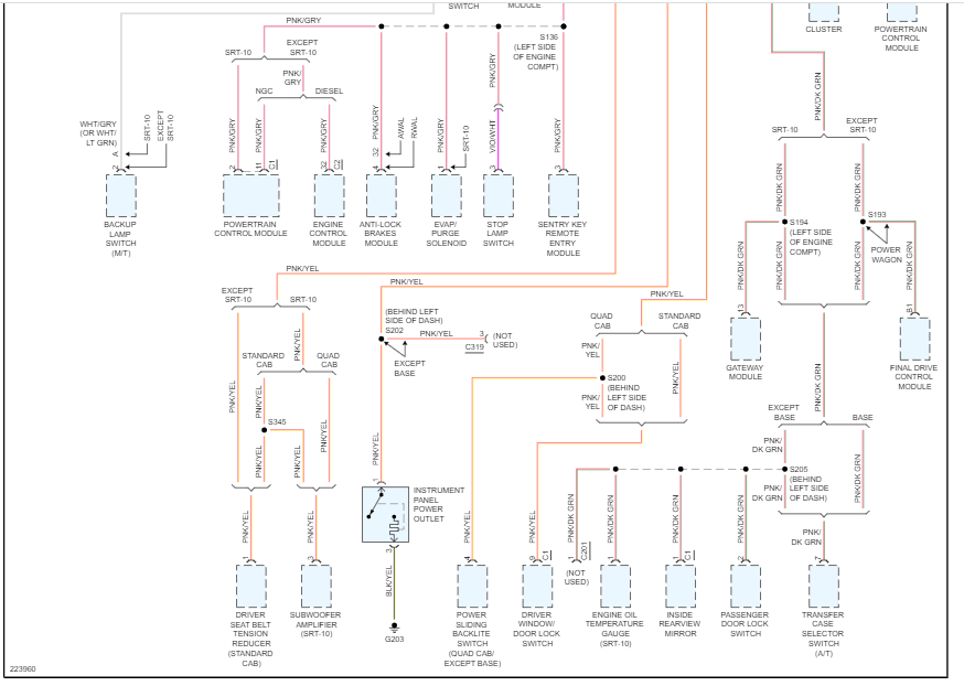
I'm suggesting this because the tachometer is controlled by the instrument cluster circuit board based upon cluster programming and electronic messages received by the cluster from the Engine Control Module (ECM) on vehicles equipped with a diesel engine over the Controller Area Network (CAN) data bus. I ask because the electronics on these vehicles are very sensitive to low voltage. It's just a thought.

Also, since this is likely a CAN-related issue or the cluster itself is failing, you should consider having the can-bus scanned for codes.

Here is a link that explains how that is done:

https://www.2carpros.com/articles/can-scan-controller-area-network-easy

If you haven't, you may want to just check if the alternator is putting out near 14v when the engine is running.

Here is a link that shows how it's done:

https://www.2carpros.com/articles/how-to-check-a-car-alternator

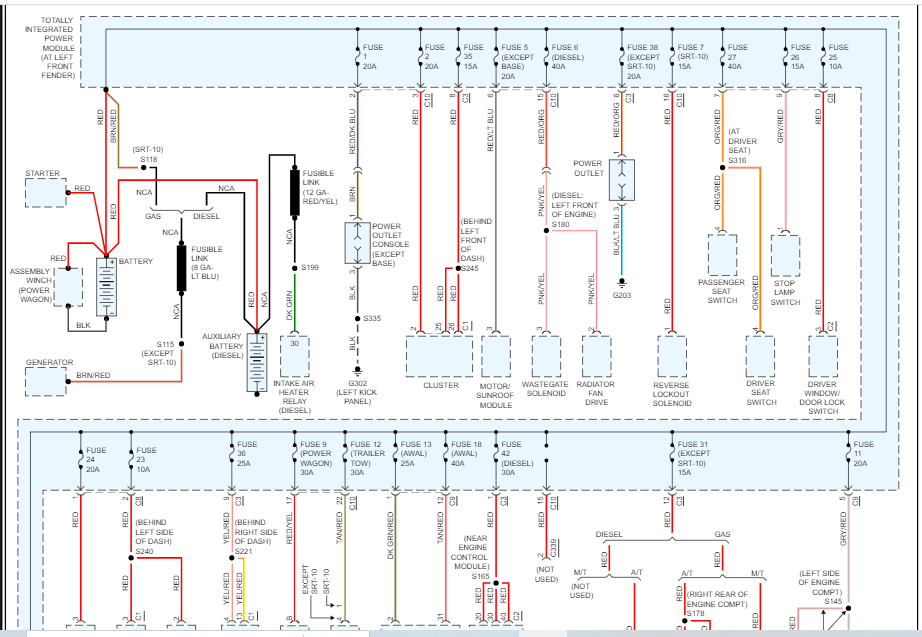
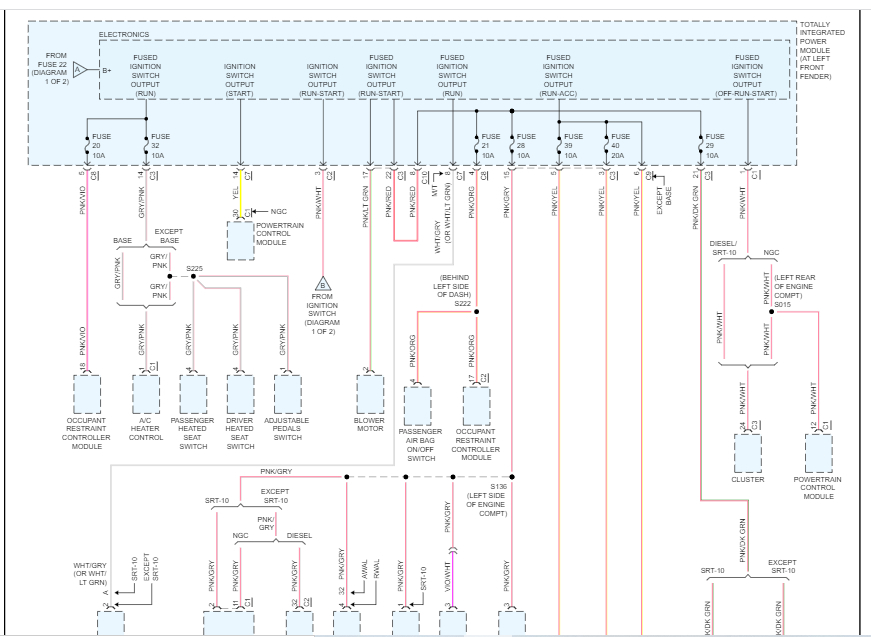
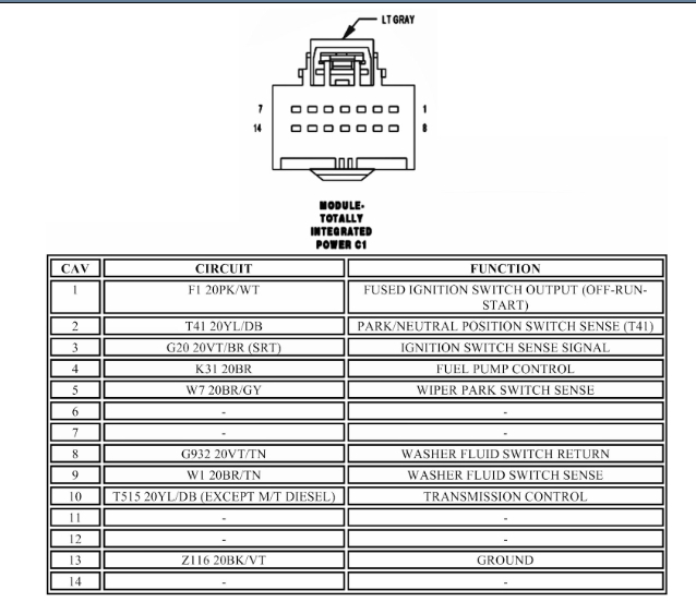
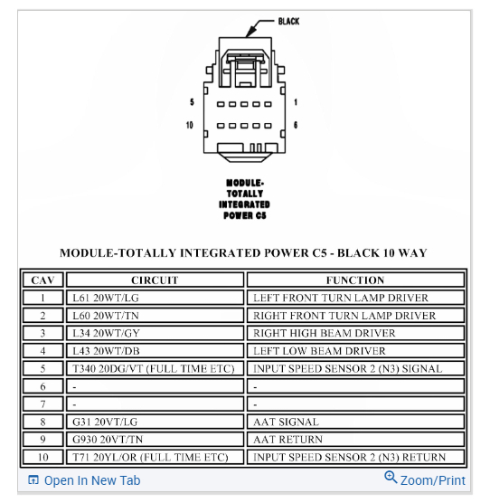
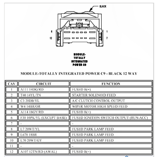
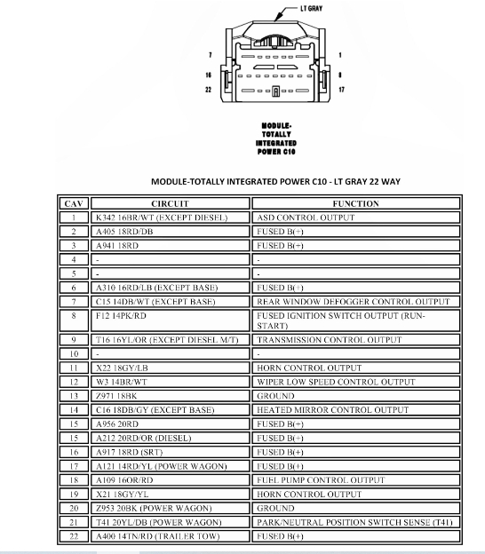
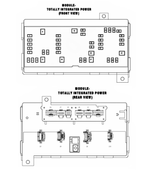
I have a few other things to check. Check the ABS module fuse (10 amp fuse, #28 in the TIPM). Make sure the fuse is tight and there isn't a corrosion issue. Also, check the connectors at the module to make sure there isn't an issue. If you have a live data scan tool, check to see if you can communicate with the ABS module when the tachometer drops.

Let me know.

Joe
Was this
answer
helpful?
Yes
No
Thursday, December 29th, 2022 AT 9:25 PM
Tiny
GAVETGP84
  • MEMBER
  • 8 POSTS
Right before this video I just got done unhooking all the TIPM connections and cleaning the connectors and the pins with electrical connector spray. When I replaced the plug connectors (new plugs same wires mostly) there were a few badly corroded pin connectors a few I just cleaned really well with battery terminal corrosion cleaner and the rest I actually removed and spliced together. Two of those were the "can bus" wires so I'm wondering if the connection in the splice is weak and not allowing the correct amount of voltage to pass through.

All I have as far as a scanner is an Innovo scan tool. It doesn't do much at all. I did notice the voltage gauge issue as well. But choked it up to the same issue that's causing the no bus signal as well as the abs/brake light issue. I'm thinking I should replace more of the can bus wires further down the wire instead of right behind the plug to allow me to get a better solder on the connection.
Was this
answer
helpful?
Yes
No
Friday, December 30th, 2022 AT 3:36 AM
Tiny
JACOBANDNICKOLAS
  • MECHANIC
  • 108,200 POSTS
Hi,

What you're saying sounds very possible. I don't see why the cluster would have failed if it was working properly before.

As far as the splices are concerned, make sure they are in good condition. I don't know how you did things, but if you are splicing wires, they should be soldered, and heat shrunk. At least that is how I would do it.

Let me know what you find. I'm interested in knowing.

Take care,

Joe
Was this
answer
helpful?
Yes
No
Friday, December 30th, 2022 AT 10:12 PM
Tiny
GAVETGP84
  • MEMBER
  • 8 POSTS
Well, I redid the wire connections, and it did not fix my issue at all. Still has the same issues. I'm assuming at this point my ECM is shot, or the TIPM or both.
Was this
answer
helpful?
Yes
No
Tuesday, January 3rd, 2023 AT 4:43 PM
Tiny
GAVETGP84
  • MEMBER
  • 8 POSTS
I checked the voltage, and it was about 14.7 v while running. Checked the batteries and the alternator. And double checked my fuses.
Was this
answer
helpful?
Yes
No
Tuesday, January 3rd, 2023 AT 4:44 PM
Tiny
JACOBANDNICKOLAS
  • MECHANIC
  • 108,200 POSTS
Have you checked the specific pins at the TIPM to see if they are performing as they should? If they are, then it is likely something different. If they aren't, then the TIPM is the likely issue.

Let me know.

Joe
Was this
answer
helpful?
Yes
No
Tuesday, January 3rd, 2023 AT 8:41 PM
Tiny
GAVETGP84
  • MEMBER
  • 8 POSTS
I don't know how to do that. I'll see if I can find some videos on YouTube explaining how to do that.

I'll get back to you today.
Was this
answer
helpful?
Yes
No
Wednesday, January 4th, 2023 AT 3:56 AM
Tiny
JACOBANDNICKOLAS
  • MECHANIC
  • 108,200 POSTS
Hi,

No problem. With the connector off the TIPM, simply locate the pins in question and check at that point.

Let me know.

Joe
Was this
answer
helpful?
Yes
No
Wednesday, January 4th, 2023 AT 7:20 PM

Please login or register to post a reply.

Sponsored links