I have a feeling that is what happened.
______________________
I don't know if you need them, but here are the directions for removal and replacement of the intake. Torque specs tightening sequence and other info is included. See pics attached.
_____________________
2006 Kia Truck Sorento 4WD V6-3.5L
Procedures
Vehicle Engine, Cooling and Exhaust Engine Intake Manifold Service and Repair Procedures
PROCEDURES
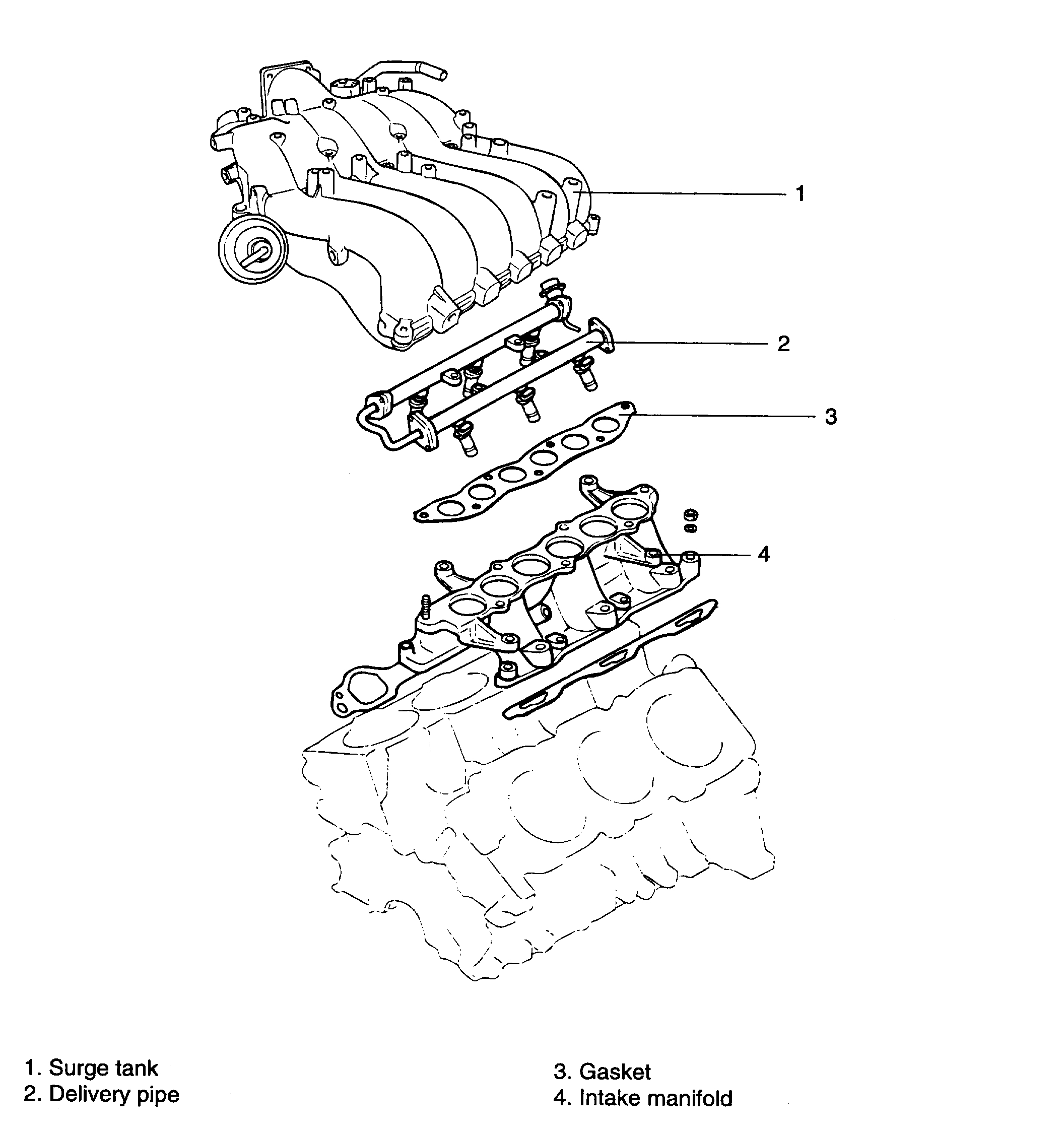
INTAKE MANIFOLD
pic 1
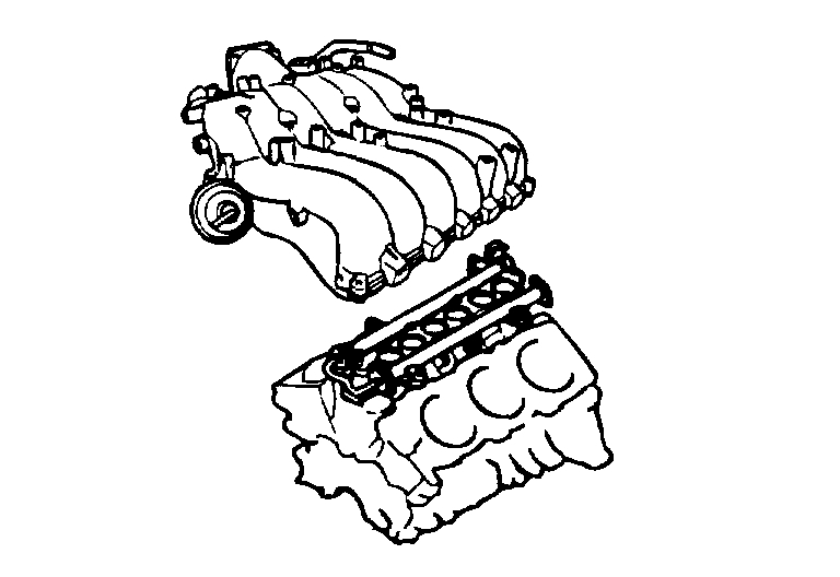
COMPONENTS
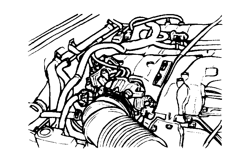
REMOVAL
pic 2
1. Remove the air intake hose connected to the throttle body.
2. Remove the accelerator and cruise control cables.
3. Remove the engine coolant hose and throttle body.
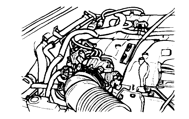
4. Remove the P.C.V. hose and brake booster vacuum hoses.
pic 3
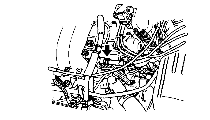
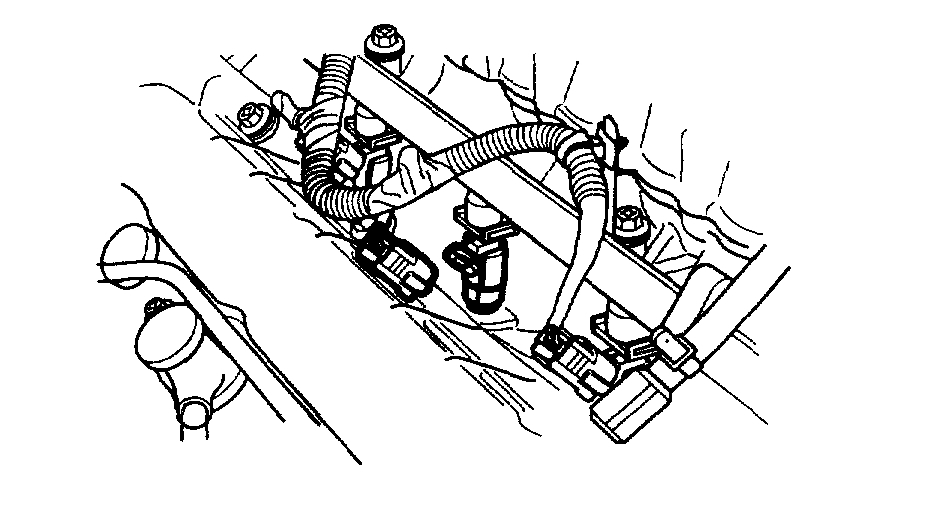
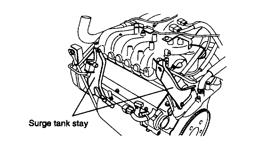
5. Disconnect the vacuum hose connections.
pic 4
pic 5
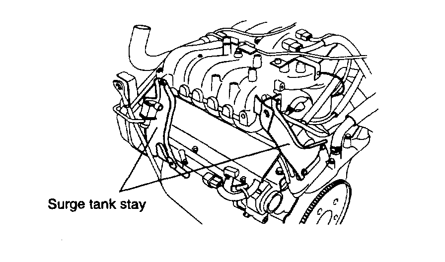
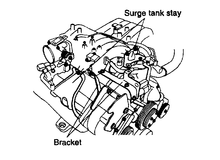
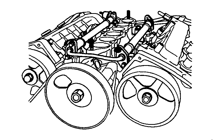
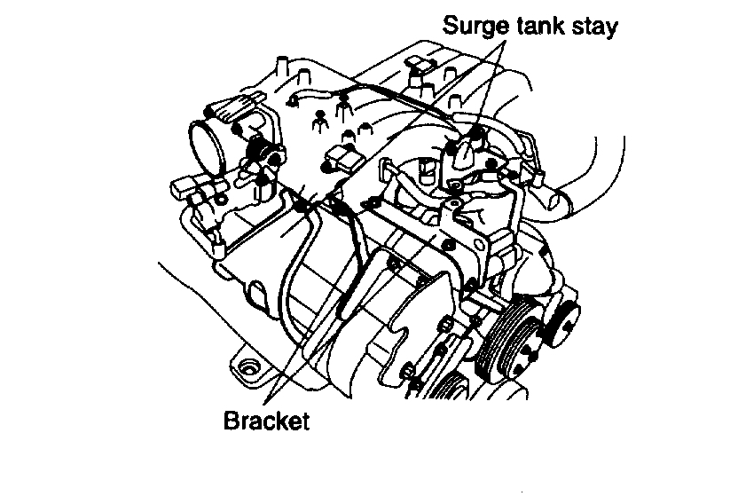
6. Remove the surge tank stay.
7. Bleed off the pressure in the fuel pipe line to prevent the fuel from spilling.
pic 6
8. Disconnect the connector from high pressure hose.
pic 7
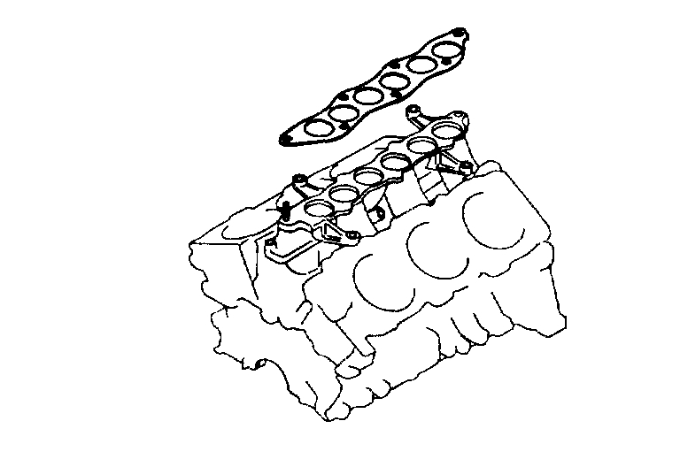
9. Remove the surge tank and gasket.
pic 8
10. Disconnect the fuel injector harness connector
pic 9
11. Remove the delivery pipe with the fuel injector and the pressure regulator.
NOTE: When the delivery pipe is removed, be careful not to drop an injector.
12. Disconnect the wiring harness of the coolant sensor assembly.
pic 10
13. Remove the surge tank.
INSPECTION
SURGE TANK AND INTAKE MANIFOLD
1. Check the surge tank and intake man if old for damage, cracking or restriction of the vacuum outlet port, water or gas passages.
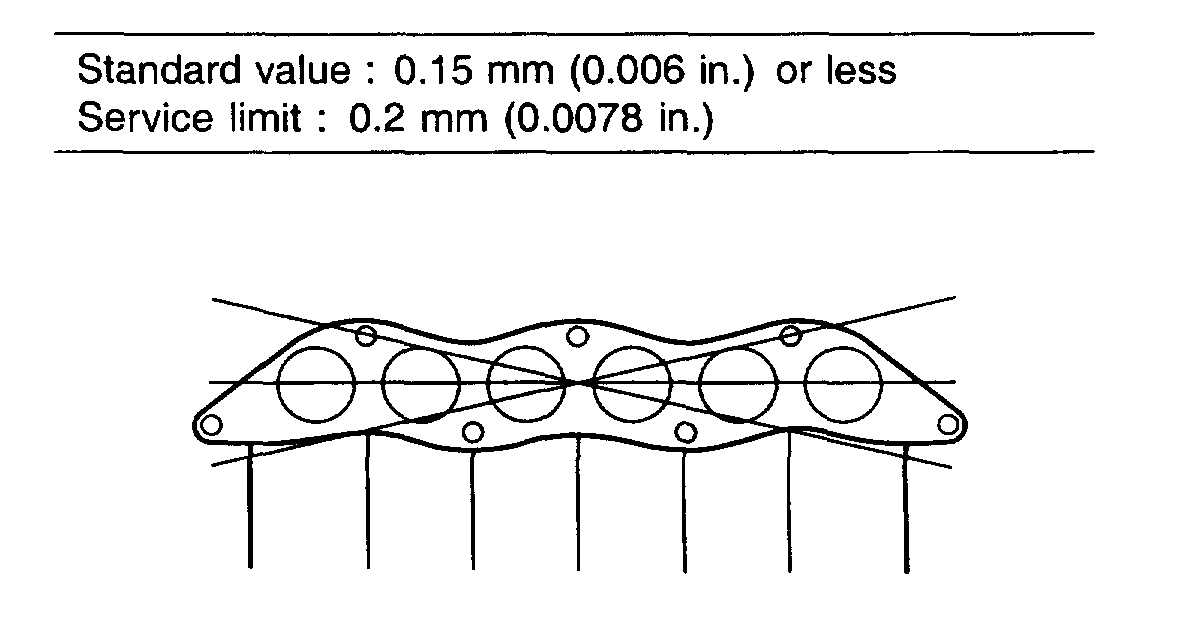
pic 11
2. Check for distortion on the surface using a straight edge and feeler gauge.
Standard value: 0.15 mm (0.006 inch) or less
Service limit: 0.2 mm (0.0078 inch)
INSTALLATION
pic 12
pic 13
pic 14
1. Install the intake manifold and delivery pipe reversing the order of the removal procedure.
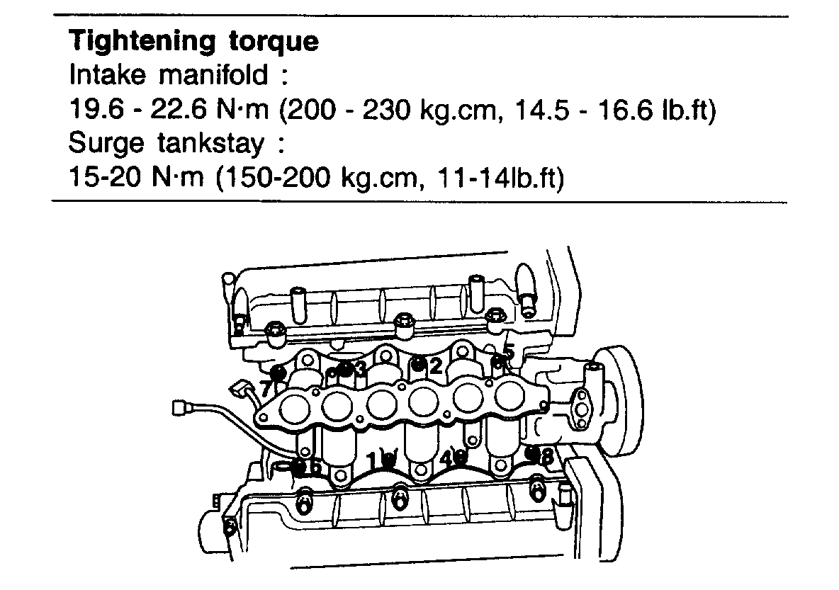
Tightening torque
Intake manifold: 19.6 - 22.6 Nm (200 - 230 kg-cm, 14.5 - 16.6 ft. lbs.)
Surge tankstay: 15 - 20 Nm (150 - 200 kg-cm, 11 - 14 ft. lbs.)
_______________________________________
Here are all the directions for cylinder head inspection and repair.
2006 Kia Truck Sorento 4WD V6-3.5L
Removal and Replacement
Vehicle Engine, Cooling and Exhaust Engine Cylinder Head Assembly Service and Repair Procedures Removal and Replacement
REMOVAL AND REPLACEMENT
CYLINDER HEAD
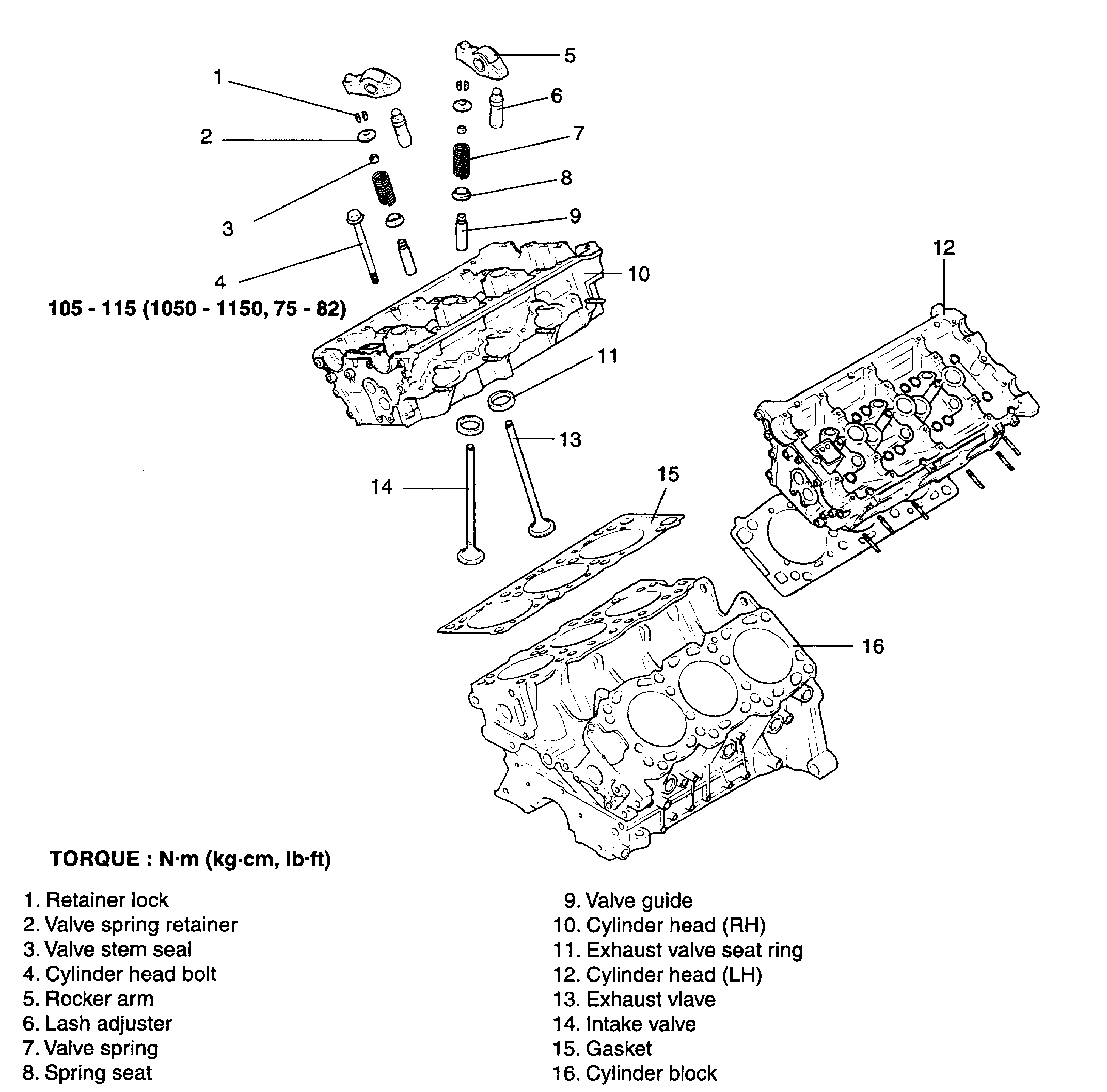
pic 15
COMPONENTS
DISASSEMBLY
1. Drain the coolant and disconnect the upper radiator hose.
2. Remove the breather hose and air-intake hose.
3. Remove the vacuum hose, fuel hose and coolant hose.
4. Remove the intake manifold.
5. Remove the cables from the spark plugs. The cables should be removed by holding the boot portion.
6. Remove the ignition coil.
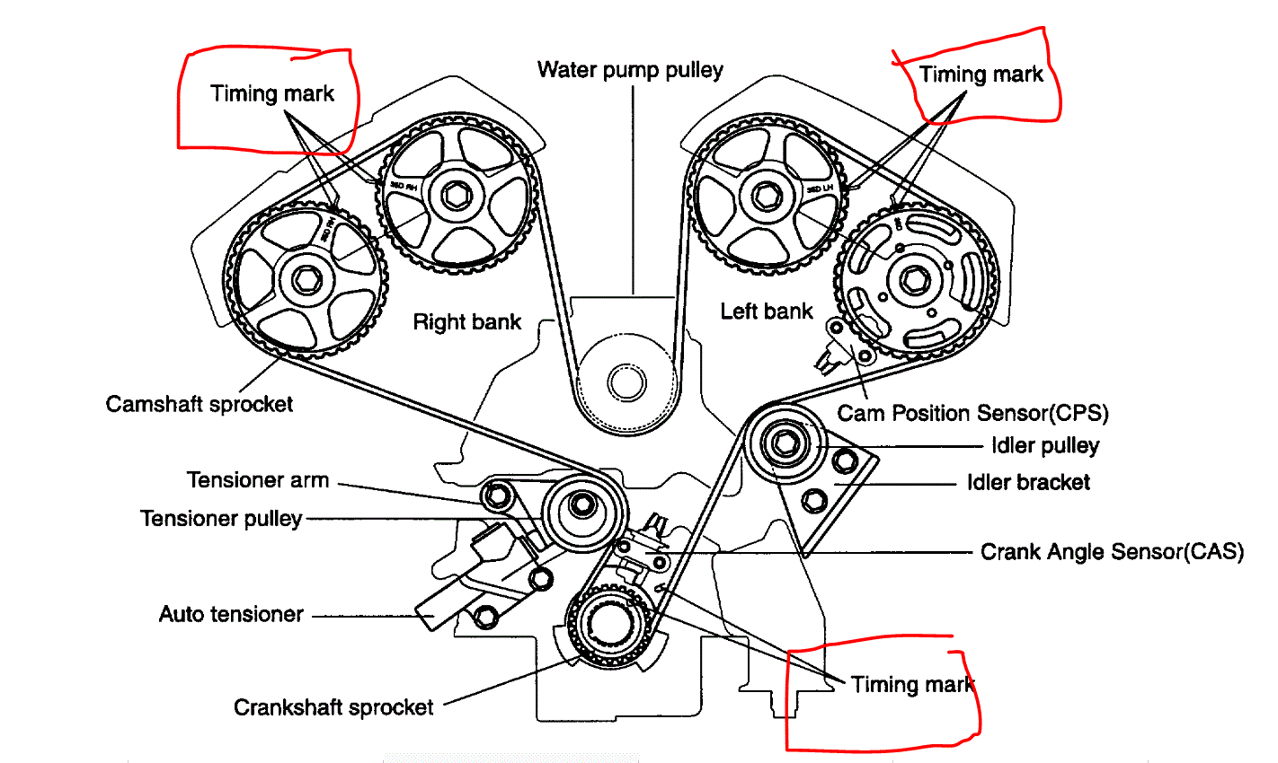
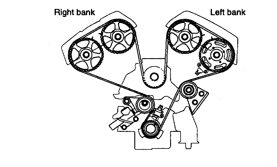
7. Remove the upper and lower timing belt cover.
pic 16
8. Remove the timing belt and camshaft sprockets.
9. Remove the heat protector and exhaust manifold assembly.
10. Remove the coolant pump pulley and head cover.
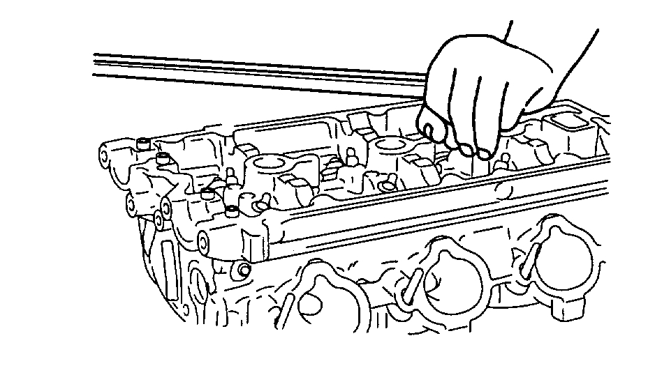
11. Remove the intake and exhaust camshaft.
pic 17
pic 18
12. Remove the cylinder head assembly. The cylinder head bolts should be removed using the 12 mm socket, in two or three steps.
13. Clean the gasket pieces from the cylinder block top surface and cylinder head bottom surface.
NOTE: Make sure that fragments from the gasket do not fall in the engine.
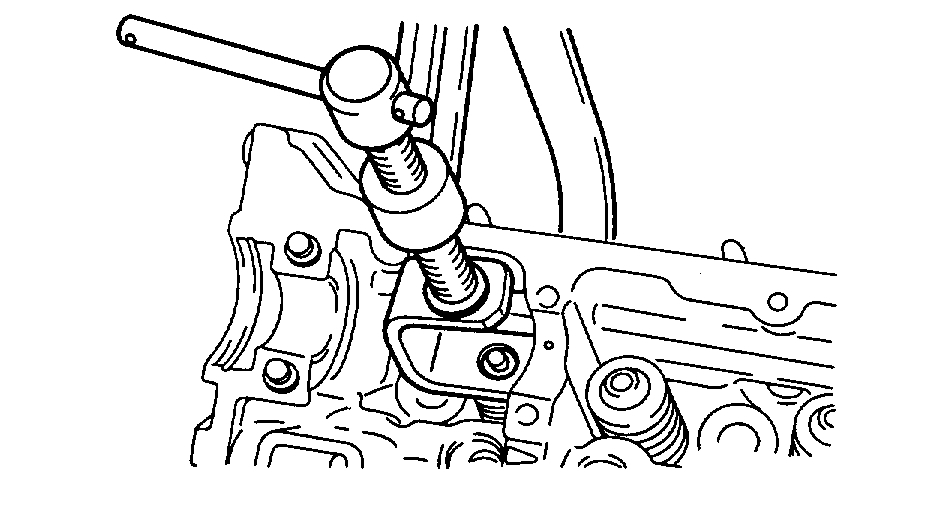
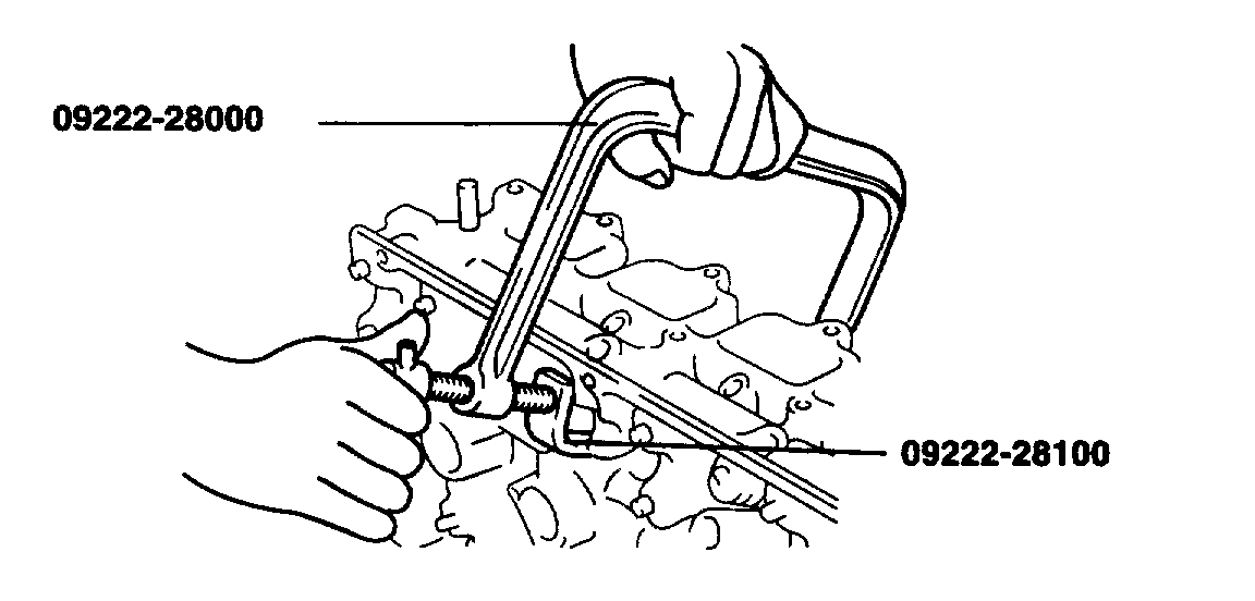
RETAINER LOCK
1. Compress the valve spring using special tool. (09222-28000, 09222-28100)
pic 19
2. Remove the retainer lock.
INSPECTION
CYLINDER HEAD
1. Remove scale, sealing compound and carbon deposits. After cleaning oil passages, apply compressed air to make certain that the passages are not clogged.
2. Visually check the cylinder head for cracks, damage or water leakage.
pic 20
3. Check the cylinder head surface for flatness with a straight edge and feeler gauge as shown in the illustration.
Cylinder head flatness:
Standard dimensions: Maximum 0.03 mm (0.0059 inch)
Service limit: 0.05 mm (0.0020 inch)
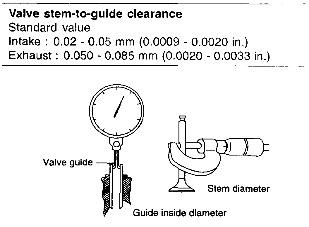
VALVE GUIDES
pic 21
Check the valve stem-to-guide clearance. If the clearance exceeds the service limit, replace the valve guide with a new oversize guide.
Valve stem-to-guide clearance
Standard value
Intake: 0.02 - 0.05 mm (0.0009 - 0.0020 inch)
Exhaust: 0.050 - 0.085 mm (0.0020 - 0.0033 inch)
VALVE
1. Replace the valve if its stem is bent, worn or damaged. Also replace it if the stem end (the surface contacting the hydraulic-lash adjuster) is hollowed out.
pic 22
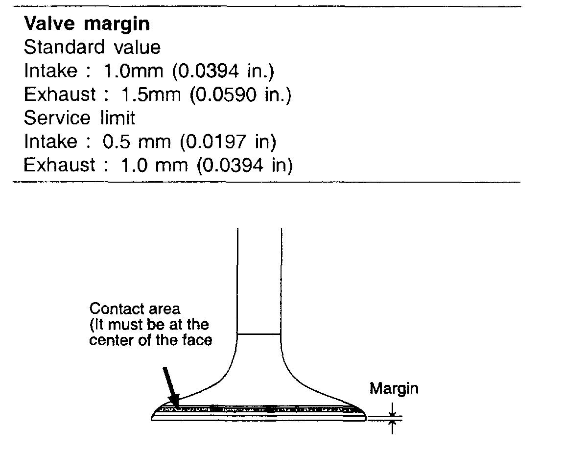
2. Check the valve face contact area, and recondition or replace as necessary.
pic 23
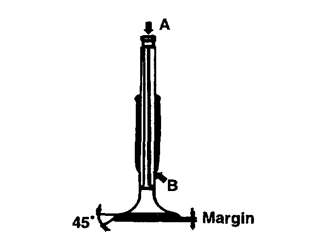
3. Replace the valve if the width of the margin (thickness of the valve head) is less than the minimum specified.
Valve margin
Standard value
Intake: 1.0 mm (0.0394 inch)
Exhaust: 1.5 mm (0.0590 inch)
Service limit
Intake: 0.5 mm (0.0197 inch)
Exhaust: 1.0 mm (0.0394 inch)
VALVE SPRING
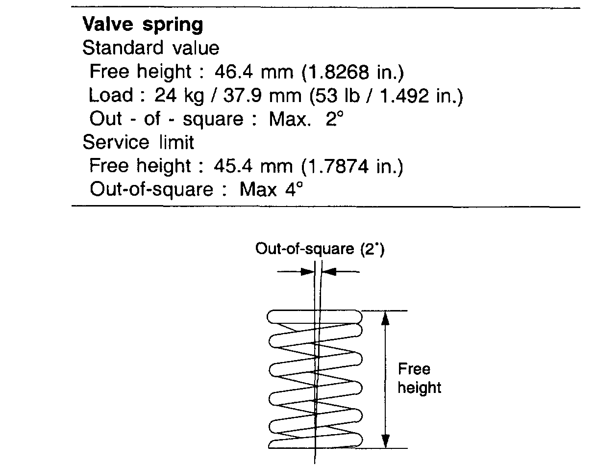
1. Check the free height of each valve spring and replace if necessary.
pic 24
2. Using a square, test the squareness of each valve spring. If the spring is excessively out-of-square, replace it.
Valve spring
Standard value
Free height: 46.4 mm (1.8268 inch)
Load: 24 kg /37.9 mm (53 lb / 1.492 inch)
Out-of-square: Maximum 2°
Service limit
Free height: 45.4 mm (1.7874 inch)
Out-of-square: Maximum 4°
RECONDITIONING VALVE SEAT
1. Before reconditioning, check the valve guide for wear. Replace worn guides if necessary and then recondition the valve seats.
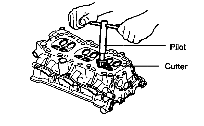
2. Recondition the valve seat using the Valve Seat Cutter and Pilot.
pic 25
3. After reconditioning, the valve and valve seat should be lapped lightly with a lapping compound.
REPLACING VALVE GUIDE
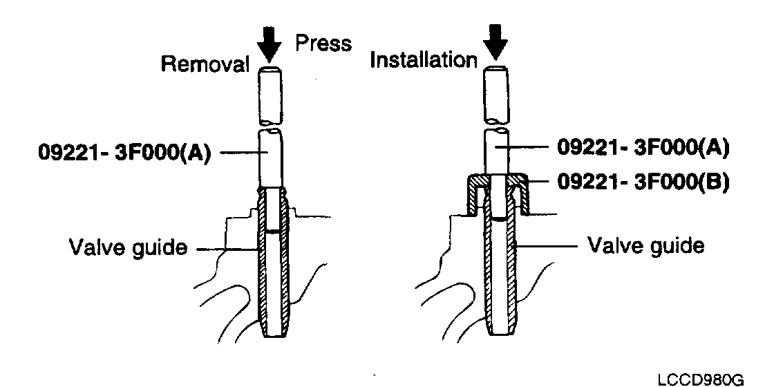
1. Using the special tool (09221-3F000(A)), withdraw the old valve guide out the bottom of the cylinder head.
pic 26
2. Recondition the valve guide hole so that it can receive the newly press-fitted oversize valve guide.
pic 27
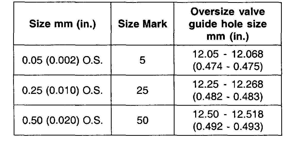
VALVE GUIDE OVERSIZES
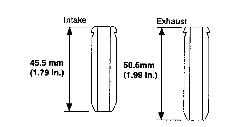
3. Using the special tool (09221-3F000 (A), 09221-3F000(B)) press-fit the valve guide. The valve guide must be press-fitted from the upper side of the cylinder head. Keep in mind that the intake and exhaust valve guides are different in length.
4. After the valve guide is press-fitted, insert a new valve and check for proper clearance.
pic 28
5. After the valve guide is replaced, check that the valve is fully seated. Recondition the valve seats as necessary.
NOTE: Do not install a valve guide unless it is oversize.
REPLACING VALVE SEAT RING
pic 29
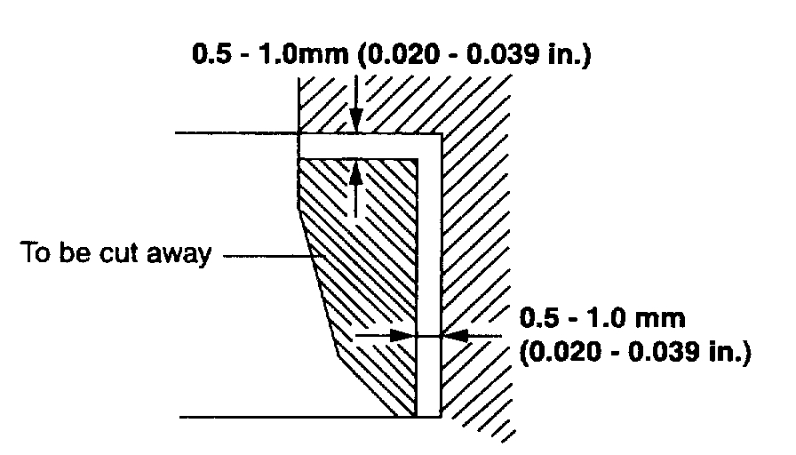
1. Cut away the inner face of the valve seat to reduce the wall thickness.
pic 30
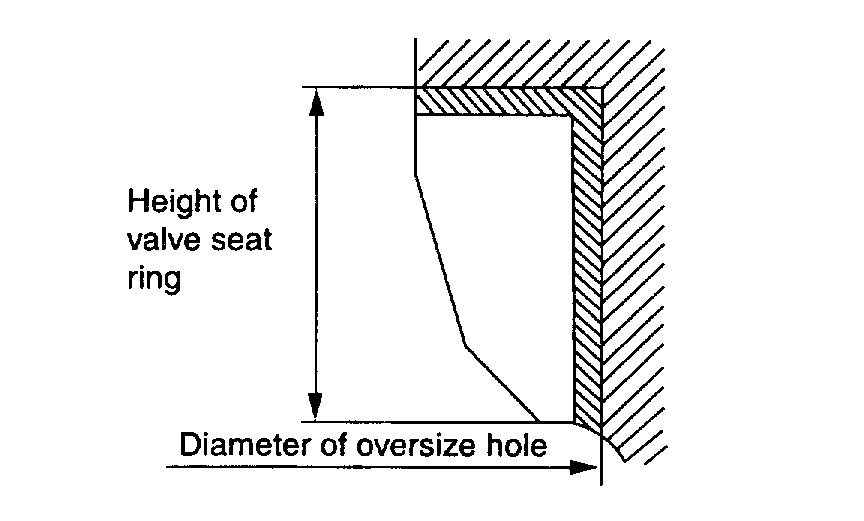
2. Enlarge the diameter of the valve seat so that it matches the specified hole diameter of the new valve seat ring.
pic 31
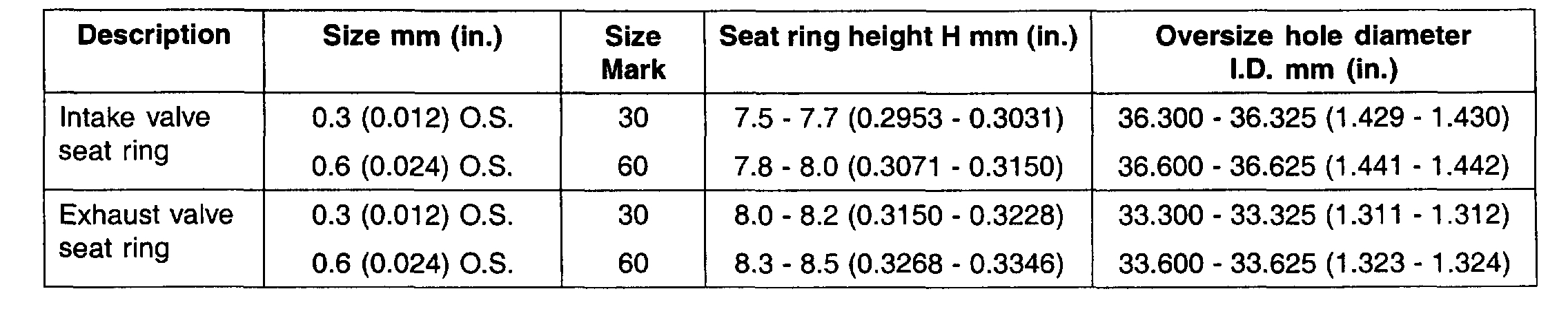
VALVE SEAT RING OVERSIZES
3. Heat the cylinder head to about 250°C (480°F) and press-fit an oversize seat ring for the bore in the cylinder head.
4. Using lapping compound, lap the valve to the new seat.
Valve seat contact width
Intake: 0.9 - 1.3 mm (0.035 - 0.051 inch)
Exhaust: 0.9 - 1.3 mm (0.035 - 0.051 inch)
REASSEMBLY
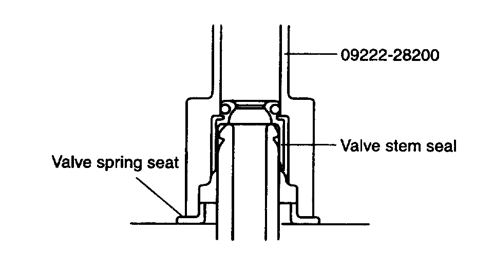
1. Install the spring seats.
pic 32
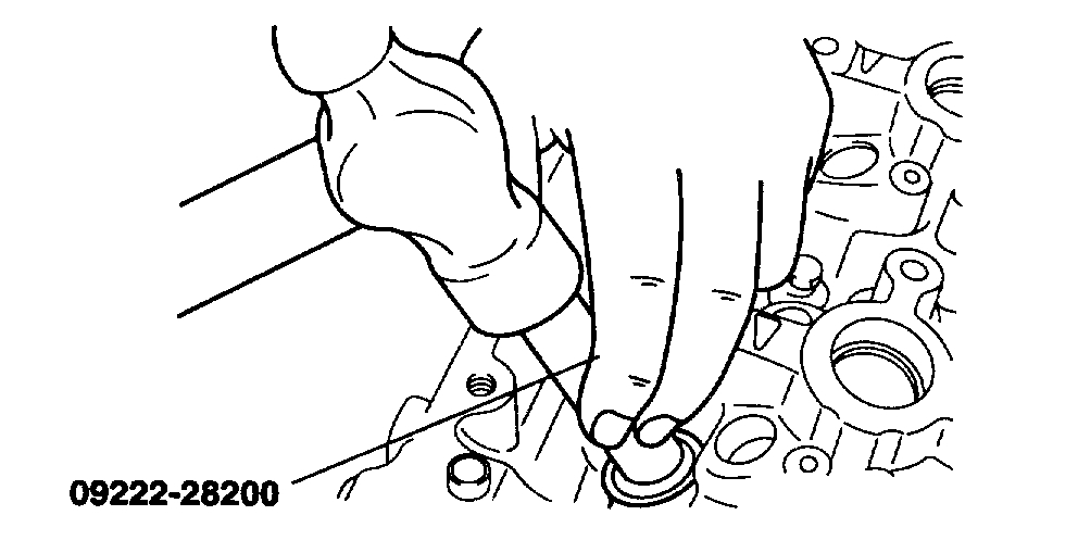
pic 33
2. Using special tool (09222-28200), lightly tap the seal in position.
NOTE:
- Do not reuse old valve stem seals.
- Incorrect installation of the seal could result in oil leakage of from the valve guides.
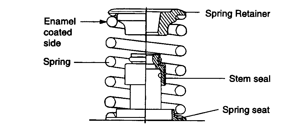
3. Apply engine oil to each valve. Insert the valve into their guides. Avoid pushing the valve into the seal by force. After installing the valve, check that it moves smoothly.
pic 34
4. Place valve springs so that the side coated with enamel faces toward the valve spring retainer.
pic 35
5. Using the special tool (09222-28000, 09222-28100), compress the spring and install the retainer locks. After installing the valves, ensure that the retainer locks are correctly in place before releasing the valve spring compressor.
NOTE: When the spring is compressed, check that the valve stem seal is not pressed against the bottom of the retainer.
6. Clean both gasket surfaces of the cylinder head and cylinder block.
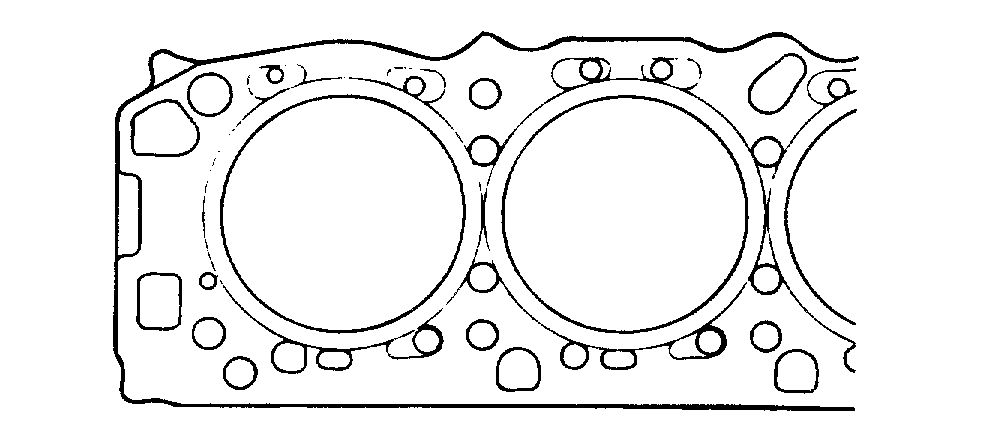
7. Verify the identification marks on the cylinder head gasket.
pic 36
8. Install the gasket so that the surface with the identification mark faces toward the cylinder head.
NOTE: Do not apply sealant to these surfaces.
pic 37
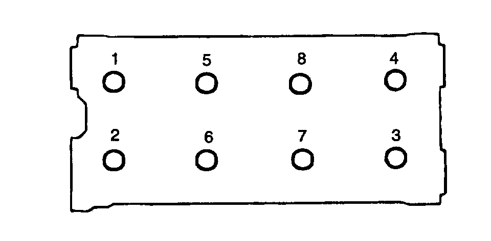
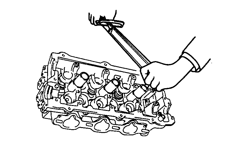
9. Tighten the cylinder head bolts in the sequence shown in the illustration with a torque wrench.
pic 38
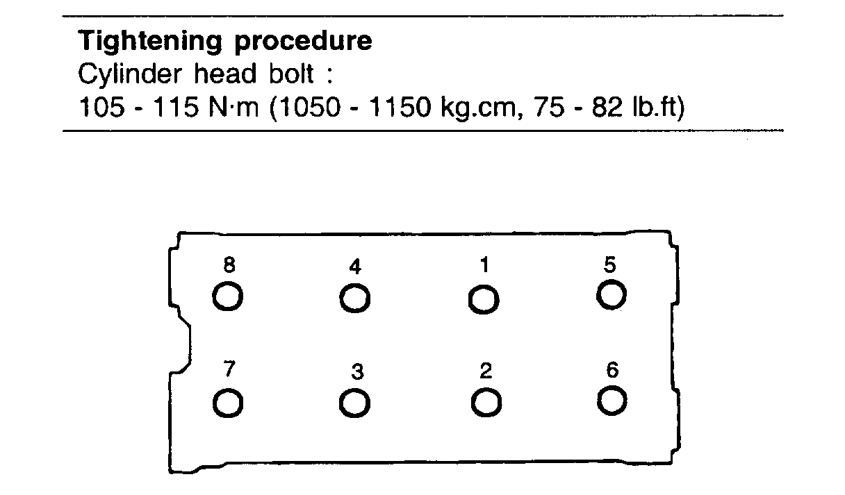
10. Tighten the cylinder head bolts using the torque-angle method. Starting at top center, tighten all cylinder head bolts in sequence as shown in the illustration, using the 12 mm socket.
Tightening procedure
Cylinder head bolt: 105 - 115 Nm (1050 - 1150 kg-cm, 75 - 82 ft. lbs.)
________________________________
Let me know if this helps or if you have other questions.
Take care,
Joe
Images (Click to enlarge)
Mar 2, 2020 at 8:01 PM